Article

Nonlinear Controllers Based on Exact Feedback Linearization for Series-Compensated DFIG-Based Wind Parks to Mitigate Sub-Synchronous Control Interaction

School of Electronic Information and Electrical Engineering, Shanghai Jiao Tong University, Shanghai 200240, China
*
Author to whom correspondence should be addressed.
Energies 2017, 10(8), 1182; https://doi.org/10.3390/en10081182
Submission received: 10 July 2017 / Revised: 3 August 2017 / Accepted: 7 August 2017 / Published: 10 August 2017
(This article belongs to the Section F: Electrical Engineering)

Abstract

:
The increasing penetration of wind power in the grid has driven the integration of wind farms with power systems that are series-compensated to enhance power transfer capability and dynamic stability. This may lead to sub-synchronous control interaction (SSCI) problems in series-compensated doubly-fed induction generator (DFIG)-based wind farms. To mitigate SSCI, nonlinear controllers based on exact feedback linearization (EFL) are proposed in this paper. Before deriving the control laws, the exact feedback linearizability of the studied system is scrutinized. Frequency scanning analysis is employed to test the designed EFL controllers. Moreover, the performance of the EFL controllers is compared to that of classical proportional-integral (PI) controllers. A series-compensated 100 MW DFIG-based wind park is utilized to assess the performance of the designed controllers through the alleviation of sub-synchronous resonance. Analyses of the studied system reveal that the resistance is negative under sub-synchronous frequency conditions, whereas the reactance becomes negative at approximately 44 Hz. The designed EFL controllers effectively alleviate SSCI and result in positive reactance and resistance values within the whole sub-synchronous frequency range. The results from the frequency scanning method are also validated through the time domain simulation and the eigenvalue analysis.

1. Introduction

In recent years, wind energy has been the fastest-developing type of renewable resource compared to other green resources. Variable speed generator wind turbines are predominating in China, North America, and Europe, among other wind parks [1]. Over the last few decades, the doubly-fed induction generator, an important type of variable speed generator wind turbines, has drawn much attention owing to its independent power control and low converter rating [2,3]. The integration of huge-scale DFIG-based wind parks requires the considerable upgrading of distribution and transmission infrastructures. Capacitive series compensation, a classical type of such upgradation, is an economical method for increasing dynamic stability and power transfer capability in transmission lines [4,5]. However, when DFIG-based wind parks are connected to the grid through capacitive series compensation, there can be a risk of sub-synchronous resonance (SSR), even though the compensation level is not too high. SSR is a condition in which the wind park exchanges energy with the electric network at one or more natural frequencies of the mechanical or electrical part of the system [6]. The frequency of the exchanged energy is below the fundamental frequency of the combined system, which may lead to shaft failure. Two traditional types of SSR effect in DFIG-based wind farms have been identified: torsional interactions and the induction generator effect [7,8]. In the case of torsional interactions, the complement to the torsional natural frequency of the DFIG drive-train shaft system can be extremely near to the natural frequency of the grid. Consequently, the sub-synchronous torque components due to the sub-synchronous induced armature voltage can be sustained [7]. As for the induction generator effect, the effective rotor resistance can be negative under sub-synchronous frequencies; then sub-synchronous currents will be sustained [8].
With the rapid development of DFIG technology for wind parks, a new form of SSR is recognized, known as sub-synchronous control interaction (SSCI). SSCI was first identified in the incident that occurred at wind parks situated in Texas, USA in 2009, which resulted in the drop-out of a number of wind turbine generators [9]. Unlike the aforementioned classical SSR, SSCI is an electrical interaction between power electronic converters of DFIG and series-compensated transmission lines, with no mechanical system involved. As a result, SSCI develops faster compared to torsional interactions and the induction generator effect due to less damping [10]. Moreover, the frequency of traditional SSR depends on the fixed torsional mode, whereas the frequency of SSCI is not fixed, for the un-damped oscillations depend on the configuration of the converters of DFIG and the electrical transmission system [11].
There is a considerable amount of literature on the design of countermeasures to alleviate SSCI (or SSR) and to enhance system stability, which can be divided into three categories: (1) enhancement of wind turbine generator control strategy; (2) inclusion of flexible AC transmission systems (FACTS) devices; and (3) the design and use of relay protection [12]. As the third line of defense to SSCI, relay protection is regarded as a last resort. The relay, which can detect sub-synchronous frequency, is applied to prevent the occurrence of sub-synchronous problems [12]. Microprocessor based relays implementing a novel algorithm are utilized in two wind farms as backup protection and field tests demonstrate their effectiveness [9]. As the second line of defense to SSCI, properly designed FACTS devices can be used in electric systems with DFIGs to take full advantage of the series compensation [13]. In addition, the flexibility of changing the compensation level and the ability to effectively damp electromechanical oscillations and sub-synchronous resonance make them a versatile and attractive series compensation option [14]. Damping is accomplished utilizing a Static Var System ancillary controller combined with a continuous controlled series compensator [15]. The thyristor controlled series capacitor appears as a resistor at a sub-synchronous frequency and reduces the resonance [16]. A control scheme of the gate-controlled series capacitor is proposed for alleviating SSR in DFIG-based wind parks [17]. A static synchronous series compensator (SSSC) is utilized in a series-compensated wind park for SSR mitigation [18]. A novel SSSC is designed with an estimation algorithm that can extract the sub-synchronous components of the line current using Kalman filters [19]. However, the inclusion of FACTS or relay protection is not an economical way to alleviate SSCI.
As the first line of defense to SSCI, the enhancement of the existing controller for DFIG converters is a feasible economical solution to a SSCI problem. A supplementary damping control strategy is presented in [20,21] when similar controllers are included as an auxiliary setup for the converters in DFIG-based wind parks in [22]. A novel two-degree-of-freedom controller in combination with damping control loops is proposed in [23]. Auxiliary damping controllers are integrated with the master controllers for DFIG converters to accomplish superior performance in [24]. In [25], an auxiliary damping controller uses auxiliary loads to realize the damping objective by adding a supplementary speed signal to the motor speed reference in the variable-frequency-drive’s closed loop control. A proportional damping control strategy is proposed in [5], where the input control signals are optimally selected to be placed at the optimal point within the rotor side converter (RSC). Two notch filters are inserted into the q-axis and d-axis channels in the current control loop of the RSC controller to mitigate SSCI [26]. In the aforementioned linear controllers, there are a series of tuning variables, which can be extremely challenging to tune due to changing atmospheric conditions, and the improvement of the control scheme of the grid side converter (GSC) is often disregarded in the literature [20,21,22,23,24,25]. In addition, in the design process of the controllers for alleviating SSCI, the details of the dynamics of the studied system should be retained as much as possible, especially the nonlinear dynamics associated with the control of DFIG converters [27]. However, classical linear methods are employed in the majority of the literature [4,20,21,22,23,24,25,26,27] to simplify the complicated nonlinear models, omitting the significant dynamics for controller design. As a result, satisfactory performances from the controllers [20,21,22,23,24,25,26,27] are merely achieved for a predefined set of operations owing to the employment of the linearized model of the studied system. In order to overcome these restrictions, nonlinear controllers are necessary.
Partial feedback linearization (PFL) has been adopted for designing the nonlinear controller to damp SSCI in DFIG-based wind parks [28]. Though more details of the dynamics of the studied system are included using PFL, the stability is difficult to ensure. An autonomous subsystem can result from PFL, which limits the extensive use of this method. Exact feedback linearization (EFL) is a straightforward and model-based method for designing nonlinear control strategies. EFL takes the inherent nonlinearity of the system into consideration and allows the conversion of a nonlinear system into an exact linear one algebraically. EFL works by ‘removing’ nonlinearities via nonlinear feedback, and the transformed system is independent of the operating point. The EFL method has been widely utilized for designing controllers of converters for static compensators [29], electric vehicles [30], island microgrids [31], and photovoltaic systems [3]. This paper proposes nonlinear controllers based on EFL that could generate the regulated input signals for driving RSC and GSC switches to alleviate SSCI.
Time-domain simulation and eigenvalue analysis have been extensively utilized for SSR studies. However, for comprehensive analysis of SSCI, a more precise way, known as frequency scanning analysis, is employed in this paper. In order to validate the frequency scanning analysis, time-domain simulations and eigenvalue analyses are performed as well.
This paper is organized as follows. In Section 2, mathematical modelling of the studied system and a conventional linear PI controller are presented. In Section 3, the exact linearizability of the system is scrutinized. The design method of the proposed control scheme is presented in Section 4. In Section 5, the performance of the designed EFL controllers is assessed through frequency scanning analysis, time-domain simulations, and eigenvalue analysis, compared to classical PI controllers. Section 6 concludes this work.

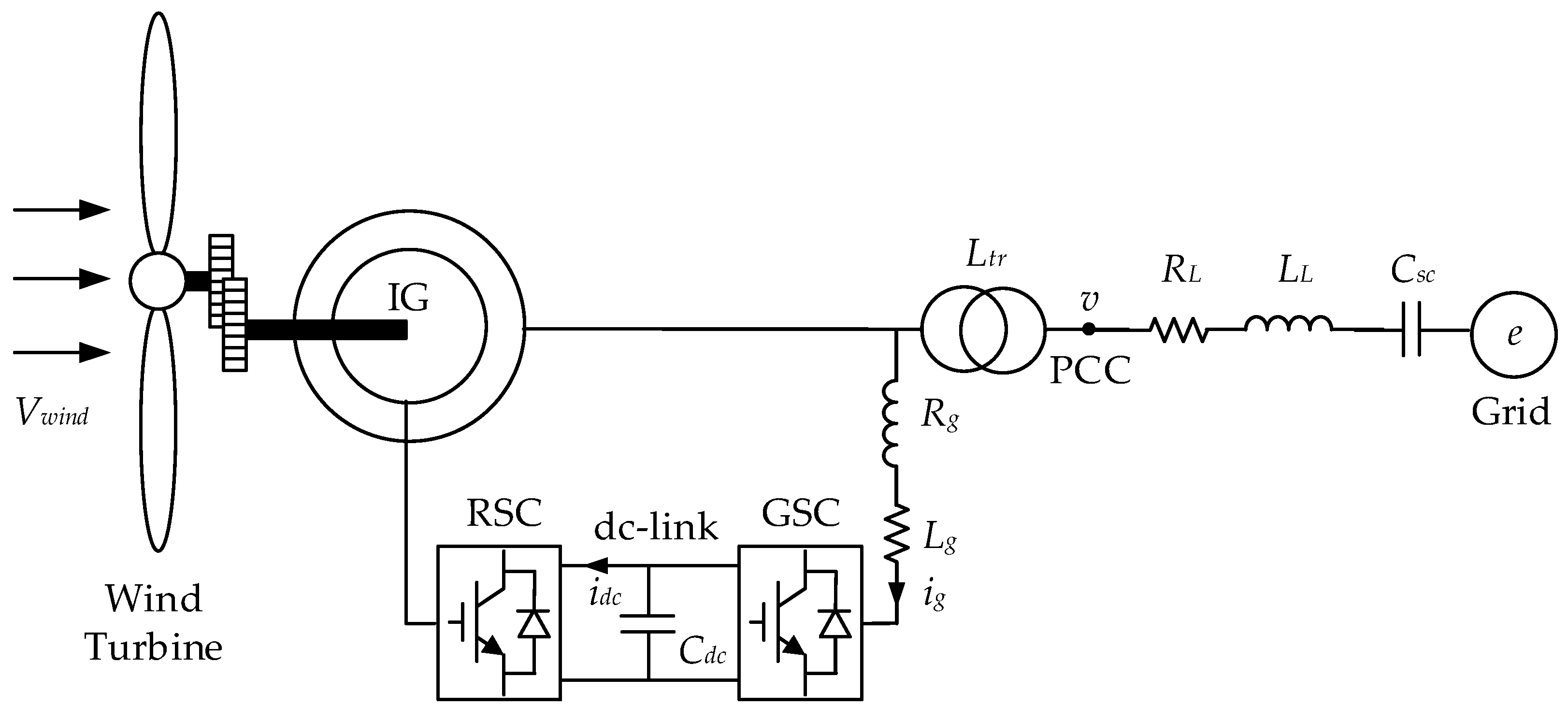
2. Power System Model and PI Controller

For SSCI studies in the paper, a 100 MW DFIG-based wind park is connected to an infinite bus via a 420 kV series-compensated transmission line, as presented in Figure 1 [28]. The 100 MW wind park is an integrated model of 50 wind turbine units, where every unit has a 2 MW power rating. This simplification is verified by the literature [6,32]. The parameters of the system are shown in Appendix A [28].

2.1. DFIG Model

The model for DFIGs is presented in Equations (1) and (2) with reference to the dq reference frames [33]:
{ v sd = R s i s d ω 1 ψ s q + d ψ s d d t v s q = R s i s q + ω 1 ψ s d + d ψ sq d t v rd = R r i rd ω slip ψ rq + d ψ r d d t v rq = R r i rq + ω slip ψ rd + d ψ rq d t
{ ψ s d = L s i s d L m i r d ψ s q = L s i s q L m i r q ψ r d = L m i s d + L r i r d ψ r q = L m i s q + L r i r q
where ωslip = ω1ωr is the slip angular frequency. R s , L s , and L r represent the equivalent stator resistance, equivalent stator inductance, and equivalent rotor inductance considering the transmission line resistance RL, transmission line inductance LL, and compensator capacitance Csc, which can be expressed as [32]:
R s = R s + R L + R g ,   L s = L l s + L t r + L L + L g 1 / ( ω 1 2 C s c ) ,   L r = L r L m 2 / L s .
In the study, the control strategy for the DFIGs is based on vector control, which is oriented to the stator voltage. Thus, the rotor voltage can be expressed as follows [32]:
{ v rd = R r i rd + L r d i rd d t ω slip L r i rq + L m L s [ V s R s i s d + ω 1 ( L s i s q + L m i r q ) ] v rq = R r i rq + L s d i rq d t + ω slip L r i rd + L m L s [ R s i s q ω 1 ( L s i s d + L m i r d ) ]
The stator output active power Ps and the stator output reactive power Qs can be described as:
P s = 3 L m 2 L s V s i r d Q s = 3 V s 2 ω 1 L s ( V s + ω 1 L m i r q )

2.2. GSC Model

The model for GSC is presented in Equation (5) with reference to the dq reference frames [31]:
{ v gd = R g i gd L g d i gd d t ω 1 L g i gq + e d v gq = R g i gq L g d i gq d t ω 1 L g i gd + e q C dc d v dc d t = 3 2 ( S d i gd + S q i gq ) i dc
where vdc is the dc-link voltage across Cdc. R g and L g represent the equivalent resistance and inductance of the filter of the GSC considering RL, LL, and Csc, which can be expressed as:
R g = R g + R L ,   L g = L g + L L 1 / ( ω 1 2 C s c )
In the study, the control strategy for the GSC is based on vector control, which is oriented to the grid voltage. Thus, the reactive power and active power of the GSC can be expressed as follows:
P g = 3 2 V s i g d Q g = 3 2 V s i g q

2.3. PI Controller

As for the PI controller for RSC, the control strategy is based on vector control, which is oriented to the stator flux. Thus, the rotor voltage with reference to the dq reference frames can be expressed as follows [33]:
{ v rd = R r Δ i rd L r ω slip Δ i rq + L r p Δ i rd v rq = R r Δ i rq + L r ω slip Δ i rd + L r p Δ i rq
where Δ i rd = Δ i sd / a , Δ i rq = Δ i sq / a , a = L m / L s , and p is differential operator. The block diagram of the classical PI controller for RSC is illustrated in Figure 2. kg1, kg2, ki1, and ki2 are the PI parameters, which are given in Appendix A. The GSC controller is also implemented utilizing a similar PI control strategy.
The fundamentals of SSCI are explained in [9,32]. The relationship of frequency, speed, and generator parameters can be approximated as follows [32]:
R wtg = R s + R r / ( ω 1 ω m )
where Rwtg is the effective resistance of the generator at the stator to positive-sequence component of the current and ωm is the generator mechanical speed. Under sub-synchronous conditions, the effective rotor resistance R r / ( ω 1 ω m ) will be negative due to higher mechanical speed. Thus, Rwtg may become negative considering the rotor portion. In terms of DFIG, predominant linear PI control schemes always involve a fast-acting current control loop on both RSC (shown in Figure 2) and GSC. The current control loop of GSC has a positive effect on SSCI for it brings about a positive effective grid-side resistance. However, the current control loop of RSC results in an increase in resistance on the rotor side, which results in a negative damping effect, as observed from its stator. Considering the restrictions of a linear controller, an exact feedback linearization (EFL) controller is proposed in this paper.

3. Feedback Linearizability of DFIG-Based Wind Park

3.1. Feedback Linearizability of DFIG

To carry out the feedback linearization of DFIG, it is necessary to conduct nonlinear algebraic operations. Equation (3) is expressed in the classical form of the nonlinear systems with state variables x, control objectives y, and control inputs u:
d x d t = f ( x ) + g 1 ( x ) u 1 + g 2 ( x ) u 2 y 1 = h 1 ( x ) y 2 = h 2 ( x )
where x = [ird irq]T, u = [vrd vrq]T, and y = [ P s P s * Q s Q s * ]T. The values of g(x) and f(x) are presented in Appendix B.
The computation of the relative degree determines the feedback linearizability of the nonlinear system. If the relative degree is equal to the order of the nonlinear system, then the studied system is capable of being exactly linearized.
The relative degree of the nonlinear system can be obtained from matrix D, the rank of which is equal to the relative degree. D is expressed as follows [31]:
D = [ g 1 g 2 a d f g 1 a d f g 2 ]
The process of the calculation of D is shown in Appendix C. The expression of D indicates that rank (D) = 2 and that the linearization condition is satisfied. Thus, the model of the DFIG can be exactly linearized, and the EFL method is employed to design RSC controller to mitigate SSCI.

3.2. Feedback Linearizability of GSC

The model for the GSC (5) is expressed in the classical form of the nonlinear system with state variables x ˜ , control objectives y ˜ , and control inputs u ˜ :
d x ˜ d t = f ˜ ( x ˜ ) + g ˜ 1 ( x ˜ ) u ˜ 1 + g ˜ 2 ( x ˜ ) u ˜ 2 y ˜ 1 = h ˜ 1 ( x ˜ ) y ˜ 2 = h ˜ 2 ( x ˜ )
where x ˜ = [igd igq]T, u ˜ = [vgd vgq]T, and y ˜ = [ v d c v d c * Q g Q g * ]T. The values of g ˜ ( x ˜ ) and f ˜ ( x ˜ ) are presented in Appendix B.
The relative degree of the GSC is expressed as follows:
D ˜ = [ g ˜ 1 g ˜ 2 a d f ˜ g ˜ 1 a d f ˜ g ˜ 2 ]
The process of the calculation of D ˜ is shown in Appendix C. The expression of D ˜ indicates that rank( D ˜ ) = 2, and the linearization condition is satisfied. Thus, the model of the GSC can be exactly linearized and the EFL method is utilized to design a GSC controller to mitigate SSCI.

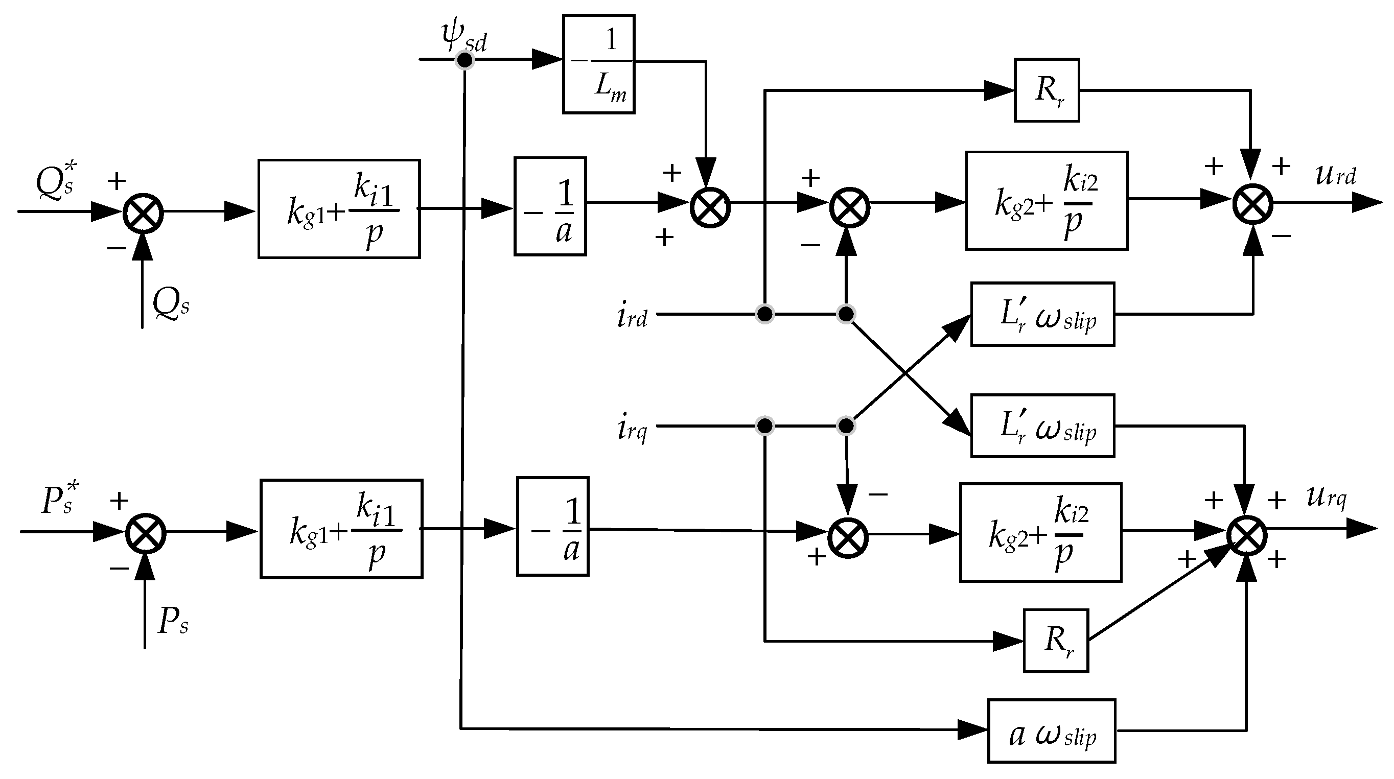
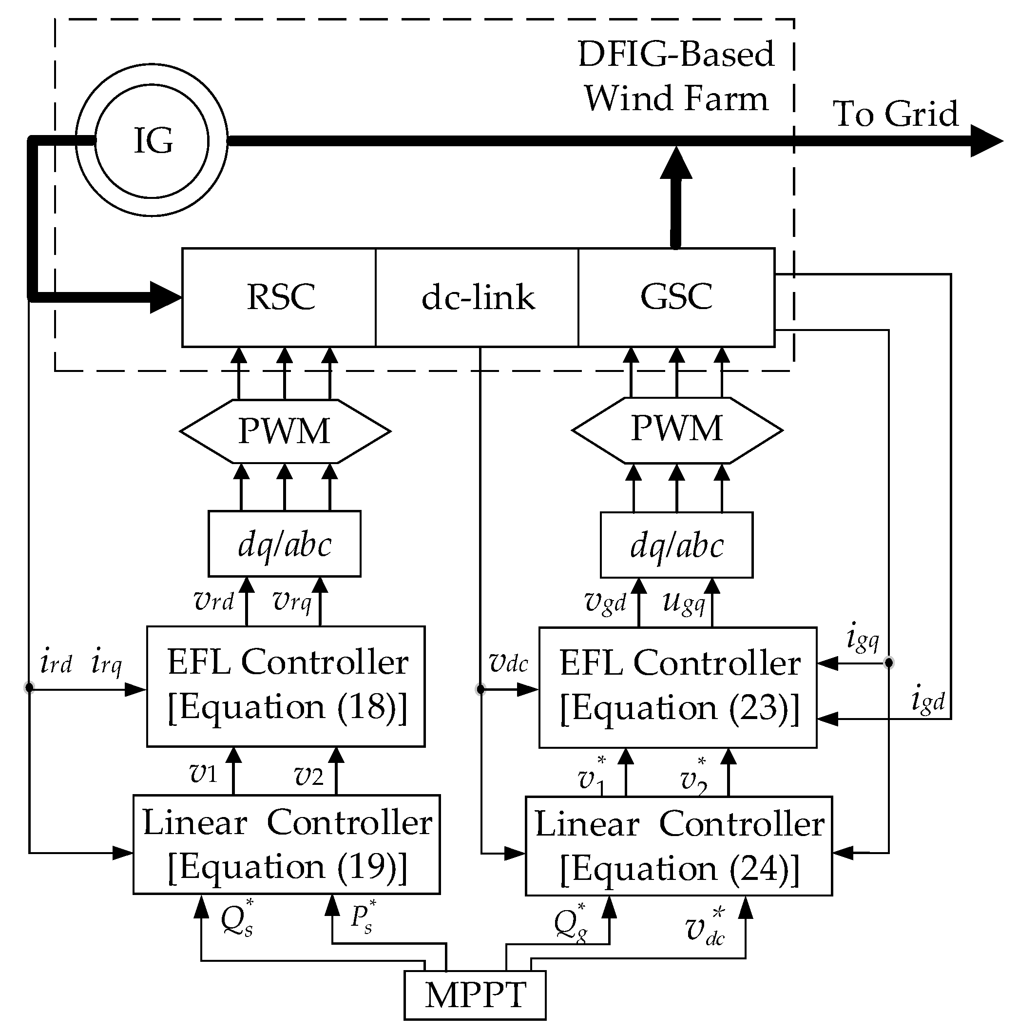
4. Design of Exact Feedback Linearizing Controllers

The design process of the EFL controllers for the studied system is presented in this section. Exact feedback linearization converts the nonlinear system into the linear one, as:
d z d t = A z + B v
where z is the new state variables, which are converted via nonlinear coordination transformation; v is the control input; A is the system matrix; and B is the input matrix. The new state variables are derived through the following coordinate conversion:
z i = L f i 1 h i ( x )
where i = 1, 2, …, n and L defines the Lie derivative concerning the corresponding subscripts. For instance, L f i 1 h i ( x ) is the (ri − 1)th Lie derivative of h i ( x ) concerning f ( x ) , where ri represents the relative degree of the ith output.

4.1. RSC Controller Design

For the model of the DFIG, we choose
z 1 = f 1 ( x ) = h 1 ( x ) = 3 L m 2 L s V s i r d P s * z 2 = f 2 ( x ) = h 2 ( x ) = 3 V s 2 ω 1 L s ( V s + ω 1 L m i r q ) Q s *
then we have
d z 1 d t = h 1 ( x ) x d x d t = 3 L m V s 2 L s f 1 + 3 L m V s 2 L s L r u 1 d z 2 d t = h 2 ( x ) x d x d t = 3 L m V s 2 L s f 2 3 L m V s 2 L s L r u 2
Applying a linear control technique as d z ˜ i / d t = v ˜ i , the linearized form of the DFIG is obtained:
v 1 = 3 L m V s 2 L s f 1 + 3 L m V s 2 L s L r u 1 v 2 = 3 L m V s 2 L s f 2 3 L m V s 2 L s L r u 2
where v1 and v2 are the linear control inputs, which could be derived by utilizing linear control theory. The control inputs u1 and u2 are calculated by Equation (17):
u 1 = R r i r d ω s l i p L r i r q ω s l i p L m L s ( L s i s q + L m i r q ) L m L s [ V s R s i s d + ω 1 ( L s i s q + L m i r q ) ] + 2 L s L r 3 L m V s v 1 u 2 = R r i r q + ω s l i p L r i r d + ω s l i p L m L s ( L s i s d + L m i r d ) + L m L s [ R s i s q ω 1 ( L s i s d + L m i r d ) ] 2 L s L r 3 L m V s v 2
The linear control inputs v1 and v2 are obtained through linear optimal control:
v 1 = z 1 = P s * P s = P s * 3 L m 2 L s V s i r d v 2 = z 2 = Q s * Q s = Q s * + 3 V s 2 ω 1 L s ( V s + ω 1 L m i r q )

4.2. GSC Controller Design

For the model of the GSC, we choose
z ˜ 1 = f 1 ˜ ( x ˜ ) = h ˜ 1 ( x ˜ ) = v d c V d c z ˜ 2 = f 2 ˜ ( x ˜ ) = h ˜ 2 ( x ˜ ) = 3 2 V s i g q Q g *
then we have
d z 1 ˜ d t = h 1 ˜ ( x ˜ ) x ˜ d x ˜ d t = 3 V s 2 C d c V d c f 1 ˜ 3 V s 2 C d c V d c L g u ˜ 1 d z 2 ˜ d t = h ˜ 2 ( x ˜ ) x ˜ d x ˜ d t = 3 V s 2 f 2 ˜ + 3 V s 2 L g u ˜ 2
Applying linear control technique as d z i / d t = v i , the linearized form of the GSC is obtained:
v ˜ 1 = 3 V s 2 C d c V d c f 1 ˜ 3 V s 2 C d c V d c L g u ˜ 1 v ˜ 2 = 3 V s 2 f 2 ˜ + 3 V s 2 L g u ˜ 2
where v ˜ 1 and v ˜ 2 are the linear control inputs, which could be obtained by utilizing linear control theory. The control inputs u ˜ 1 and u ˜ 2 of the system are calculated by Equation (22):
u ˜ 1 = R g i g d + ω 1 i g q + V s 2 C d c v d c L g 3 V s v 1 u ˜ 2 = ω 1 i g d R g i g q + 2 L g 3 V s v 2
The linear control inputs v ˜ 1 and v ˜ 2 are obtained through linear optimal control:
v ˜ 1 = z ˜ 1 = v d c * v d c v ˜ 2 = z ˜ 2 = Q g * Q g

5. Time-domain Simulation Results and Analysis

The simulation results and analysis of the designed controllers of SSCI alleviation in the system are discussed in the section. The block diagram of the RSC and GSC control strategy utilizing the EFL method is illustrated in Figure 3.
In terms of the RSC controller, it is observed that P s * , Q s * , ird, and irq are imported into the linear controller (19), which presents the control law (18) in the dq frame. Eventually, dq/abc transformation is carried out for control scheme implementation by pulse width modulator (PWM). The implementation process of the GSC controller is similar to that of the RSC controller.
For the verification of the effectiveness of the proposed EFL controllers in SSCI alleviation, frequency scanning analysis is employed. Moreover, time-domain simulations and eigenvalue analysis are performed to check the correctness of the results derived by frequency scanning analysis.

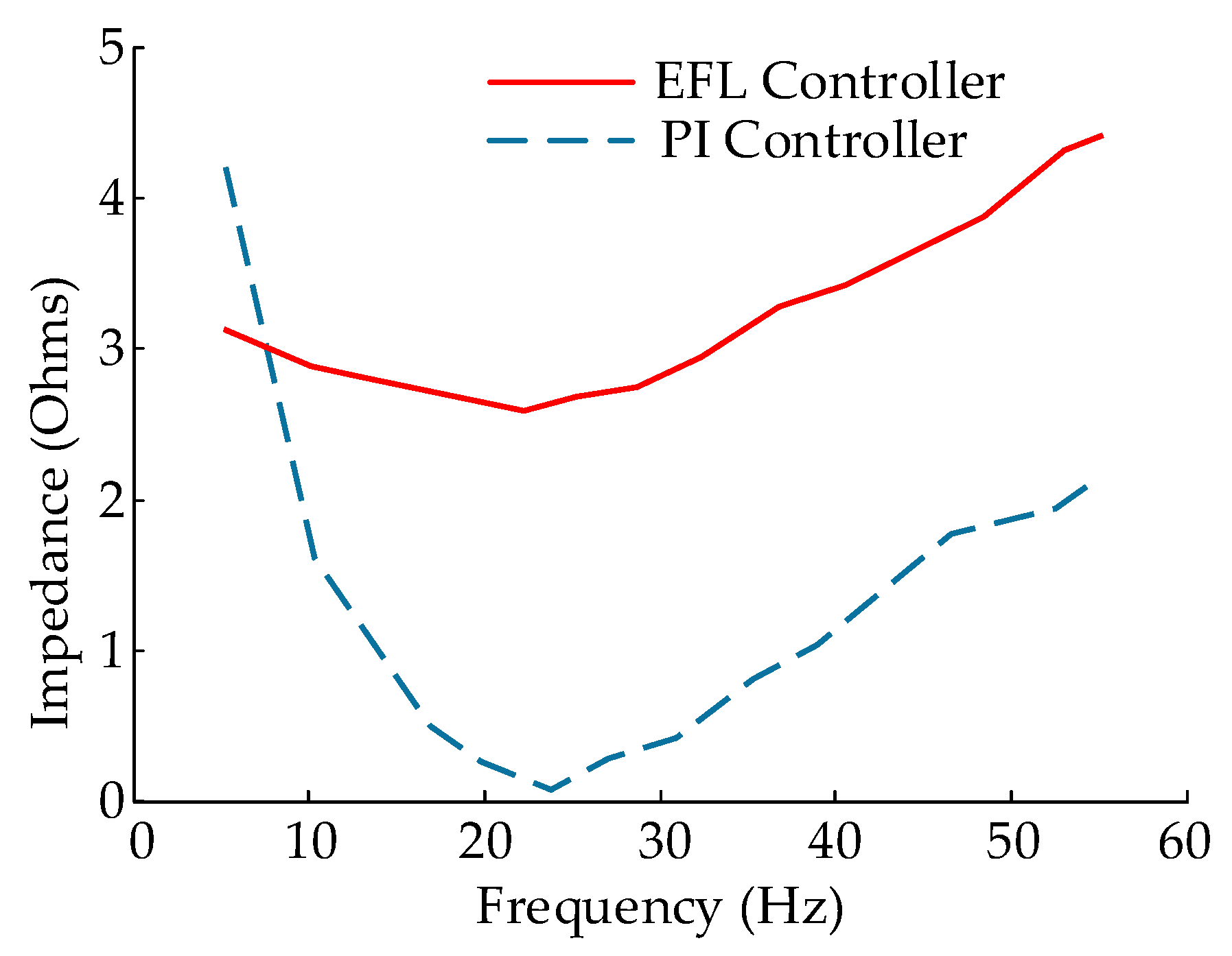
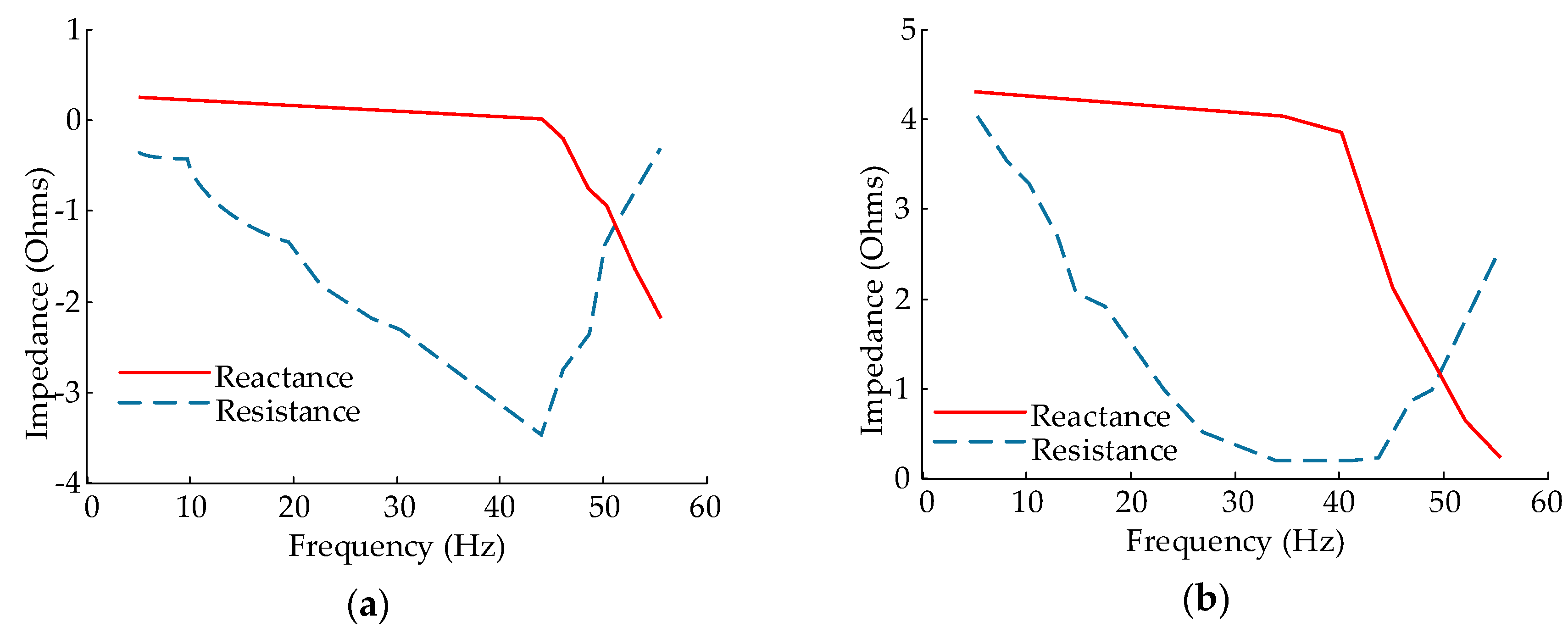
5.1. Frequency Scanning Analysis

To carry out frequency scanning analysis of SSCI in the studied system, the positive sequence component of the sub-synchronous voltage, einject, has to be superimposed on the fundamental frequency excitation. We choose a voltage injection instead of current one, which can be ascribed to two factors: (i) the injected signal of voltage injection is less sensitive to variation compared to that of current injection; and (ii) voltage injection produces a smaller disturbance at the operating point than current injection. Thus, einject is put in series with the source voltage, vsource at the bus bar. Owing to the injected voltage, we can obtain the desired harmonic impedance, Zharmonic, which is utilized for frequency scanning. The harmonic impedance under different frequencies as observed from the DFIG terminal can be evaluated based on Fourier analysis. Therefore, under sub-synchronous conditions, the DFIG harmonic impedance can be calculated [26]:
Z h a r m o n i c = F [ v s o u r c e + e i n j e c t ( Z L + Z t r ) i s o u r c e ] F ( i s o u r c e )
where isource represents the source current, Z t r = j ω L t r represents the impedance of the transformer, Z L = R L + j ω L L + ( 1 / j ω C s c ) represents the line impedance, and F denotes the Fourier transformation.
In frequency scanning analysis, Zharmonic is calculated via harmonic injection looking from the system side and the turbine side. It is necessary to correlate the consequences from frequency scanning in each side for a risk evaluation of SSCI problems.
The system side scan observed from behind the wind park at the compensation level of 70% is presented in Figure 4. A distinct resonant frequency with PI controllers is seen at about 23 Hz, which is recognized from the impedance sag close to zero. A sag in the magnitude of Z h a r m o n i c indicates a zero reactance coincidence with a negative resistance.
In Figure 5a, the apparent impedance is decoupled into corresponding reactance and resistive components. From the figure, it is obvious that the apparent resistance of the turbine is negative under sub-synchronous frequency conditions, whereas zero crossover of the reactance is seen at approximately 44 Hz, which is far from resonant frequency of the system. This observation indicates the non-existence of other types of SSR phenomenon.
The frequency scanning analysis is also carried out with the incorporation of the proposed EFL controller. From Figure 4, there is no obvious impedance sag seen from system side scan. On the other hand, turbine side scanning shows that the apparent reactance and resistance of the turbine are positive over the whole sub-synchronous frequency range, as demonstrated in Figure 5b. Therefore, it is obvious that the proposed EFL controllers effectively alleviate the SSCI effect in the studied system.

5.2. Eigenvalue Analysis

The system mode is a pair of eigenvalues, expressed as λ = σ ± j ω . The oscillation frequency of the system mode is f = ω / 2 π , and its positive real part suggests an unstable operation due to the negative damping. Three system modes are studied in this paper, and they are computed from the linearized system matrices. Modes 1, 2, and 3 represent a super-synchronous mode, a sub-synchronous mode, and an electromechanical mode, respectively. Compensation level K is defined as K = ( 1 / ω C s c ) / ω L L .
Since the studied system is established with respect to synchronous reference, the super-synchronous mode has an oscillation frequency of ( 60 + f n ) observed from a synchronous rotating frame (where fn represents the natural frequency of electrical system). This mode is unimportant to SSCI studies. This statement holds true for the electromechanical mode, which has links with rotor speed dynamics and rotor circuit dynamics. The oscillation frequency of the sub-synchronous mode is ( 60 f n ) when stationary circuits are seen from a synchronous reference. In eigenvalue analysis, the identification of sub-synchronous mode is of most significance.
Table 1 presents the three studied modes with changing wind speed (Vwind). The modes considering the varying compensation levels (K) are shown in Table 2. In the tables, the resonance mode of the system has a oscillation frequency of about 23.6 Hz, seen from a synchronous reference frame at a 70% compensation level and 8 m/s wind speed, which corresponds to the results observed from the frequency scanning analysis. Moreover, both the electromechanical mode and the super-synchronous mode correspond to the modes identified. For the sub-synchronous mode, it is concluded that (i) the higher the compensation level and (ii) the lower the wind speed, the less the damping of system modes.
The unstable sub-synchronous modes are recognized as presented in the tables (highlighted in bold lettering). With the adoption of the EFL controllers, the system generally preserves stability through the accomplishment of negative σ by the sub-synchronous mode, except for rather high compensation levels.

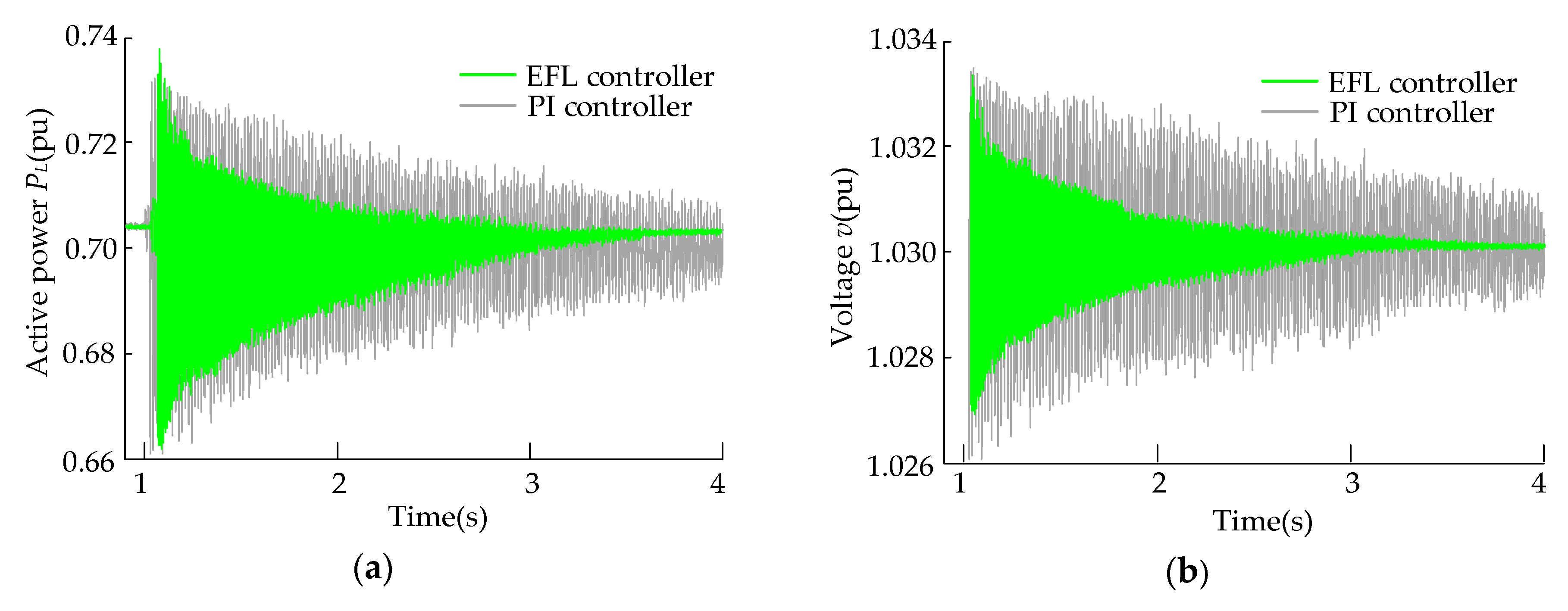
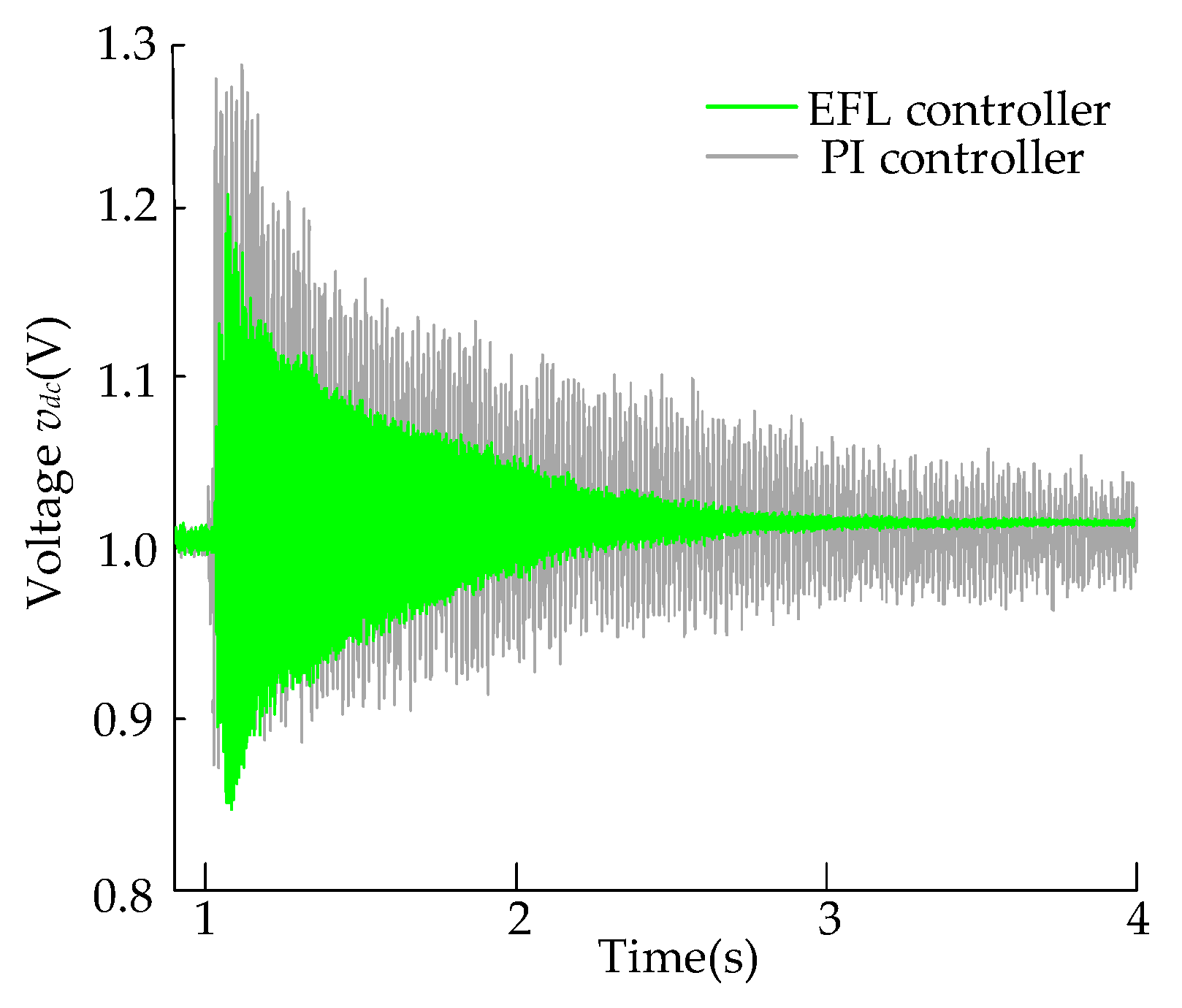
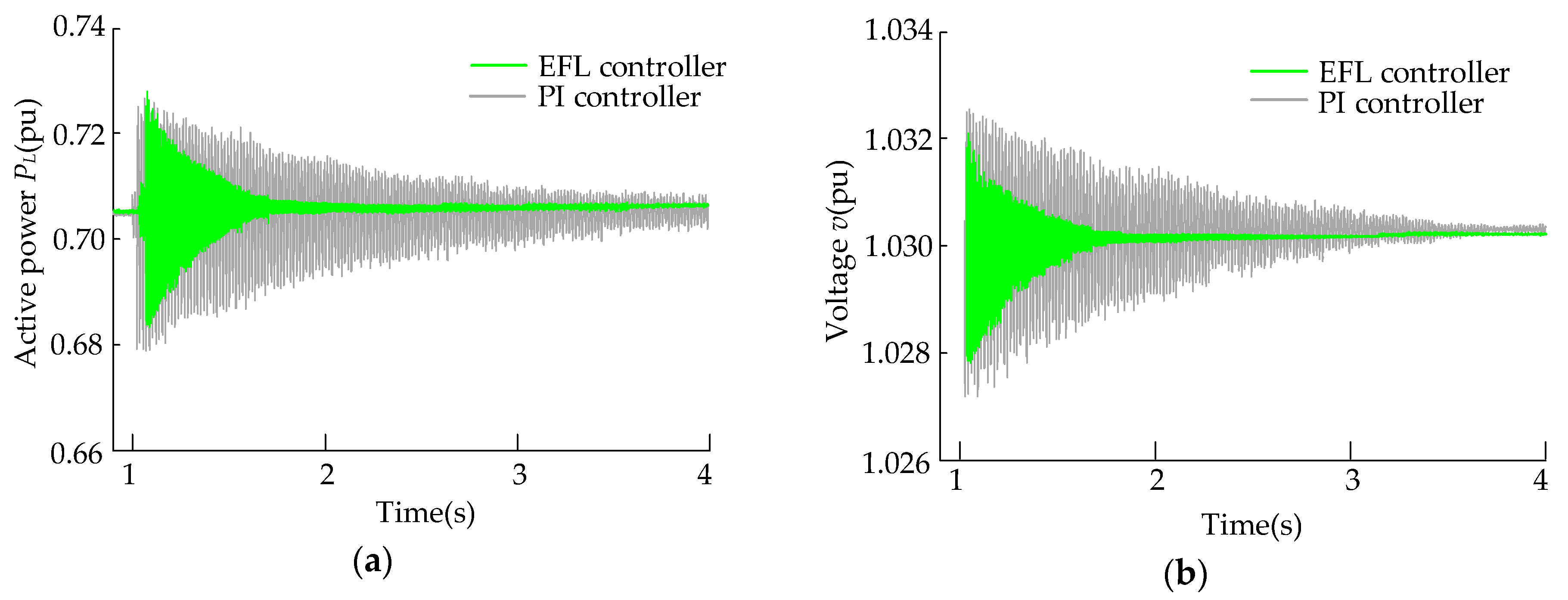
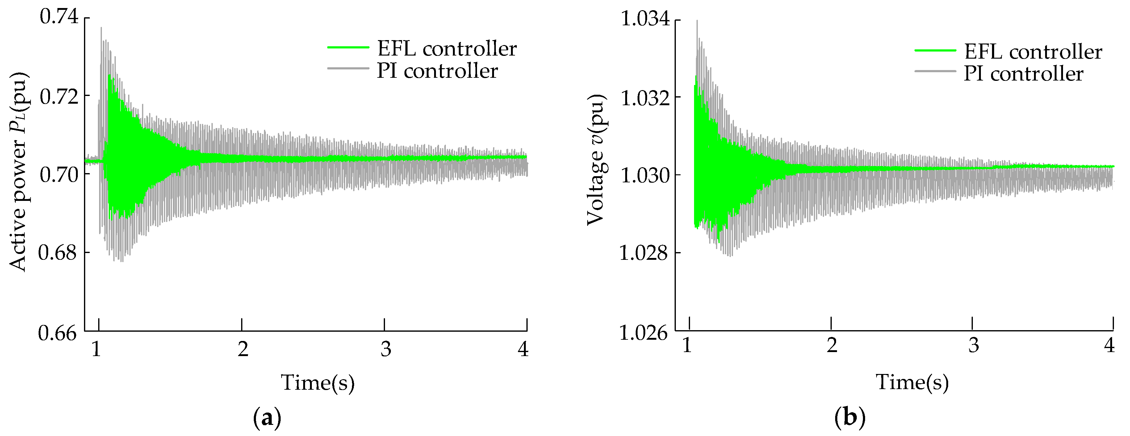
5.3. Time-Domain Simulations and Analysis

In this section, the performance of the designed EFL controllers for GSC and RSC in alleviating SSCI is evaluated by simulations utilizing MATLAB/SimpowerSystem and compared to classical linear PI controllers. SimpowerSystem (or Simscape Power System) is the toolbox that provides time-domain simulations. The model of the studied DFIG-based wind park is based on one of the wind farm demonstrations in MATLAB (SimPowerSystems/Demos/Distributed Resources Models/DFIG Detailed Model), and the structure and the parameters are adjusted according to our requirements. The EFL controllers for the GSC and RSC are encapsulated in a control subsystem block, which is inserted into the DFIG model. Since the previous DFIG model is modified and the prior controller is replaced by the proposed EFL controller, we have to regenerate the initial conditions so that the simulation starts in steady-state. For the comparison between PI controllers and EFL controllers, some case studies are implemented.
At t = 1 s, a wind speed of 8 m/s and a series-compensation of 70% are applied to the transmission line. The condition of wind speed is justified since the prevailing oscillation in the DFIG-based wind park owing to series-compensation fluctuates far faster.
Responses from the system are monitored, which include transmission line active power (PL) and the point of common coupling (PCC) voltage (v). From Figure 6, it is observed that an SSCI problem still exists in the DFIG-based wind park with PI controllers after 4 s, whereas SSCI is observed to be damped with EFL controllers within 3.6 s.
The effectiveness of EFL controllers in mitigating the fluctuation of DC-link voltage (vdc) is evaluated as well. As is shown in Figure 7, the maximum value that the DC-link voltage has peaked at is approximately 1.2 pu with the EFL controller, whereas the DC-link voltage peaks at about 1.3 pu with the use of PI controllers. Furthermore, the use of EFL controllers has managed to reduce the voltage fluctuation range of the DC-link to the nominal value after 3 s. By contrast, the PI controller cannot effectively mitigate the fluctuations, even after 4 s.
The simulations are also repeated at a series-compensation level of 40% (wind speed 8 m/s) and a wind speed of 10 m/s (series-compensation of 70%), respectively. It is shown in Figure 8 and Figure 9 that the proposed EFL controllers significantly improve the system stability compared to conventional finely tuned PI controllers. Moreover, SSCI is damped better for lower compensation levels and higher wind speeds, which supports the observation in the eigenvalue analysis.

6. Conclusions

In order to mitigate sub-synchronous control interaction in the series-compensated DFIG-based wind parks, this paper proposes nonlinear controllers based on an exact feedback linearization (EFL) technique. The design procedures of the proposed control scheme involve scrutinizing the exact linearizability, performing exact feedback linearization on the studied system, and obtaining control laws for the RSC and GSC.
Frequency scanning analysis is conducted to assess the effectiveness of the proposed EFL controllers in comparison with classical linear PI controllers. It is observed that EFL controllers have superior performance in terms of SSCI mitigation. In order to validate the results derived from the frequency scanning method and to further verify the effectiveness of the proposed EFL controllers, an eigenvalue analysis and a time-domain simulation are performed as well. Through the eigenvalue analysis, several unstable sub-synchronous modes are identified with the adoption of PI controllers. On the contrary, the studied system with the EFL controllers is generally capable of retaining stability unless the compensation is too high. Moreover, the time-domain simulation indicates that prevailing SSCI in the DFIG-based system with PI controllers can be alleviated by utilizing the proposed EFL controllers.
The EFL controller is an economical and feasible systematic enhancement for GSC and RSC in DFIG. With the adoption of an EFL controller, the dynamics of the studied system can be described more precisely, and the inherent nonlinearities of the DFIGs can be retained as much as possible, thereby achieving the mitigation of SSCI.

Acknowledgments

This work is supported by the National Natural Science Foundation of China (Grant No. 61374155).

Author Contributions

Penghan Li validated the model, designed the simulation, implemented the proposed the technique and strategy, and wrote the paper; Linyun Xiong performed the experiments; Fei Wu analyzed the data; and Jie Wang modified the structure and polished the language of the paper.

Conflicts of Interest

The authors declare no conflict of interest.

Nomenclature

ParameterSymbol
Voltagev
Currenti
Flux linkageψ
ResistanceR
InductanceL
Grid voltagee
Stator, rotor angular frequenciesω1, ω
Mutual inductanceLm
Transmission line resistanceRL
Transmission line inductanceLL
Compensator capacitanceCsc
DC-link capacitanceCdc
Magnitude of the stator voltage vectorVs
Active power, reactive powerP, Q
Input switching signals for the grid side converterS
Subscripts
Stator, rotors, r
d-axis, q-axisd, q
Grid side converter loopg
Superscripts
Equivalent value
Reference value*

Appendix A

Table A1. System parameters.
ParameterSymbolValueUnit
Nominal voltage (line to line)VL-L690V
Nominal powerP100MW
Stator resistanceRs0.0084p.u.
Rotor resistanceRr0.0083p.u.
Stator leakage inductanceLls0.167p.u.
Rotor self-inductanceLlr0.1323p.u.
Mutual inductanceLm5.419p.u.
dc-link capacitanceCdc10mF
Nominal dc-link voltagevdc1200V
Compensator capacitanceCsc10mF
Transmission line resistanceRL0.02p.u.
Transmission line inductanceLL0.0016p.u.
Table A2. PI parameters of the rotor side converter.
ParameterValue
kg10.01
ki10.10
kg20.10
ki21.00

Appendix B

The values of g(x) and f(x)
g 1 ( x ) = [ 1 / L r 0 ] , g 2 ( x ) = [ 0 1 / L r ] , f ( x ) = [ f 1 ( x ) f 2 ( x ) ]
f 1 ( x ) = R r L r i r d + ω s l i p i r q + ω s l i p L m L s L r ( L s i s q + L m i r q ) L m L s L r [ V s R s i s d + ω 1 ( L s i s q + L m i r q ) ]
f 2 ( x ) = R r L r i r q ω s l i p i r d ω s l i p L m L s L r ( L s i s d + L m i r d ) L m L s L r [ R s i s q ω 1 ( L s i s d + L m i r d ) ]
The values of f ˜ ( x ˜ ) and g ˜ ( x ˜ )
g ˜ 1 ( x ˜ ) = [ 1 / L g 0 ] , g ˜ 2 ( x ˜ ) = [ 0 1 / L g ] , f ˜ ( x ˜ ) = [ f 1 ˜ ( x ˜ ) f 2 ˜ ( x ˜ ) ] = [ R g L g i g d + ω 1 i g q + 1 L g V s R g L g i g q ω 1 i g d ]

Appendix C

The calculation of D and D ˜
D = [ g 1 g 2 a d f g 1 a d f g 2 ]
where
a d f g 1 = g 1 x f f x g 1 = [ R r ( L r ) 2 ω s l i p L r L m 2 ( L r ) 2 ω r L s ]   a d f g 2 = g 2 x f f x g 2 = [ ω s l i p L r + L m 2 ( L r ) 2 ω r L s R r ( L r ) 2 ]
then D is obtained:
D = [ 1 L r 0 R r ( L r ) 2 ω s l i p L r + L m 2 ( L r ) 2 ω r L s 0 1 L r ω s l i p L r L m 2 ( L r ) 2 ω r L s R r ( L r ) 2 ]
D ˜ = [ g ˜ 1 g ˜ 2 a d f ˜ g ˜ 1 a d f ˜ g ˜ 2 ]
where
a d f ˜ g ˜ 1 = g ˜ 1 x ˜ f ˜ f ˜ x ˜ g ˜ 1 = [ R g ( L g ) 2 ω 1 L g ]   a d f ˜ g ˜ 2 = g ˜ 2 x ˜ f ˜ f ˜ x ˜ g ˜ 2 = [ ω 1 L g R g ( L g ) 2 ]
then D ˜ is obtained:
D ˜ = [ 1 L g 0 R g ( L g ) 2 ω 1 L g 0 1 L g ω 1 L g R g ( L g ) 2 ]

References

  1. Chowdhury, M.A.; Shen, W.X.; Hosseinzadeh, N.; Pota, H.R. A novel aggregated DFIG wind farm model using mechanical torque compensating factor. Energy Conver. Manag. 2013, 67, 265–274. [Google Scholar] [CrossRef]
  2. Thomas, A. Wind Power in Power Systems; John Wiley & Sons, Ltd: West Sussex, UK, 2005. [Google Scholar]
  3. Mahmud, M.A.; Pota, H.R.; Hossain, M.J. Dynamic Stability of Three-Phase Grid-Connected Photovoltaic System Using Zero Dynamic Design Approach. IEEE J. Photovolt. 2012, 2, 564–571. [Google Scholar] [CrossRef]
  4. Mohammadpour, H.A.; Santi, E. SSR Damping Controller Design and Optimal Placement in Rotor-Side and Grid-Side Converters of Series-Compensated DFIG-Based Wind Farm. IEEE Trans. Sustain Energy 2015, 6, 388–399. [Google Scholar] [CrossRef]
  5. Wang, L.; Xie, X.; Jiang, Q.; Liu, H.; Li, Y.; Liu, H. Investigation of SSR in Practical DFIG-Based Wind Farms Connected to a Series-Compensated Power System. IEEE Trans. Power Syst. 2015, 30, 2772–2779. [Google Scholar] [CrossRef]
  6. Mohammadpour, H.A.; Santi, E. Sub-synchronous resonance analysis in DFIG-based wind farms: Definitions and problem identification—Part I. In Proceedings of the 2014 IEEE Energy Conversion Congress and Exposition (ECCE), Pittsburgh, PA, USA, 14–18 September 2014. [Google Scholar]
  7. Padiar, K.R. Analysis of Sub-Synchronous Resonance in Power Systems; Kluwer Academic Publishers (KAP): Boston, MA, USA, 1999. [Google Scholar]
  8. IEEE SSR Working Group. Terms, definitions and symbols for subsynchronous oscillations. IEEE Trans. Power Appl. Syst. 1985, 6, 1326–1334. [Google Scholar]
  9. Gross, L.C. Sub-Synchronous Grid Conditions: New Event, New Problem, and New Solutions. In Proceedings of the Western Protective Relay Conference, Spokane, WA, USA, 19–21 October 2010. [Google Scholar]
  10. Sahni, M.; Badrzadeh, B.; Muthumuni, D.; Cheng, Y.; Yin, H.; Huang, S. Sub-synchronous interaction in Wind Power Plants part II: An ERCOT case study. In Proceedings of the 2012 IEEE Power and Energy Society General Meeting, San Diego, CA, USA, 22–26 July 2012. [Google Scholar]
  11. Irwin, G.D.; Jindal, A.K.; Isaacs, A.L. Sub-Synchronous Control Interactions between Type 3 Wind Turbines and Series Compensated AC Transmission Systems. In Proceedings of the 2011 IEEE Power and Energy Society General Meeting, Detroit, MI, USA, 24–29 July 2011. [Google Scholar]
  12. Kidd, D.; Hassink, P. Transmission Operator Perspective of SubSynchronous Interaction. In Proceedings of the 2012 IEEE PES Transmission and Distribution Conference and Exposition (T&D), Orlando, FL, USA, 7–10 May 2012. [Google Scholar]
  13. Hingorani, N.G.; Gyugi, L. Understanding FACTS; IEEE Press: Piscataway, NJ, USA, 2000. [Google Scholar]
  14. Adrees, A.; Milanović, J.V. Optimal Compensation of Transmission Lines Based on Minimisation of the Risk of Subsynchronous Resonance. IEEE Trans. Power Syst. 2016, 31, 1038–1047. [Google Scholar] [CrossRef]
  15. Gupta, S.K.; Gupta, A.K.; Kumar, N. Damping subsynchronous resonance in power systems. IEE Proc. Gener. Transm. Distrib. 2002, 149, 679–688. [Google Scholar] [CrossRef]
  16. Daneshpooy, A.; Gole, A.M. Frequency response of the thyristor controlled series capacitor. IEEE Trans. Power Del. 2001, 16, 53–58. [Google Scholar] [CrossRef]
  17. Mohammadpour, H.A.; Ghaderi, A.; Santi, E. Analysis of SSR in DFIG-based wind farms interfaced with gate-controlled series capacitor. IET Gener. Transm. Dis. 2014, 8, 1998–2011. [Google Scholar] [CrossRef]
  18. El Moursi, M.S.; Khadkikar, V. Novel control strategies for SSR mitigation and damping power system oscillations in a series compensated wind park. In Proceedings of the IECON 2012—38th Annual Conference on IEEE Industrial Electronics Society, Montreal, QC, Canada, 25–28 October 2012. [Google Scholar]
  19. Rajaram, T.; Reddy, J.M.; Xu, Y. Kalman Filter Based Detection and Mitigation of Subsynchronous Resonance with SSSC. IEEE Trans. Power Syst. 2017, 32, 1400–1409. [Google Scholar]
  20. Fan, L.; Miao, Z. Mitigating SSR Using DFIG-Based Wind Generation. IEEE Trans. Sustain. Energy 2012, 3, 349–358. [Google Scholar] [CrossRef]
  21. Leon, A.E. Integration of DFIG-Based Wind Farms into Series-Compensated Transmission Systems. IEEE Trans. Sustain. Energy 2016, 7, 451–460. [Google Scholar] [CrossRef]
  22. Faried, S.O.; Unal, I.; Rai, D.; Mahseredjian, J. Utilizing DFIG-Based Wind Farms for Damping Subsynchronous Resonance in Nearby Turbine-Generators. IEEE Trans. Power Syst. 2013, 28, 452–459. [Google Scholar] [CrossRef]
  23. Huang, P.H.; Moursi, M.S.E.; Xiao, W.; Kirtley, J.L. Subsynchronous Resonance Mitigation for Series-Compensated DFIG-Based Wind Farm by Using Two-Degree-of-Freedom Control Strategy. IEEE Trans. Power Syst. 2015, 30, 1442–1454. [Google Scholar] [CrossRef]
  24. Leon, A.E.; Solsona, J.A. Sub-Synchronous Interaction Damping Control for DFIG Wind Turbines. IEEE Trans. Power Syst. 2015, 30, 419–428. [Google Scholar] [CrossRef]
  25. Dattaray, P.; Chakravorty, D.; Wall, P.; Yu, J.; Terzija, V. A Novel Control Strategy for Subsynchronous Resonance Mitigation using 11kV VFD based Auxiliary Power Plant Loads. IEEE Trans. Power Del. 2017, 99, 1. [Google Scholar] [CrossRef]
  26. Liu, H.; Xie, X.; Li, Y.; Liu, H.; Hu, Y. Damping Subsynchronous Resonance in Series Compensated Wind Farms by Adding Notch Filters to DFIG Controllers. In Proceedings of the 2015 IEEE Innovative Smart Grid Technologies—Asia (ISGT Asia), Bangkok, Thailand, 3–6 November 2015. [Google Scholar]
  27. Adams, J.; Carter, C.; Huang, H. ERCOT Experience with Sub-Synchronous Control Interaction and Proposed Remediation. In Proceedings of the 2012 IEEE PES Transmission and Distribution Conference and Exposition (T&D), Orlando, FL, USA, 7–10 May 2012. [Google Scholar]
  28. Chowdhury, M.A.; Mahmud, M.A.; Shen, W.; Pota, H.R. Nonlinear Controller Design for Series-Compensated DFIG-Based Wind Farms to Mitigate Subsynchronous Control Interaction. IEEE Trans. Energy Convers. 2017, 32, 707–719. [Google Scholar] [CrossRef]
  29. Mahmud, M.A.; Pota, H.R.; Hossain, M.J. Nonlinear DSTATCOM controller design for distribution network with distributed generation to enhance voltage stability. Int. J. Electr. Power Energy Syst. 2013, 53, 974–979. [Google Scholar] [CrossRef]
  30. Mahmud, M.A.; Hossain, M.J.; Pota, H.R.; Roy, N.K. Nonlinear Controller Design for Vehicle-To-Grid (V2G) Systems to Enhance Power Quality and Power System Stability. In Proceedings of the 19th IFAC World Congress, Cape Town, South Africa, 24–29 August 2014. [Google Scholar]
  31. Mahmud, M.A.; Hossain, M.J.; Pota, H.R. Robust Nonlinear Distributed Controller Design for Active and Reactive Power Sharing in Islanded Microgrids. IEEE Trans. Energy Convers. 2014, 29, 893–903. [Google Scholar] [CrossRef]
  32. Mohammadpour, H.A.; Santi, E. Modeling and Control of Gate-Controlled Series Capacitor Interfaced with a DFIG-Based Wind Farm. IEEE Trans. Ind. Electron. 2015, 62, 1022–1033. [Google Scholar] [CrossRef]
  33. Gao, B.; Liu, J.; Li, R.; Zhao, S. Studies of Sub-Synchronous Control Interaction in Wind Turbine Generators. Trans. China Electrotech. Soc. 2015, 30, 154–161. [Google Scholar]
Figure 1. Grid-connected series-compensated DFIG wind park.
Energies 10 01182 g001
Figure 2. Implementation block diagram of the PI controller for rotor side converter (RSC).
Energies 10 01182 g002
Figure 3. Block diagram of the proposed RSC and grid side converter (GSC) controllers utilizing exact feedback linearization (EFL) method.
Energies 10 01182 g003
Figure 4. System side scans.
Energies 10 01182 g004
Figure 5. Turbine side scans of wind park: (a) with PI controller; (b) with EFL controller.
Energies 10 01182 g005
Figure 6. System responses at a wind speed of 8 m/s and a series-compensation of 70%: (a) transmission line active power; (b) point of common coupling (PCC) voltage.
Energies 10 01182 g006
Figure 7. DC-link voltage (vdc) at a wind speed of 8 m/s and a series-compensation of 70%.
Energies 10 01182 g007
Figure 8. System responses at a wind speed of 8 m/s and a series-compensation of 40%. (a) Transmission line active power; (b) PCC voltage.
Energies 10 01182 g008
Figure 9. System responses at a wind speed of 10 m/s and for a series-compensation of 70%. (a) Transmission line active power; (b) PCC voltage.
Energies 10 01182 g009
Table 1. System modes for a compensation level (K) of 70%.
Vwind (m/s)Mode 1
EFL
PIMode 2
EFL
PIMode 3
EFL
PI
8−9.1 ± j629.3−8.0 ± j628.8−1.4 ± j147.7+1.9 ± j148.3−16.1 ± j94.9−11.5 ± j94.1
9−8.2 ± j628.9−7.6 ± j628.9−2.9 ± j145.6+0.7 ± j145.0−7.4 ± j58.2−6.8 ± j58.2
10−7.5 ± j627.6−7.3 ± j629.1−5.0 ± j144.2−0.9 ± j141.9−6.2 ± j22.4−5.7 ± j22.2
11−7.1 ± j627.0−6.9 ± j629.0−6.9 ± j143.3−9.9 ± j141.2−4.9 ± j22.0−4.7 ± j21.6
Table 2. System modes at a wind speed (Vwind) of 8 m/s.
K (%)Mode 1
EFL
PIMode 2
EFL
PIMode 3
EFL
PI
30−5.9 ± j524.5−5.5 ± j522.6−4.6 ± j231.1−2.1 ± j230.6−7.0 ± j95.7−4.3 ± j95.1
50−7.9 ± j581.3−6.7 ± j580.0−3.0 ± j173.5−1.5 ± j172.3−9.7 ± j94.5−6.1 ± j95.2
70−9.1 ± j629.3−8.0 ± j628.8−1.4 ± j147.7+1.9 ± j148.3−16.1 ± j94.9−11.5 ± j94.1
90−9.7 ± j653.1−8.8 ± j652.6+3.0 ± j111.2+5.8 ± j109.7−22.0 ± j87.6−16.0 ± j86.4

