
Effects of Mass and Damping on Flow-Induced Vibration of a Cylinder Interacting with the Wake of Another Cylinder at High Reduced Velocities


Center for Turbulence Control, Harbin Institute of Technology (Shenzhen), Shenzhen 518055, China
Energies 2021, 14(16), 5148; https://doi.org/10.3390/en14165148
Submission received: 8 July 2021
/
Revised: 13 August 2021
/
Accepted: 15 August 2021
/
Published: 20 August 2021
(This article belongs to the Special Issue Wake, Energy, and Heat 2021)
Abstract
:Flow-induced vibration is a canonical issue in various engineering fields, leading to fatigue or immediate damage to structures. This paper numerically investigates flow-induced vibrations of a cylinder interacting with the wake of another cylinder at a Reynolds number Re = 150. It sheds light on the effects of mass ratio m*, damping ratio, and mass-damping ratio m*ζ on vibration amplitude ratio A/D at different reduced velocities Ur and cylinder spacing ratios L/D = 1.5 and 3.0. A couple of interesting observations are made. The m* has a greater influence on A/D than ζ although both m* and ζ cause reductions in A/D. The m* effect on A/D is strong for m* = 2–16 but weak for m* > 16. As opposed to a single isolated cylinder case, the mass-damping m*ζ is not found to be a unique parameter for a cylinder oscillating in a wake. The vortices in the wake decay rapidly at small ζ. Alternate reattachment of the gap shear layers on the wake cylinder fuels the vibration of the wake cylinder for L/D = 1.5 while the impingement and switch of the gap vortices do the same for L/D = 3.0.
1. Introduction
Flow over cylindrical structures is ubiquitous in engineering fields such as naval engineering (submarines, ship propellers), offshore engineering (semisubmersibles, spar, gravity platforms, and jackets), renewable energy engineering (offshore wind and tidal turbines), nuclear engineering (reactors, cooling tower, chimneys), civil engineering (skyscrapers and cables of suspension bridges), electrical engineering (power lines), etc. These cylindrical structures undergo undesirable flow-induced vibrations because of fluctuating forces induced by flow separation and alternate vortex shedding. When more than one cylinder is in a group, the fluid force acting on a cylinder in the group is different from that on a single isolated cylinder. The difference arises from the mutual fluid–structure interactions between the cylinders. The flow over a cylinder placed in the wake of another cylinder is considered as the baseline to study fluid–structure interactions between the cylinders in a group. In this case, the wake cylinder (downstream cylinder) receives a strong interaction from the wake-generating cylinder (upstream cylinder).
Flow-induced vibrations commonly include instability-induced excitation (vortex-induced vibration) and movement-induced excitation (galloping). Vortex-induced vibration (VIV) usually occurs over a limited range of reduced velocity, hence, is self-limiting and is a kind of resonance, which occurs when the shedding frequency equals the oscillation frequency of the structure. On the other hand, galloping is a movement-induced excitation where the vibration amplitude grows with increasing reduced velocity. The galloping vibration is generated when the shedding frequency is greater or smaller than the oscillation frequency of the structure. Flow-induced vibration is a function of mass ratio m*, damping ratio ζ, natural frequency fn, Reynolds number Re, reduced velocity Ur (=U/(fnD)), structure shape, turbulent intensity, etc., where U is the freestream velocity and D is the cylinder diameter.
Several experimental investigations have been conducted on flow-induced vibrations of two tandem cylinders, investigating cylinder vibration and frequency responses, lift forces, vortex shedding, wake interference, vortex structures, vortex impingement and phase lag between displacement and lift force [1,2,3,4,5,6,7]. When an elastic (e.g., spring-mounted) cylinder is placed in the wake of a fixed upstream cylinder, the elastic cylinder may undergo both VIV and galloping. With the cylinder mass-damping ratio m*ζ = 0.109, Bokaian and Geoola [1] found four distinct dynamic responses, including galloping vibration at L/D = 1.09, VIV at L/D > 3, separated VIV and galloping vibration at 2 < L/D < 3, and combined VIV and galloping vibration at L/D = 1.5, where L is the cylinder center-to-center spacing, D is the cylinder diameter. Hover and Triantafyllou [3] examined flow-induced vibrations of two tandem cylinders with L/D = 4.75 and Re = 3.05 × 10⁴. They observed VIV and galloping to occur for Ur = 2.0–17.0. Assi et al. [8] at m*ζ = 0.013, L/ D = 2.0–5.6 and Re = 0.3 × 10⁴–1.3 × 10⁴ found that the vibration amplitude increases monotonically when Ur is increased from 2 to 12. The amplitude curve did not show a VIV peak. Although termed as galloping-like vibration, it was essentially combined VIV and galloping. Korkischko and Meneghini [9] presented amplitude and frequency responses of the wake cylinder when L/D = 2.0–6.0 and Re = 0.1 × 10⁴–1.0 × 10⁴. They also identified combined VIV and galloping.
When both cylinders arranged in tandem are elastic and allowed to oscillate in the cross-flow direction, the fluid–structure coupling is more complicated, resulting in galloping vibrations although a single cylinder does not experience galloping [7,10]. Zdravkovich [11] experimented with flow-induced vibrations of two cylinders at high m*ζ = 50 with L/D = 4. The generation of galloping vibration was delayed to Ur ≈ 50. Kim et al. [12] at m*ζ = 0.65, L/D = 1.1–4.2 and Ur = 1.5–26 reported that vibration response is highly dependent on L/D. For L/D = 2.0–4.0 and m*ζ = 0.043, Huera-Huarte andand Bearman [13] revealed that the wake-generating cylinder has a larger vibration amplitude than the wake cylinder for L/D = 2–2.5 at Ur = 4–9 while the wake cylinder with L/D = 3.0–4.0 experiences galloping vibrations at Ur > 9.
Compared to the experimental investigations, numerical studies on flow-induced vibrations of two tandem cylinders are small in number. Papaioannou et al. [14] numerically investigated the effect of L/D on the vibrations of two cylinders at Re = 160, m*ζ = 0.127, Ur = 3–10, and L/D = 2.5, 3.5 and 5. The Ur range of VIV of the wake-generating cylinder was larger at a smaller L/D. Two- and three-dimensional numerical simulations were carried out by Borazjani and Sotiropoulos [15] to examine the vibration responses of tandem cylinders at Re = 200, L/D = 1.5, m* = 2.6 and ζ = 0. They proved that although the flow at Re = 200 is three-dimensional for a single cylinder, two-dimensional simulations are enough up to Re = 200 for two tandem cylinders. At small Ur (≤4), the wake-generating cylinder had a larger vibration amplitude than the wake cylinder. On the other hand, the opposite scenario prevailed at large Ur (=7–14). Given that their investigated Ur range is small in both Papaioannou et al. ([14], Ur = 3–10) and Borazjani and Sotiropoulos ([15], Ur = 3–14), only VIV responses were observed in both investigations, albeit the VIV range was wider in Borazjani and Sotiropoulos [15] than in Papaioannou et al. [14]. When the wake-generating cylinder is fixed and the wake cylinder is allowed to oscillate, Carmo et al. [2] examined vibration responses of the downstream cylinder at Re = 150 and 300, m* = 2.6, ζ = 0.007, Ur = 3–30. They found that, compared with the single cylinder counterpart, the maximum vibration amplitude of the wake cylinder is large, the VIV regime is wide, and the vibration amplitudes at high Ur, outside the lock-in, are significant. They ascribed these differences to the flow oscillation in the gap between the cylinders. Prasanth and Mittal [16] examined flow-induced vibrations of two tandem cylinders at m* = 10, Re = 100, L/D = 5.5, and Ur = 2–15. Each cylinder was allowed to vibrate in both transverse and streamwise directions. Although L/D (=5.5) is large, the downstream cylinder vibration considerably affected the upstream cylinder vibration response. Compared to a single cylinder, the upstream cylinder had lock-in at smaller Ur, with the vortex shedding frequency away from the natural frequency of the cylinder. Hysteresis was observed in the responses of both cylinders. The review of the literature suggests that numerical investigations at low Re are scarce for the case where the wake cylinder is free to oscillate but the wake-generating cylinder is fixed. There are a few key issues to be resolved. For example, what are the effects of m* and ζ on VIV responses and wake topology for the wake cylinder interacting with a wake generated by another cylinder? Are the effects dependent on L/D? Is mass-damping ratio m*ζ a unique parameter to characterize the vibration? The objective of this work to investigate the effects of m* (=2–32), ζ (=0–0.5), m*ζ (=0–8) and L/D (=1.5 and 3) on flow-induced vibration of a cylinder submerged in the wake of another. Numerical simulations are conducted at Re = 150 for the parametric ranges mentioned above. The Ur is varied from 2.5 to 30. A low-Re flow provides a better understanding of flow physics, and one can clearly observe the development of shear layers, formation of vortices, evolution of vortices, etc. Although major flow phenomena at both low- and high-Re flows are the same (e.g., vortex shedding, lock-in, vibration nature), quantitative magnitudes of forces, Strouhal number, lock-in range, maximum vibration amplitude, etc. differ between the low- and high-Re flows. The results from a low-Re flow can, thus, not be extrapolated to a high-Re flow.
2. Numerical Methodology
2.1. Computational Domain
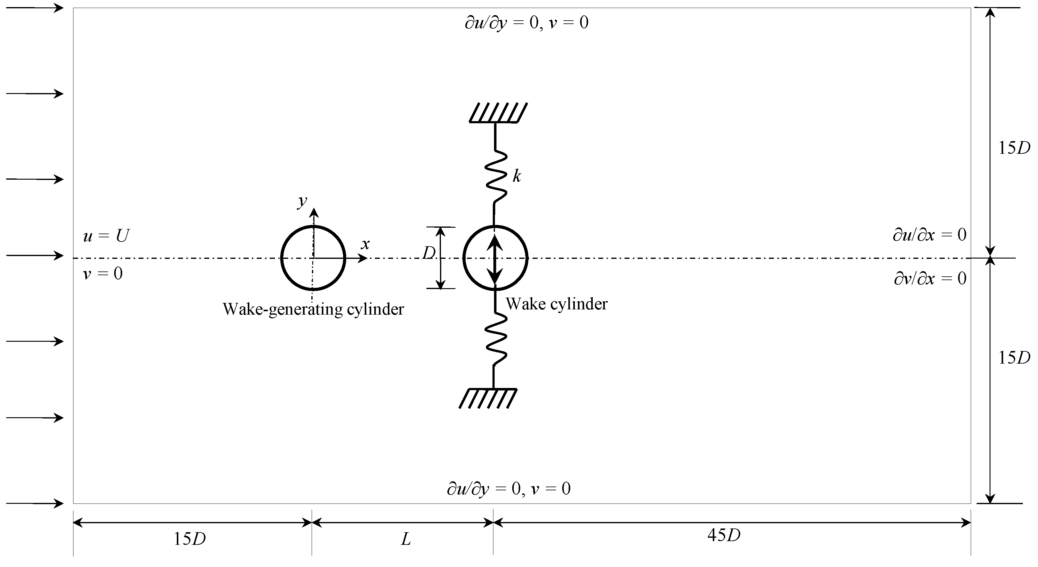
The flow is given in a rectangular computational domain where two circular cylinders are arranged in tandem at the horizontal centerline of the domain (Figure 1). The wake-generating cylinder is fixed, and the wake cylinder is spring-mounted. The latter cylinder is allowed to oscillate in the transverse direction only. The total spring stiffness is k. The Cartesian coordinate system (x–y) has its origin at the center of the wake-generating cylinder. The inlet and outlet boundaries of the computational domain are placed at x = −15 D and L + 45 D, respectively, where L is the distance between the centers of the cylinders, and D is the diameter. The upper and lower boundaries are symmetrically separated by 30 D from each other [17,18]. The corresponding cylinder blockage ratio is 3.3% [19].
2.2. Governing Equations and Numerical Technique
The continuity and Navier–Stokes equations are the governing equations that can be written as:
The parameters in the equations are non-dimensional and have the following expressions.
Here, u and ν are the streamwise and transverse components of the flow velocity, respectively, p is the static pressure, μ is the fluid viscosity, U is the freestream velocity, and t is the time.
The cylinders are surrounded by an O-xy grid system while a rectangular grid system is provided away from the cylinders, as shown in Figure 2. The meshes around the cylinders are given a greater density. We set the first grid level 0.009D away from the cylinder surface, with a mesh expansion ratio of less than 1.1. The simulation uses a dynamic mesh scheme where the ANSYS-Fluent 15 solver is used to move boundaries and/or objects and to adjust the mesh accordingly. The grid box around the cylinder moves with the cylinder displacement. The user-defined function is feed into the solver to estimate the cylinder displacement. At each time step, the domain deformation is handled by the dynamic meshing tool in ANSYS-Fluent 15, and the mesh is updated using the Laplace smoothing method.
The boundary conditions are given as
u* = 0 and v* = 0 at the surfaces of the upstream and downstream cylinders,
u* = 1 and v* = 0 at the inlet,
∂u*/∂y* = 0 and v* = 0 at the lateral sides, and
∂u*/∂x* = 0 and ∂v*/∂x* = 0 at the outlet.
In the governing Equations (1)–(3), p*, u* and v* are the unknown parameters, solved by coupling the governing equations. They are solved for the unsteady and incompressible flow with constant fluid properties. The computations are conducted using the finite volume method. The convective components are discretized using the second-order upwind scheme. The coupling between the velocity and pressure fields is done by the pressure correction-based iterative algorithm SIMPLE (Semi-implicit method for pressure linked equations) proposed by Patankar [20]. We used a first-order implicit formulation for the time discretization.
The governing equation of the cylinder motion in the dimensionless form can be written as:
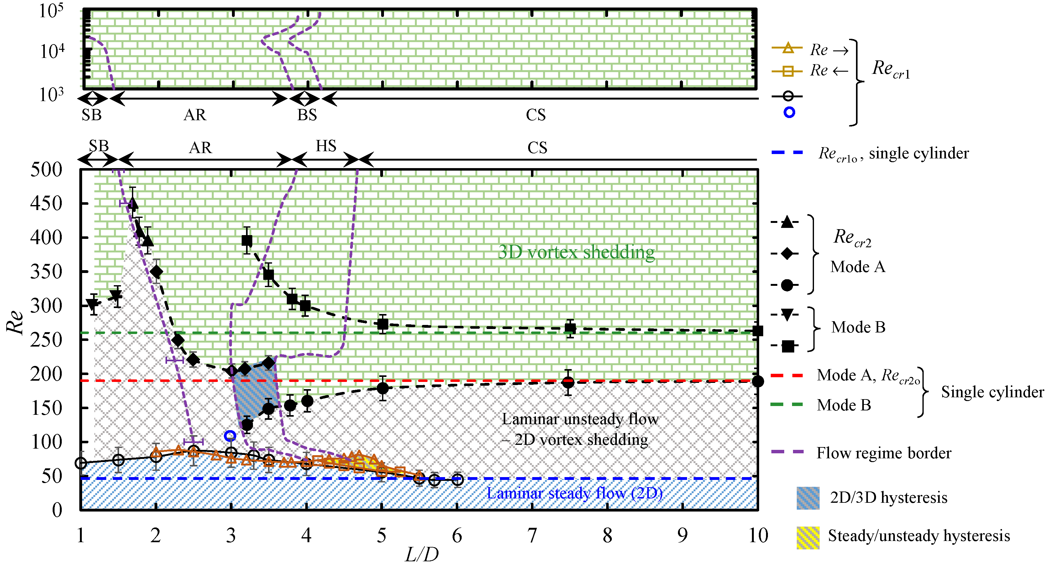
where Y is the cylinder displacement measured from y = 0, is the cylinder velocity, and is the cylinder acceleration. The CLi is the instantaneous lift coefficient of the cylinder. The Fn = fnD/U, where fn is the natural frequency of the cylinder. The m* (=4 m/ρπD2) is the cylinder mass ratio, where m stands for the mass of the cylinder. We solved Equation (4) using the fourth-order Runge-Kutta method for every time step. The Re = 150 for all simulations including validation. The flow around a single cylinder transits from two- to three-dimensional at Re ≈ 190 [21]. When two cylinders are placed in tandem, the transition Re (Recr2) from two-dimensional to three-dimensional flows is delayed for L/D ≤ 3.0, see Figure 3 reproduced from Rastan and Alam [22]. The flow around two tandem cylinders at L/D = 1.5 and 3.0 examined is thus assumed to be two-dimensional.
2.3. Validation
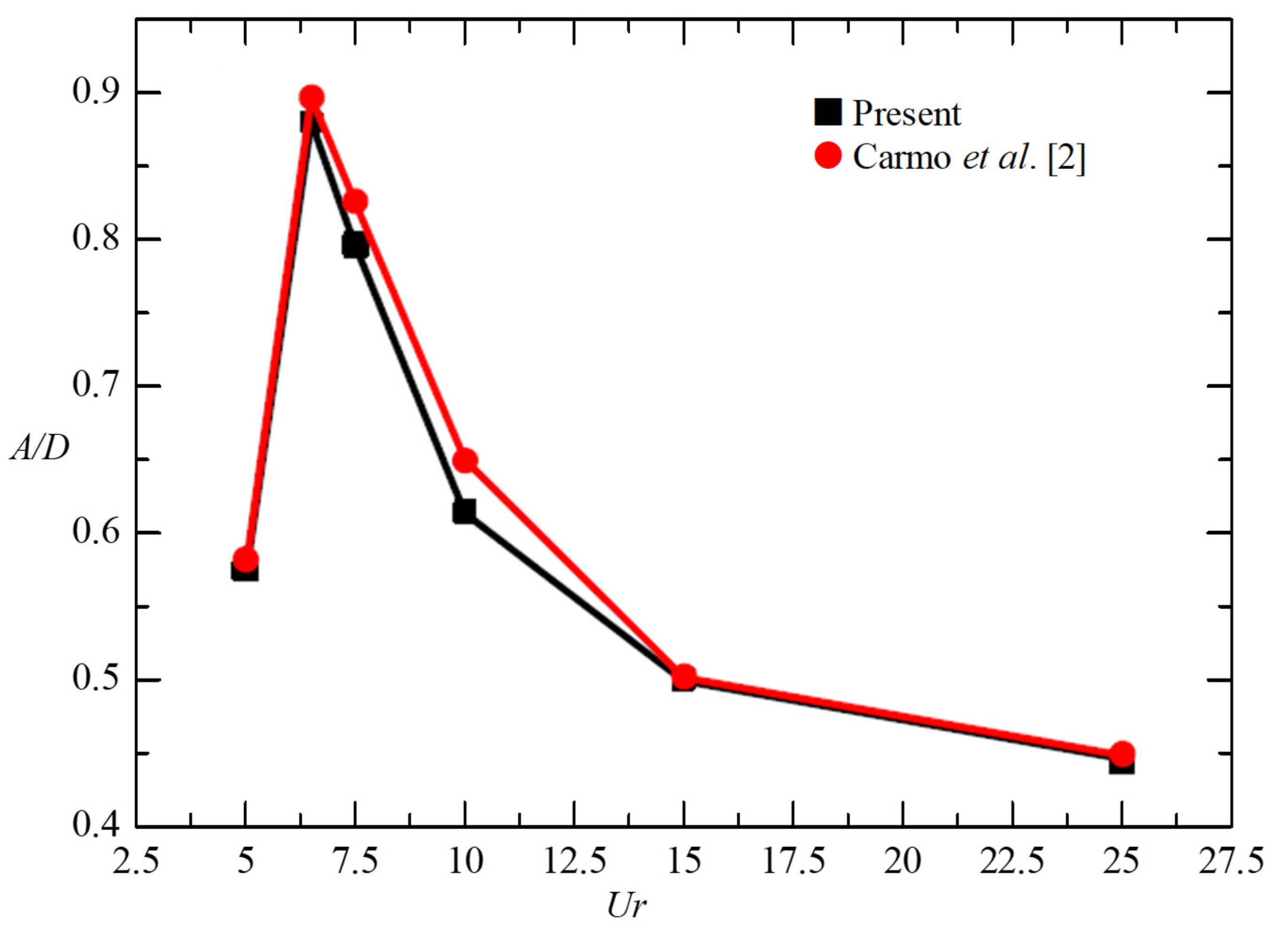
A mesh independence test was conducted based on the mesh system adopted in Zafar and Alam [23] and Abdelhamid et al. [24]. Three different meshes (M1, M2, and M3 consisting of 76,350, 80,050, and 9400 elements, respectively) are tested for a single fixed cylinder at Re = 150. The results of global parameters including time-mean drag coefficient , fluctuating lift coefficient , and Strouhal number St for three different meshes are presented in Table 1 and compared with those in the literature. The results for the three mesh systems are essentially converged as these mesh systems were decided based on the mesh systems in [23,24,25,26]. The maximum deviation in is found to be less than 2.5%. The present results overall show quite good agreement with those from the literature. Mesh M2 system, with the same grid distributions around the two cylinders, was, however, used for the computations of two tandem cylinders when the wake cylinder is free to oscillate, and the results are validated again in Figure 4. To compare our results with the numerical results of Carmo et al. [2], we first simulated vibration responses for m* = 2, ζ = 0.003, and L/D = 3 which are the same geometrical and physical conditions used by Carmo et al. [2]. A comparison between the present and Carmo et al.’s results is made in Figure 4 where the vibration amplitude ratio A/D is presented against Ur. Here, A represents the cylinder vibration amplitude obtained from displacement signal Y. First, root-mean-square (rms) value of Y (Yrms) is obtained, and then A is calculated as . The present results agree well with those by Carmo et al. [2], with a maximum deviation of 5% occurring at Ur = 10.
3. Results and Discussion
3.1. Vibration Response at Small m* and ζ
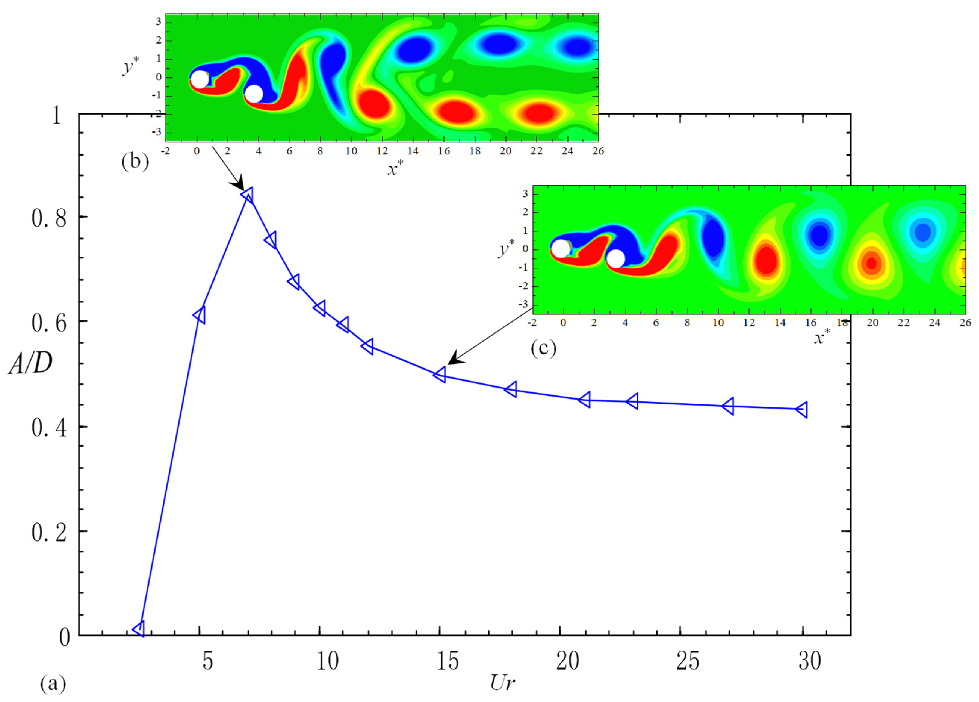
Figure 5 shows the dependence of vibration amplitude ratio A/D on Ur for m* = 2, ζ = 0.005 and L/D = 3.0. The A/D firstly increases with increasing Ur, reaching a peak at Ur = 7 before declining with a further increase in Ur. The decline is rapid for Ur = 7–15 but mild for Ur > 15. The vorticity structures shown in Figure 5b,c illustrate that each of the wakes at Ur = 7 and 15 is characterized by two rows of opposite sign vortices. Yet, the two wakes differ in different aspects. Firstly, the lateral separation between the two vortex rows is wider for Ur = 7 than for Ur = 15. Secondly, the streamwise distance between two consecutive vortices is large for Ur = 15, compared to that for Ur = 7. As the vibration amplitude gently decreases with Ur for Ur > 15 (Figure 5a), there is no galloping. In a water tunnel test, Bokaian and Geoola [1] observed galloping vibration at 1.09 ≤ L/D ≤ 3 in the range of Re = 600–6000 with m* ζ = 0.109. When both cylinders are allowed to vibrate, Kim et al. [12] in a wind tunnel test found the occurrence of galloping vibrations for 1.2 ≤ L/D ≤ 1.6 at Re = 4365–74,200 and m* ζ = 0.64. It suggests that the occurrence of galloping is highly sensitive to L/D, Re, and m* ζ. Interestingly, as seen in Figure 5, the A/D value remains high (A/D > 0.4) even at high Ur (>15). It is worth investigating whether galloping occurs at other m* and ζ values. We will therefore focus on the vibration response at large Ur (>10) only.
3.2. Effect of Damping Ratio on Vibration Amplitude
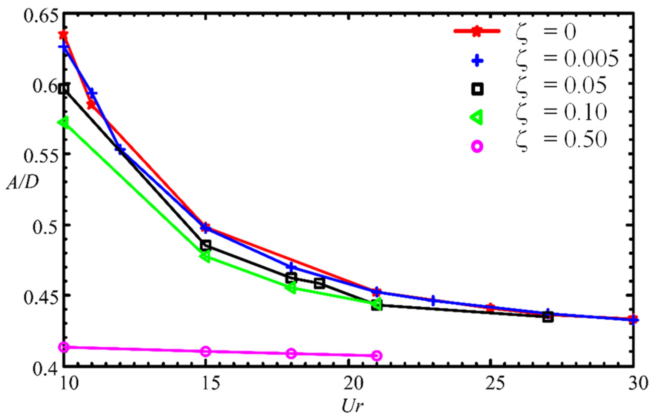
The vibration response is investigated for Ur > 10 when ζ is increased from 0 to 0.5. Figure 6 depicts the effect of ζ (=0–0.5) on A/D for Ur = 10–30 with m* = 2 and L/D = 3. There is no apparent difference in A/D between ζ = 0 and 0.005 while A/D for both ζ values diminishes, particularly at Ur = 10–15, with increasing ζ for ζ > 0.005. The A/D at the largest ζ = 0.5 examined is not very sensitive to Ur. It should be noted that A/D is still larger than 0.4 even at the largest ζ = 0.5 examined. From Figure 6, it is understood that the degree of ζ effect on A/D is not the same at different Ur values. Then, what is the relationship between ζ and A/D at different Ur values? A further question arises, is the ζ effect on A/D is the same at other m* values?
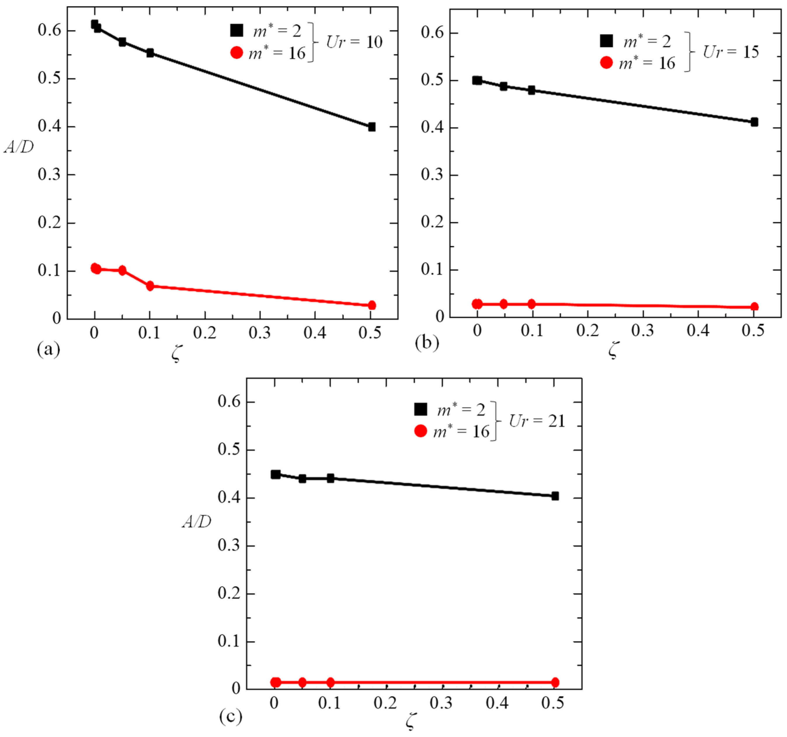
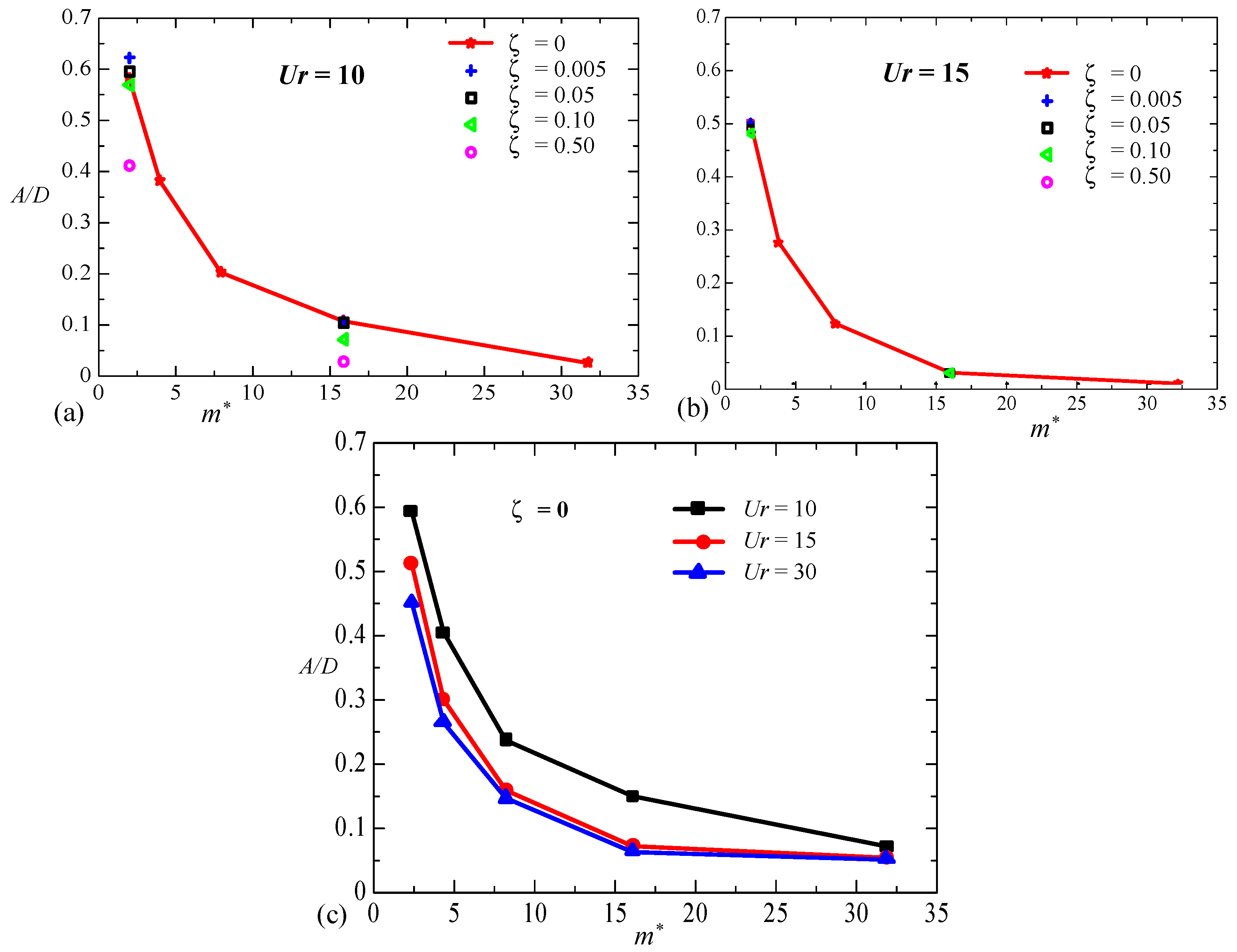
Figure 7 answers the above-mentioned two questions where A/D is presented against ζ for m* = 2 and 16 in the case of Ur = 10, 15 and 21. As seen in the figure, an increase in ζ causes a reduction in A/D for both m* = 2 and 16 with Ur = 10 (Figure 7a). The reduction is, however, large at small m*, the gradient (d(A/D)/dζ) in the range of ζ = 0–0.5 being −0.42 and −0.15 for m* = 2 and 16, respectively. When m* is increased from 2 to 16, dramatic reductions in A/D occur for all ζ values (Figure 7a). Although a similar observation is made for Ur = 15 (Figure 7b), the gradient magnitude is smaller for Ur = 15 than for Ur = 10. The A/D becomes almost insensitive to ζ for Ur = 21. Overall, the effect of ζ on A/D is large at small m* and small Ur. The m* effect on A/D is significant for all ζ values, albeit larger at a smaller ζ. Given that the ζ values of engineering structures appear less than 0.1 and the m* may vary up to the order of 3 [32,33,34,35], it can be said the effect of m* on A/D is much more than that of ζ.
3.3. Effect of Mass Ratio on Vibration Amplitude
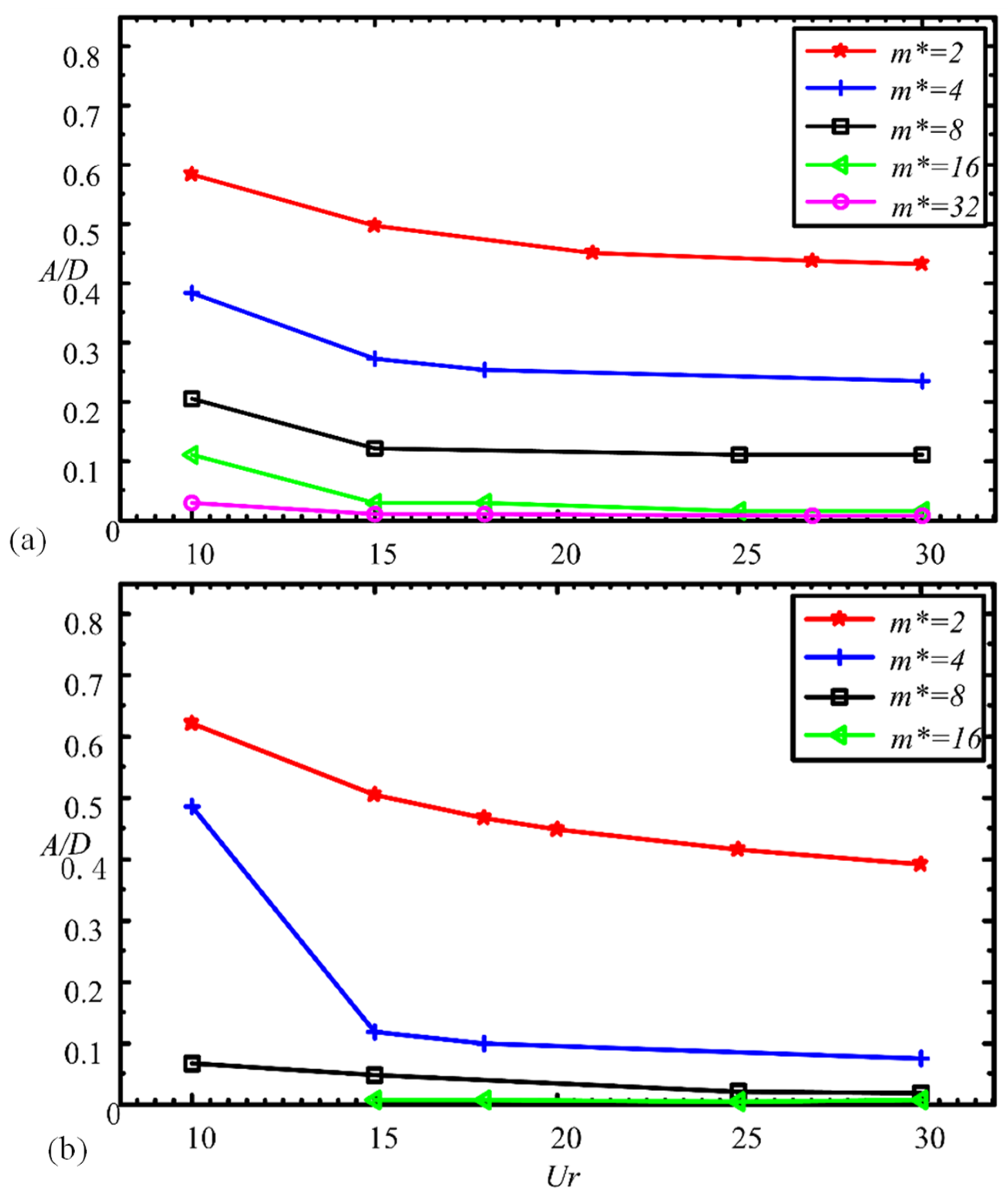
More detail of the effect of m* on A/D is presented in Figure 8 for L/D = 3.0 and 1.5 with ζ = 0. For both L/D values, A/D decreases with increasing m*, the decrease being large at small Ur. Considering the steps of the increase in m*, the decrease in A/D is largest between m* = 2 and 4. When m* is large enough (i.e., m* = 32 and 16 for L/D = 3.0 and 1.5, respectively), A/D becomes very small and almost independent of Ur. There is a large drop in A/D for m* = 4 from Ur = 10 to 15. As seen, A/D is highly sensitive to m* for m* = 2–8. At m* = 4, it seems that A/D at Ur = 10 and Ur ≥ 15 has similar characteristics to that at m* = 2 and 8, respectively. There might be a transition from high- to low-amplitude vibration between Ur = 10 and 15, which requires further investigation.
Figure 9 shows the dependence of A/D on m*, Ur and ζ for L/D = 1.5. At Ur = 10 (Figure 9a), with increasing m*, the A/D exponentially drops between m* = 2 and 16 and gently for m* > 16. The same figure (Figure 9a) further proves that there is an effect of ζ on A/D, the effect being small between ζ = 0 and 0.05 but strong between ζ = 0.05 and 0.5. At Ur = 15 (Figure 9b), again the effect of m* on A/D is very strong for m* = 2–16 and weak for m* > 16. Here, the effect of ζ on A/D is very small. Figure 9c further describes the relationship between A/D, m* and Ur. For all Ur values, A/D exponentially declines with increasing m* up to 16. In addition, A/D drops significantly between Ur = 10 and 15 and mildly between Ur = 15 and 30. It can be generalized that A/D is inversely linked to m*, ζ and Ur.
3.4. Effect of Mass-Damping Ratio on Vibration Amplitude
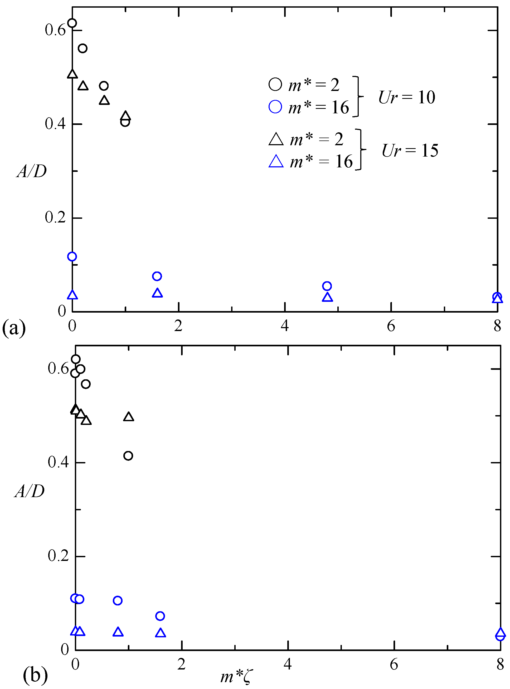
In the previous section, both m* and ζ causes a reduction in A/D. For a single isolated cylinder, mass-damping ratio (m*ζ) has been proven to be another characteristic parameter that has a connection with A/D [36]. The A/D is found to monotonically decrease with increasing m*ζ for a single isolated cylinder [37]. To see the relationship between A/D and m*ζ for the cylinder interacting with the wake, A/D is plotted against m*ζ in Figure 10 for Ur = 10 and 15. For these data, ζ varies from 0 to 0.5 for both m* = 2 and 16 (see the legends in the figure). Interestingly, although A/D decreases with increasing m*ζ for a given m*, the decrease rate is contingent on m*, high at small m*, and vice versa. The A/D data fail to collapse onto a single line against m*ζ, which suggests that m*ζ is not a unique parameter to characterize the vibration for a cylinder interacting with the wake of another cylinder.
3.5. Effects of L/D, m*, and ζ on Wake Structure
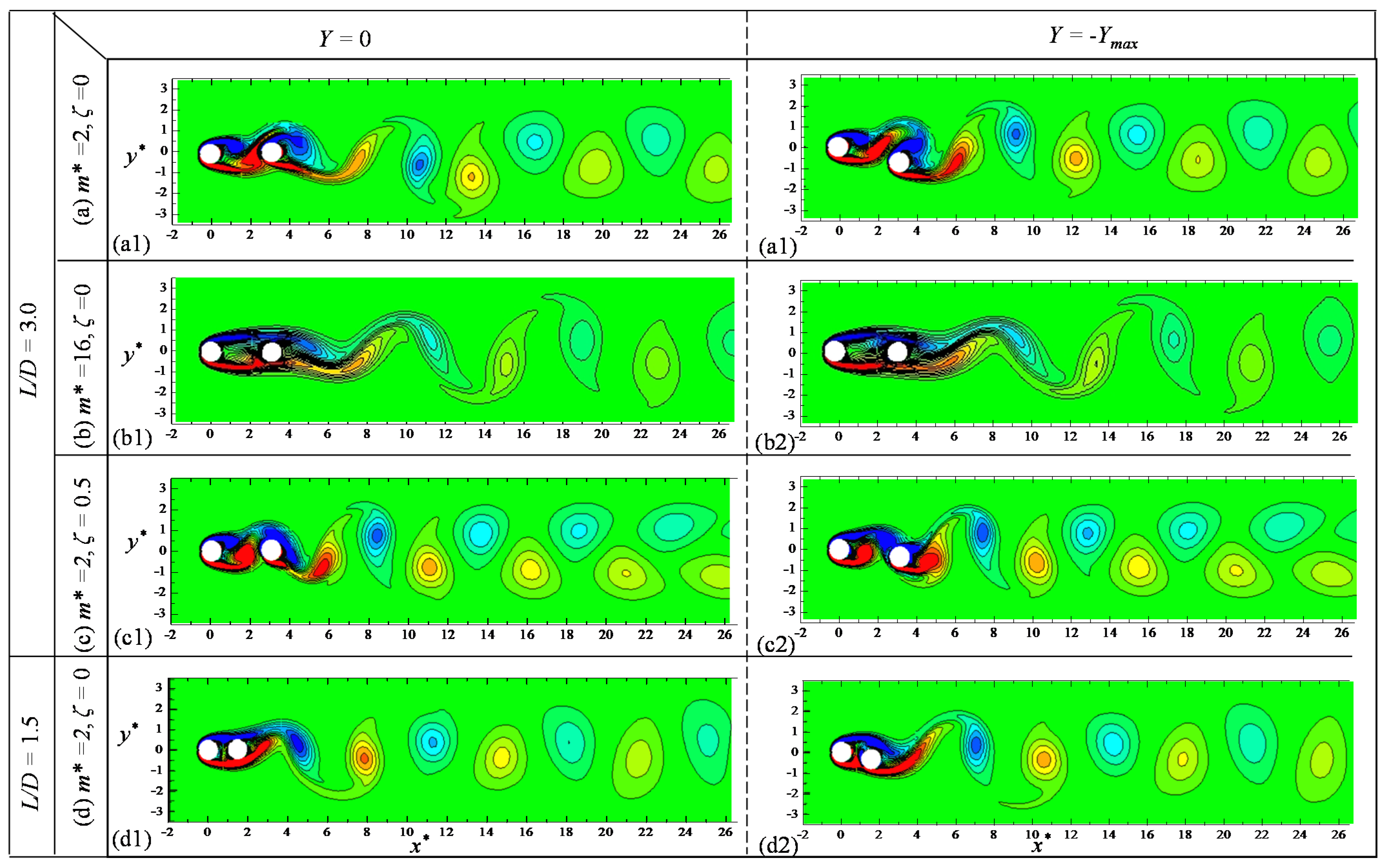
It is worth investigating how the wake structure is modified when L/D, m*, and ζ are changed. Figure 11 shows vorticity structures for L/D = 3.0 and 1.5 for different values of m* and ζ. The first- and second-column snapshots correspond to Y ≈ 0 (i.e., mean position) and Y ≈ Ymax (i.e., maximum displacement), respectively. In the first- and second-row wake structures (Figure 11a,b), the effect of increasing m* from 2 to 16 on the wake structure is displayed. For m* = 2 and ζ = 0 with L/D = 3.0 (Figure 11a), the wake behind the wake cylinder is characterized by 2S mode (i.e., two vortices shed in one oscillation cycle). The shear layers emanating from the wake-generating cylinders roll up into the gap between the cylinders. When the vibrating cylinder is close to the mean position (Y ≈ 0), the vortices from the wake-generating cylinder impinge on the vibrating cylinder. On the other hand, they both pass over the same side of the vibrating cylinder when the vibrating cylinder is at its maximum displacement (Y ≈ Ymax). When the m* is increased to 16 (Figure 11b), the shear layers from the wake-generating cylinder do not roll up in the gap between the cylinders but alternately reattach on the vibrating cylinder. Another remarkable difference in the wake structures between m* = 2 and 16 (Figure 11a,b) is that a greater number of vortices appear in the same downstream distance (x* = 4–26) for m* = 2 than for m* = 16. Given the 2S mode for both cases, it can be argued that the cylinder oscillation frequency reduces when m* is increased from 2 to 16, which is consistent with our intuition.
A comparison of snapshots between the first and third rows gives out the effect of ζ (=0 and 0.5) on the wake structure. The arrangement and structure of vortices in the wake do not differ much between ζ = 0 and 0.5. The vortices in the wake, however, decay more rapidly for ζ = 0 than for ζ = 0.5. The effect of L/D can be understood by comparing the vortex shedding between L/D = 3.0 and 1.5 (Figure 11a,d), both for the same m* and ζ. Although the wake structure is the same for both L/D values, the flow structure around the cylinders is completely different in the two cases. While vortex shedding occurs from both cylinders for L/D = 3.0 (Figure 11a), only the wake cylinder sheds vortices for L/D = 1.5 (Figure 11d). Vortex shedding does not take place in the gap between the cylinders for L/D = 1.5. The alternate reattachment of the shear layer from the wake-generating cylinder sustains the wake cylinder vibration for L/D = 1.5 while alternate impingement and switch of the gap vortices do the same for L/D = 3.0.
4. Conclusions
Flow-induced vibrations of a cylinder interacting with the wake of another cylinder is investigated at Re = 150. The focus is given on the effect of m* (=2–32), ζ (=0–0.5), and m*ζ (=0–8) on A/D at different Ur and L/D values. While investigations at high Re found galloping vibration for the wake cylinder (e.g., [1]), no galloping occurs at this low Re. Following VIV peak, A/D remains high (A/D > 0.4) even at high Ur (>15).
The A/D is more sensitive to m* than to ζ. Both m* and ζ reduce A/D. The effect of ζ on A/D is larger at smaller m*. On the other hand, the m* has a considerable effect on A/D for all ζ values. The effect is, however, strong for m* = 2–16 and relatively weak for m* > 16. Generally, the A/D is inversely linked to m* and ζ.
Although m*ζ is believed to be a unique parameter determining the vibration amplitude for a single isolated cylinder, this is not the case for the cylinder interacting with the wake generated by another. Although A/D decreases with m*ζ, the decrease rate is high at small m*. As such, the A/D data fail to collapse onto a single line against m*ζ, which signifies that m*ζ is not a parameter that uniquely characterizes interaction of a cylinder with the wake of another cylinder.
The shear layers of the wake-generating cylinder do roll up in the gap between the cylinders at m* = 2 for ζ = 0, Ur = 10, and L/D = 3. With the same initial conditions (ζ = 0, Ur = 10, and L/D = 3), when m* is increased to 16, the shear layers do not roll up in the gap but alternately reattach on the vibrating cylinder. Vortices in the wake appear more for m* = 2 than for m* = 16, decaying more rapidly at small ζ. While the wake-generating-cylinder shear layers reattaching alternately on the wake cylinder fuels the vibration of the wake cylinder for L/D = 1.5, the gap-vortex impingement and switch do the same for L/D = 3.0. The results are useful to riser designers to understand the role of m* and ζ in flow-induced vibrations.
Funding
This research was funded by the Khalifa University of Science and Technology through Grants CIRA-2020-057.
Data Availability Statement
The data that support the findings of this study are available within the article.
Acknowledgments
The author also greatly acknowledges the contribution of Liu Haifeng to simulation.
Conflicts of Interest
The author declares no conflict of interest.
References
- Bokaian, A.; Geoola, F. Wake-induced galloping of two interfering circular cylinders. J. Fluid Mech. 1984, 146, 383–415. [Google Scholar] [CrossRef]
- Carmo, B.; Sherwin, S.; Bearman, P.; Willden, R. Flow-induced vibration of a circular cylinder subjected to wake interference at low Reynolds number. J. Fluids Struct. 2011, 27, 503–522. [Google Scholar] [CrossRef]
- Hover, F.; Triantafyllou, M. Galloping response of a cylinder with upstream wake interference. J. Fluids Struct. 2001, 15, 503–512. [Google Scholar] [CrossRef]
- Assi, G.R.S.; Bearman, P.W.; Meneghini, J.R. On the wake-induced vibration of tandem circular cylinders: The vortex interaction excitation mechanism. J. Fluid Mech. 2010, 661, 365–401. [Google Scholar] [CrossRef]
- Assi, G.R.D.S.; Bearman, P.W.; Carmo, B.; Meneghini, J.R.; Sherwin, S.; Willden, R.H.J. The role of wake stiffness on the wake-induced vibration of the downstream cylinder of a tandem pair. J. Fluid Mech. 2013, 718, 210–245. [Google Scholar] [CrossRef] [Green Version]
- Qin, B.; Alam, M.; Zhou, Y. Two tandem cylinders of different diameters in cross-flow: Flow-induced vibration. J. Fluid Mech. 2017, 829, 621–658. [Google Scholar] [CrossRef]
- Qin, B.; Alam, M.M.; Zhou, Y. Free vibrations of two tandem elastically mounted cylinders in cross-flow. J. Fluid Mech. 2019, 861, 349–381. [Google Scholar] [CrossRef]
- Assi, G.R.S.; Meneghini, J.R.; Aranha, J.; Bearman, P.; Casaprima, E. Experimental investigation of flow-induced vibration interference between two circular cylinders. J. Fluids Struct. 2006, 22, 819–827. [Google Scholar] [CrossRef]
- Korkischko, I.; Meneghini, J.R. Experimental investigation of flow-induced vibration on isolated and tandem circular cylinders fitted with strakes. J. Fluids Struct. 2010, 26, 611–625. [Google Scholar] [CrossRef]
- Qin, B.; Alam, M.; Ji, C.; Liu, Y.; Xu, S. Flow-induced vibrations of two cylinders of different natural frequencies. Ocean Eng. 2018, 155, 189–200. [Google Scholar] [CrossRef]
- Zdravkovich, M. Flow induced oscillations of two interfering circular cylinders. J. Sound Vib. 1985, 101, 511–521. [Google Scholar] [CrossRef]
- Kim, S.; Alam, M.; Sakamoto, H.; Zhou, Y. Flow-induced vibrations of two circular cylinders in tandem arrangement. Part 1: Characteristics of vibration. J. Wind. Eng. Ind. Aerodyn. 2009, 97, 304–311. [Google Scholar] [CrossRef]
- Huera-Huarte, F.; Bearman, P. Vortex and wake-induced vibrations of a tandem arrangement of two flexible circular cylinders with near wake interference. J. Fluids Struct. 2011, 27, 193–211. [Google Scholar] [CrossRef]
- Papaioannou, G.; Yue, D.; Triantafyllou, M.; Karniadakis, G. On the effect of spacing on the vortex-induced vibrations of two tandem cylinders. J. Fluids Struct. 2008, 24, 833–854. [Google Scholar] [CrossRef]
- Borazjani, I.; Sotiropoulos, F. Vortex-induced vibrations of two cylinders in tandem arrangement in the proximity–wake interference region. J. Fluid Mech. 2009, 621, 321–364. [Google Scholar] [CrossRef] [PubMed] [Green Version]
- Prasanth, T.; Mittal, S. Flow-induced oscillation of two circular cylinders in tandem arrangement at low Re. J. Fluids Struct. 2009, 25, 1029–1048. [Google Scholar] [CrossRef]
- Zheng, Q.; Alam, M. Intrinsic features of flow past three square prisms in side-by-side arrangement. J. Fluid Mech. 2017, 826, 996–1033. [Google Scholar] [CrossRef]
- Zheng, Q.; Alam, M. Evolution of the wake of three inline square prisms. Phys. Rev. Fluids 2019, 4, 104701. [Google Scholar] [CrossRef]
- Bhatt, R.; Alam, M. Vibrations of a square cylinder submerged in a wake. J. Fluid Mech. 2018, 853, 301–332. [Google Scholar] [CrossRef]
- Patankar, S.V. Numerical Heat Transfer and Fluid Flow; CRC Press: Boca Raton, FL, USA, 1980; ISBN 9781315275130. [Google Scholar]
- Barkley, D.; Henderson, R. Three-dimensional Floquet stability analysis of the wake of a circular cylinder. J. Fluid Mech. 1996, 322, 215–241. [Google Scholar] [CrossRef] [Green Version]
- Rastan, M.R.; Alam, M.M. Transition of wake flows past two circular or square cylinders in tandem. Phys. Fluids 2021, 33, 081705. [Google Scholar] [CrossRef]
- Zafar, F.; Alam, M.M. Flow structure and heat transfer from cylinders modified from square to circular. Phys. Fluids 2019, 31, 083604. [Google Scholar] [CrossRef]
- Abdelhamid, T.; Alam, M.M.; Islam, M. Heat transfer and flow around cylinder: Effect of corner radius and Reynolds number. Int. J. Heat Mass Transf. 2021, 171, 121105. [Google Scholar] [CrossRef]
- Alam, M.; Abdelhamid, T.; Sohankar, A. Effect of cylinder corner radius and attack angle on heat transfer and flow topology. Int. J. Mech. Sci. 2020, 175, 105566. [Google Scholar] [CrossRef]
- Zafar, F.; Alam, M. A low Reynolds number flow and heat transfer topology of a cylinder in a wake. Phys. Fluids 2018, 30, 083603. [Google Scholar] [CrossRef]
- Sucker, D.; Brauer, H. Fluiddynamik bei der angestromten Zilindern. Warme Stoffubertrag. 1975, 8, 149. [Google Scholar] [CrossRef]
- Norberg, C. Flow around a circular cylinder: Aspects of fluctuating lift. J. Fluids Struct. 2001, 15, 459–469. [Google Scholar] [CrossRef]
- Silva, A.L.E.; Silveira-Neto, A.; Damasceno, J. Numerical simulation of two-dimensional flows over a circular cylinder using the immersed boundary method. J. Comput. Phys. 2003, 189, 351–370. [Google Scholar] [CrossRef]
- Posdziech, O.; Grundmann, R. A systematic approach to the numerical calculation of fundamental quantities of the two-dimensional flow over a circular cylinder. J. Fluids Struct. 2007, 23, 479–499. [Google Scholar] [CrossRef]
- Qu, L.; Norberg, C.; Davidson, L.; Peng, S.-H.; Wang, F. Quantitative numerical analysis of flow past a circular cylinder at Reynolds number between 50 and 200. J. Fluids Struct. 2013, 39, 347–370. [Google Scholar] [CrossRef] [Green Version]
- Dong, R.G. Effective Mass and Damping of Submerged Structures; UCRL-52342; Lawrence Livermore Laboratory, California University: Oakland, CA, USA, 1978. [Google Scholar]
- Tabatabai, H.; Mehrabi, A. Design of Mechanical Viscous Dampers for Stay Cables. J. Bridg. Eng. 2000, 5, 114–123. [Google Scholar] [CrossRef]
- Alam, M.; Kim, S. Free vibration of two identical circular cylinders in staggered arrangement. Fluid Dyn. Res. 2009, 41, 17. [Google Scholar] [CrossRef]
- Alam, M.; Meyer, J. Global aerodynamic instability of twin cylinders in cross flow. J. Fluids Struct. 2013, 41, 135–145. [Google Scholar] [CrossRef] [Green Version]
- Khalak, A.; Williamson, C. Dynamics of a hydroelastic cylinder with very low mass and damping. J. Fluids Struct. 1996, 10, 455–472. [Google Scholar] [CrossRef]
- Williamson, C.; Govardhan, R. Vortex-induced vibrations. Annu. Rev. Fluid Mech. 2004, 36, 413–455. [Google Scholar] [CrossRef] [Green Version]
Figure 1.
A schematic of cylinder configuration and computational domain.

Figure 2.
(a) Grid system in the computational domain and (b) close-up view of grids around the cylinders. L/D = 1.5.
Figure 2.
(a) Grid system in the computational domain and (b) close-up view of grids around the cylinders. L/D = 1.5.

Figure 3.
Marginal flow map (colored background) and flow regimes bordered by purple lines for two tandem circular cylinders. SB, slender/extended-body flow; AR, alternate reattachment flow; HS, hysteresis zone; BS, bi-stable flow; CS, co-shedding flow. Reproduced from Rastan and Alam [22]. For the definitions of the legends, please refer to Rastan and Alam [22]. Recr1 represents the flow transition from steady to two-dimensional unsteady while Recr2 indicates the flow transition from two-dimensional unsteady to three-dimensional unsteady.

Figure 4.
Validation of wake-cylinder vibration amplitude A/D plotted against reduced velocity Ur. L/D = 3, m* = 2, ζ = 0.003, and Re = 150.
Figure 4.
Validation of wake-cylinder vibration amplitude A/D plotted against reduced velocity Ur. L/D = 3, m* = 2, ζ = 0.003, and Re = 150.

Figure 5.
(a) Variation in vibration amplitude A/D with reduced velocity Ur. Vorticity structures for (b) Ur = 7 and (c) Ur = 15. L/D = 3, m* = 2, and ζ = 0.005.
Figure 5.
(a) Variation in vibration amplitude A/D with reduced velocity Ur. Vorticity structures for (b) Ur = 7 and (c) Ur = 15. L/D = 3, m* = 2, and ζ = 0.005.

Figure 6.
Effect of damping ratio ζ on vibration amplitude A/D. L/D = 3 and m* = 2.

Figure 7.
Effect of damping ratio ζ on vibration amplitude A/D at different m* and Ur. (a) Ur = 10, (b) Ur = 15, and (c) Ur = 21. L/D = 3.
Figure 7.
Effect of damping ratio ζ on vibration amplitude A/D at different m* and Ur. (a) Ur = 10, (b) Ur = 15, and (c) Ur = 21. L/D = 3.

Figure 8.
Effect of mass ratio m* on vibration amplitude A/D. (a) L/D = 3.0 and (b) L/D = 1.5. ζ = 0.
Figure 8.
Effect of mass ratio m* on vibration amplitude A/D. (a) L/D = 3.0 and (b) L/D = 1.5. ζ = 0.

Figure 9.
Effect of mass ratio m* on vibration amplitude A/D at different ζ and Ur values when (a) Ur = 10, (b) Ur = 10 and (c) ζ = 0. L/D = 1.5.
Figure 9.
Effect of mass ratio m* on vibration amplitude A/D at different ζ and Ur values when (a) Ur = 10, (b) Ur = 10 and (c) ζ = 0. L/D = 1.5.

Figure 10.
A/D vs. mass-damping ratio (m*ζ). (a) L/D = 3.0, and (b) L/D = 1.5.

Figure 11.
Vorticity contours for (a) m* = 2, ζ = 0, L/D = 3.0; (b) m* = 16, ζ = 0, L/D = 3.0; (c) m* = 2, ζ = 0.5, L/D = 3.0; and (d) m* = 2, ζ = 0, L/D = 1.5. Ur = 10.
Figure 11.
Vorticity contours for (a) m* = 2, ζ = 0, L/D = 3.0; (b) m* = 16, ζ = 0, L/D = 3.0; (c) m* = 2, ζ = 0.5, L/D = 3.0; and (d) m* = 2, ζ = 0, L/D = 1.5. Ur = 10.


Table 1.
Mesh independence test results for a single fixed cylinder at Re = 150.
| Mesh | Elements | St | |||
|---|---|---|---|---|---|
| Present | M1 | 76,350 | 1.3487 | 0.3529 | 0.1850 |
| M2 | 80,050 | 1.3495 | 0.3530 | 0.1851 | |
| M3 | 94,400 | 1.3499 | 0.3532 | 0.1851 | |
| Sucker and Brauer [27] | 1.36 | ||||
| Norberg [28] | -- | 0.3555 | 0.1830 | ||
| Silva et al. [29] | 1.37 | -- | -- | ||
| Posdziech and Grundmann [30] | 1.3224 | -- | 0.1841 | ||
| Qu et al. [31] | 1.3152 | 0.3560 | 0.1845 | ||
| Abdelhamid et al. [24] | -- | 0.3537 | 0.1828 |
Publisher’s Note: MDPI stays neutral with regard to jurisdictional claims in published maps and institutional affiliations. |
© 2021 by the author. Licensee MDPI, Basel, Switzerland. This article is an open access article distributed under the terms and conditions of the Creative Commons Attribution (CC BY) license (https://creativecommons.org/licenses/by/4.0/).
Share and Cite
MDPI and ACS Style
Alam, M.M. Effects of Mass and Damping on Flow-Induced Vibration of a Cylinder Interacting with the Wake of Another Cylinder at High Reduced Velocities. Energies 2021, 14, 5148. https://doi.org/10.3390/en14165148
AMA Style
Alam MM. Effects of Mass and Damping on Flow-Induced Vibration of a Cylinder Interacting with the Wake of Another Cylinder at High Reduced Velocities. Energies. 2021; 14(16):5148. https://doi.org/10.3390/en14165148
Chicago/Turabian StyleAlam, Md. Mahbub. 2021. "Effects of Mass and Damping on Flow-Induced Vibration of a Cylinder Interacting with the Wake of Another Cylinder at High Reduced Velocities" Energies 14, no. 16: 5148. https://doi.org/10.3390/en14165148
Note that from the first issue of 2016, this journal uses article numbers instead of page numbers. See further details here.