1. Introduction
BriXS (Bright and compact X-ray Source) [
1] is a twin Compton X-ray source based on superconductive cavities technology for the electron beam with energy recirculation and on a laser system in Fabry-Pérot cavity at a repetition rate of 100 MHz, producing 20–180 keV radiation.
It has been conceived as the first acceleration stage of the X-ray FEL MariX [
2]. MariX is an X-rays FEL based on the innovative design of a two-pass two-way superconducting linear electron accelerator, equipped with an arc compressor to be operated in CW mode at 1 MHz.
The double Compton X-ray sources will operate at a very high repetition rate of 100 MHz, with 200 pC electron bunches, which means a very high average current of 20 mA.
These Compton sources are designed to operate with an electron energy range of 30–100 MeV, which for a 20 mA of current means 2 MW. Such a high beam power cannot be dumped without deceleration, and together with the CW (Continuous Wave) regime, it justifies foreseeing an ERL (Energy Recovery Linac) machine, like in the CBETA ERL project [
3].
The Compton source BriXs will serve a multitude of users in many fields of science and its scientific case is described in detail in Reference [
1].
The focus on enabled applications by such an energy range and brilliance is on medical oriented research/investigations, mainly in the radio-diagnostics and radiotherapy fields [
4], exploiting the unique features of monochromatic X-rays, as well as in micro-biological studies and within this, mainstream, material studies, crystallography and museology for cultural heritage investigations. In this paper, the layout and the typical parameters of the BriXS X-ray source will be discussed.
2. Machine Layout
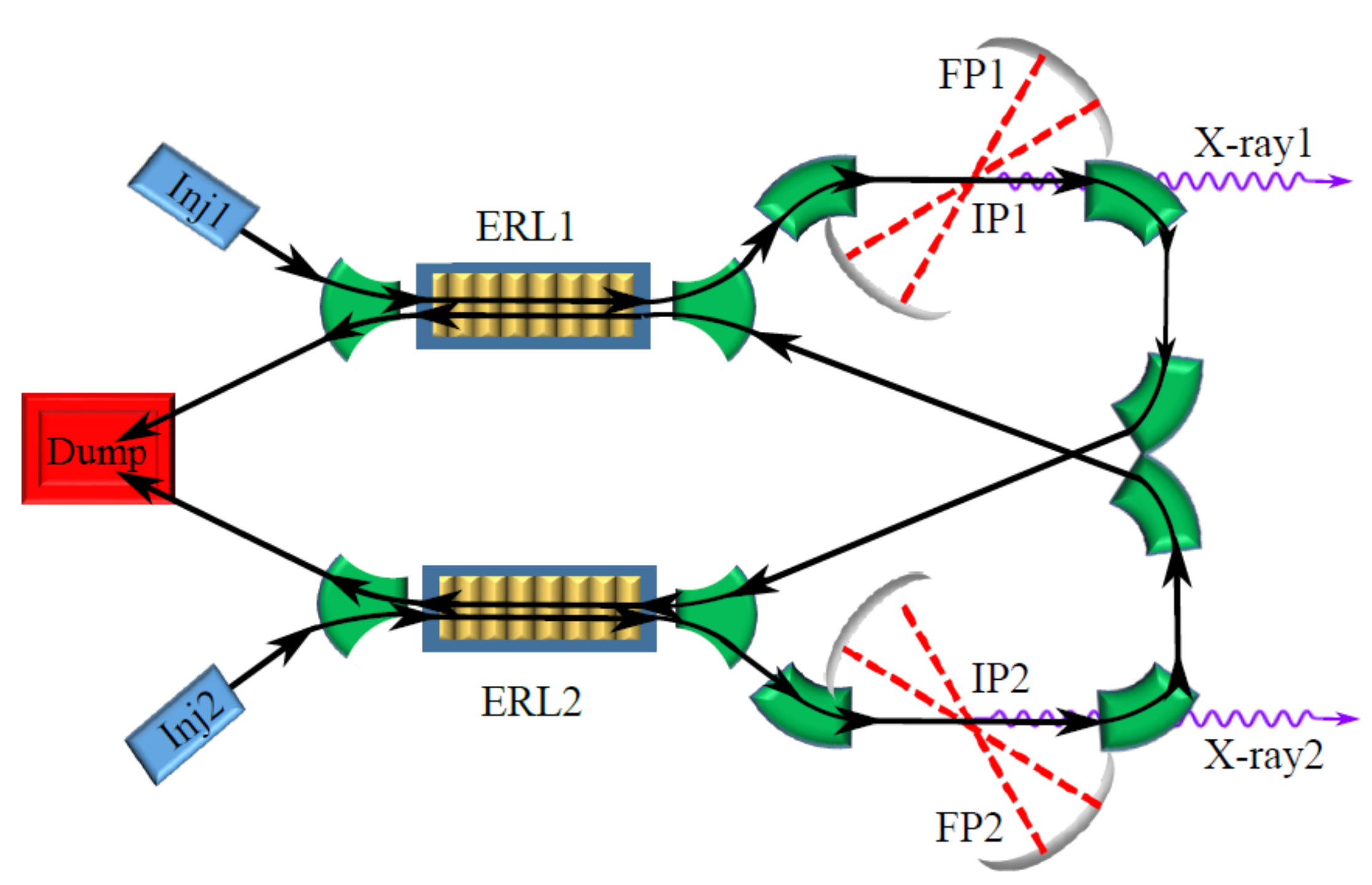
The BriXS layout, shown in
Figure 1, consists of two symmetric beam lines fed by two independent photoinjectors, where two equal and coupled Energy Recovery Linacs (ERL) accelerate the electron beams. Electron trains are extracted from the photo-cathodes Inj1 and Inj2 at the left side of
Figure 1. The two ERLs (named ERL1 and ERL2 in the Figure) accelerate and decelerate the electron trains in an unconventional push-and-pull scheme. Bunches from Guns and travelling right away in the Figure are accelerated, those coming back from the interaction points (IPs) are decelerated during the energy recovery phase and brought simultaneously to a single beam-dump. Each Linac is therefore traversed by two counter-propagating trains of electron beams, both gaining and yielding energy. This push-and-pull coupled scheme permits the concurrent driving of two Compton X-ray sources with the same degrees of freedom—in terms of energy and electron beam quality—as a Linac driven source, with the advantage that the coupled ERLs scheme, fed by two independent RF systems, is more stable. Due to the superconducting technology of the Linacs, the infrastructure works at a repetition rate of 100 MHz, corresponding to average currents up to 20 mA. CW electron Guns, capable of producing such an average beam current, are not yet state of the art. Some of the most promising photo cathode Guns [
5] such as the Cornell DC Gun [
6] and the RF CW Apex Gun [
7] have been therefore compared by simulations. Partial modifications of the beam lines to host additional Compton interaction points are under study. BriXs should be considered a single folded ERL running two beams. This scheme is more compact than two independent ERLs, with the necessity of fewer magnetic elements and, therefore, a minor cost. An important advantage is that the present scheme provides two knobs for adjusting the phases at the entrance of the linacs in the recovery stage, thus circumventing the necessity of additional matching lines for running one single ERL at different energies.
3. Injector
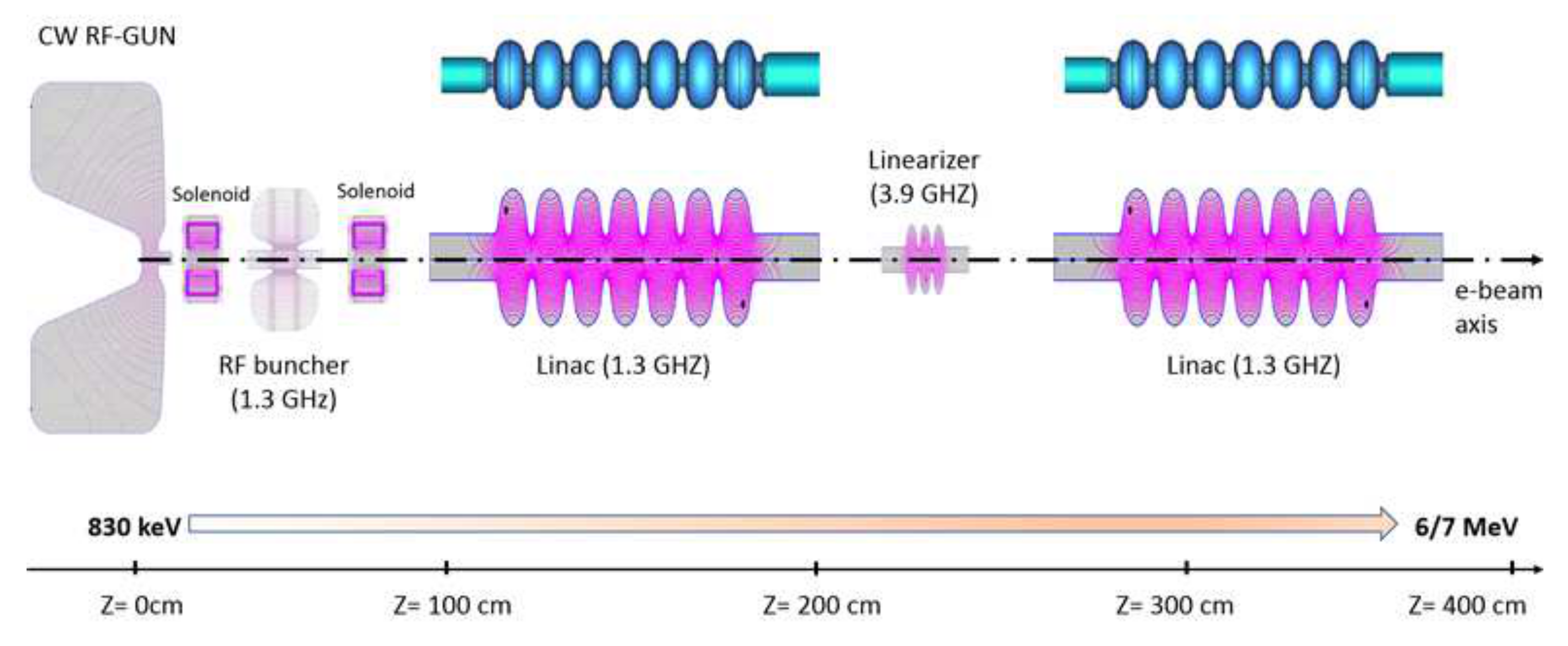
Two twin injectors are present in BriXS. The injector layout of the BriXS/MariX common acceleration beam-line, as sketched in
Figure 2, is composed of the following accelerating and focusing elements: 1. The CW RF Gun; 2. Two focusing solenoids; 3. One RF buncher; 4. Two linear accelerators (linacs); 5. One RF linearizing RF cavity. Being two identical beamlines, we show and discuss only one from here on, for simplicity. The RF power source for each component of the BriXS injector operates in Continuous-Wave (CW), since the high repetition rate (100 MHz) electron beam reaches an average power of 120 kW at the exit, that is, energy up to 6 MeV and an average current of 20 mA. Therefore, the choice of the RF system is based on the maximum average RF power that can be handled by the RF devices. The CW RF-Gun and the RF Buncher are based on normal conducting (NC) technology (copper structures), since the RF power dissipated inside the cavities, required to accelerate and to bunch the electron beam with an energy of about 800 keV at the beginning, can still be handled by using standard water-cooling systems. As a matter of fact, the APEX CW-RF Gun has already shown operation at about 87 kW of average dissipated RF power with the possibility of operating up to 100 kW. As for the two linacs and the RF linearizer, where the high rep-rate beam is accelerated up to at least 6 MeV, we have decided to use superconducting (SC) technology, since standard copper structures are not able to dissipate the high average RF power that would be required. Indeed, the cavity wall power consumption inside an SC structure is lower than an NC one by a factor of
–
. The RF power required by the injector elements represents the major part of the RF power needed for the whole MariX machine. The main reason is the fact that the injector is a one-way acceleration beamline and therefore no energy recovery scheme is employed.
4. Accelerator Section
The requirement for a CW beam structure imposes the choice of the Superconducting technology for the accelerating section, in order to save on capital and operational costs because we want to operate at an accelerating gradient of at least 15 MV/m. This technology has been developed over the past thirty years and has now reached a mature status. The latest most important high repetition rate or CW accelerator facilities (E-XFEL, LCLS-II, ESS, etc.) are now based on this consolidated technology.
The operation of the BriXS accelerator system requires a 100 MeV beam maximum energy at the entrance of the beam line leading to the ICS photon machine. The BriXS beam is CW with a 20 mA current (200 pC at 100 MHz) for each of the branches of the push-pull layout that allow operation of this machine in energy recovery mode.
To provide the required 100 MeV energy boost, we need to consider two important aspects for the selection of the accelerating structure, namely the requirement for RF operation and the effect of the induced High Order Modes on the beam quality. The choice of the BriXS accelerating structure is determined by the above considerations and by the performance already achieved in structures used in installations similar to BriXS. We have evaluated, for this case, two experimentally tested different cavity/module designs:
ERL(KEK), 100 mA current target still to be demonstrated. The based accelerating unit is a cryomodule with two 9-cells cavity design to suppress HOM-BBU up to the nominal current (theoretical limit is 200 mA). It has demonstrated an up to 1 mA CW operation with a % energy recovery and providing a 15 MV/m accelerating gradient. The TESLA-geometry cavity has been modified to accommodate two HOM absorbers able to dissipate up to 150 W. These cavities are operated at 2.0 K.
CBETA (Cornell), multi-pass ERL demonstrator, linac module tested, Design Report. Each module consists of six 7-cell cavities, designed to operate in CW mode at 16 MV/m with a HOM-BBU limit at 100 mA. Specifically designed HOM absorbers installed on both sides are able to handle up to 400 W of dissipated power. These absorbers are isolated from the cavity and they are eventually cooled with liquid nitrogen. The module has been successfully tested and has reached the designed performances. The cryogenic operation temperature for this project is 1.8 K.
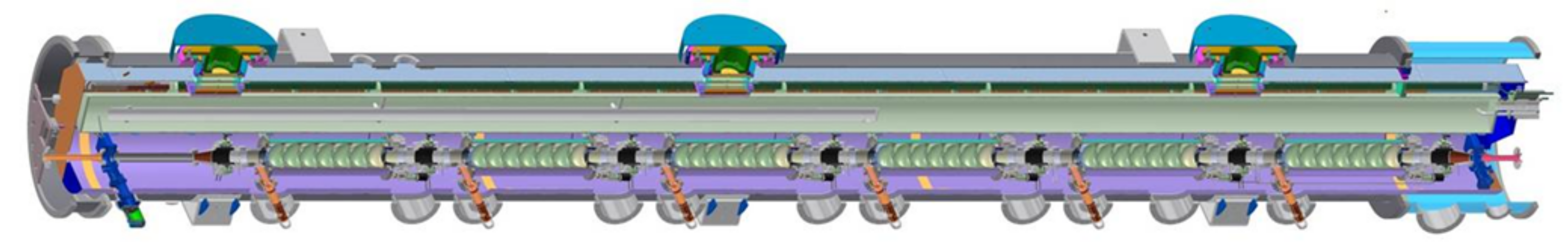
In order to contain the overall module footprint, a solution adopting a single cryomodule hosting the required number of cavities is preferable. This would suggest exploring the opportunities offered by the six-cavities CBETA cryomodule given its demonstrated performance. However, with a 0.81 m single cavity active length, the CBETA cryomodule would yield a 77.8 MeV energy gain when operated at 16 MV/m accelerating gradient. An eight 7-cells cavities geometry CBETA cryomodule appears to be needed to fulfill the energy gain requirements for BriXS. It is clear that, while the CBETA cryomodule remains a reference design (see
Figure 3), dedicated developments are needed for the current project.
Dealing with the cryogenics losses, we need to include the dynamic losses as well as the HOM power. The cryogenic dynamic losses per single cavity, based on the previous parameter set, are expected to be 9.3 W. For the HOM power, in the non-resonant monopole case, the CBETA cavity has a longitudinal loss factor of 14.7 V/pC [
3]. Based on this parameter, the estimated loss power is 117 W per cavity. This value can be reasonably handled by a CBETA-like solution for the HOM absorber made of SiC material and with a cooling jacket held at 80 K.
It is then clear that, if we opt to start from a proofed and operating cavity and cryomodule design, the CBETA layout guarantees these points and allows a smaller total length with respect to a solution like cERL. It is worth noting that modifications of the original CBETA design are necessary to reach the requested 100 MeV energy gain by implementing an 8 cavities per module structure. On the cavity side, we should keep in mind that the
unloaded quality factor is achieved by operating the cavity at 1.8 K, while we are now aiming at operating BriXS at 2.0 K. While the CBETA cavity has shown to reach our specification also at 2.0 K, we are now considering introducing an Electro Polishing process in the cavity treatment procedure (well established in the XFEL production). This will help BriXS achieve higher
values and will give us more confidence in reaching the design unloaded
Q value. In
Table 1, we summarize the BriXS requirements and the accelerating section design parameters. The electron beam at the Linac exit parameters are shown in the
Table 2.
5. Electron Beam Lines
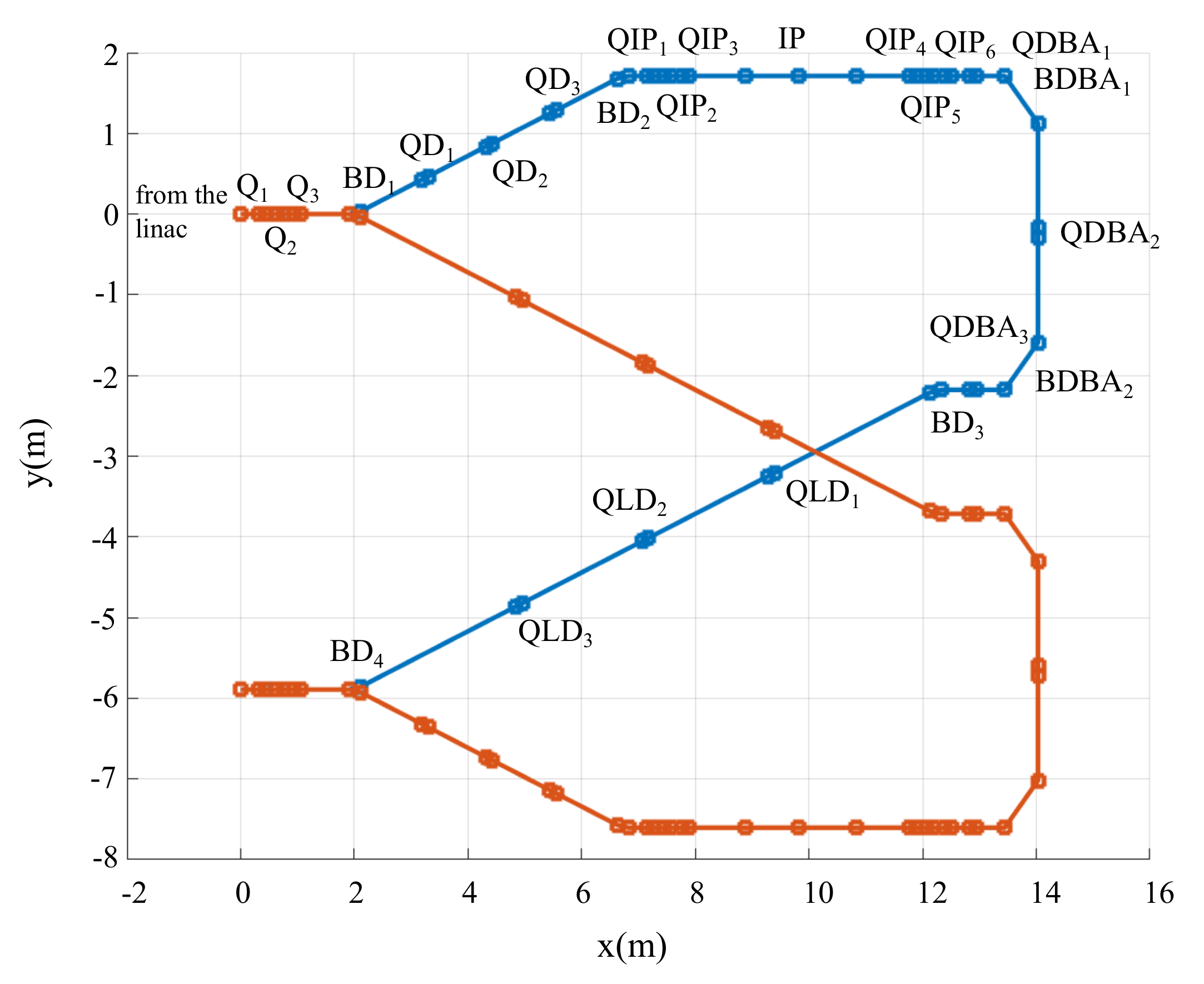
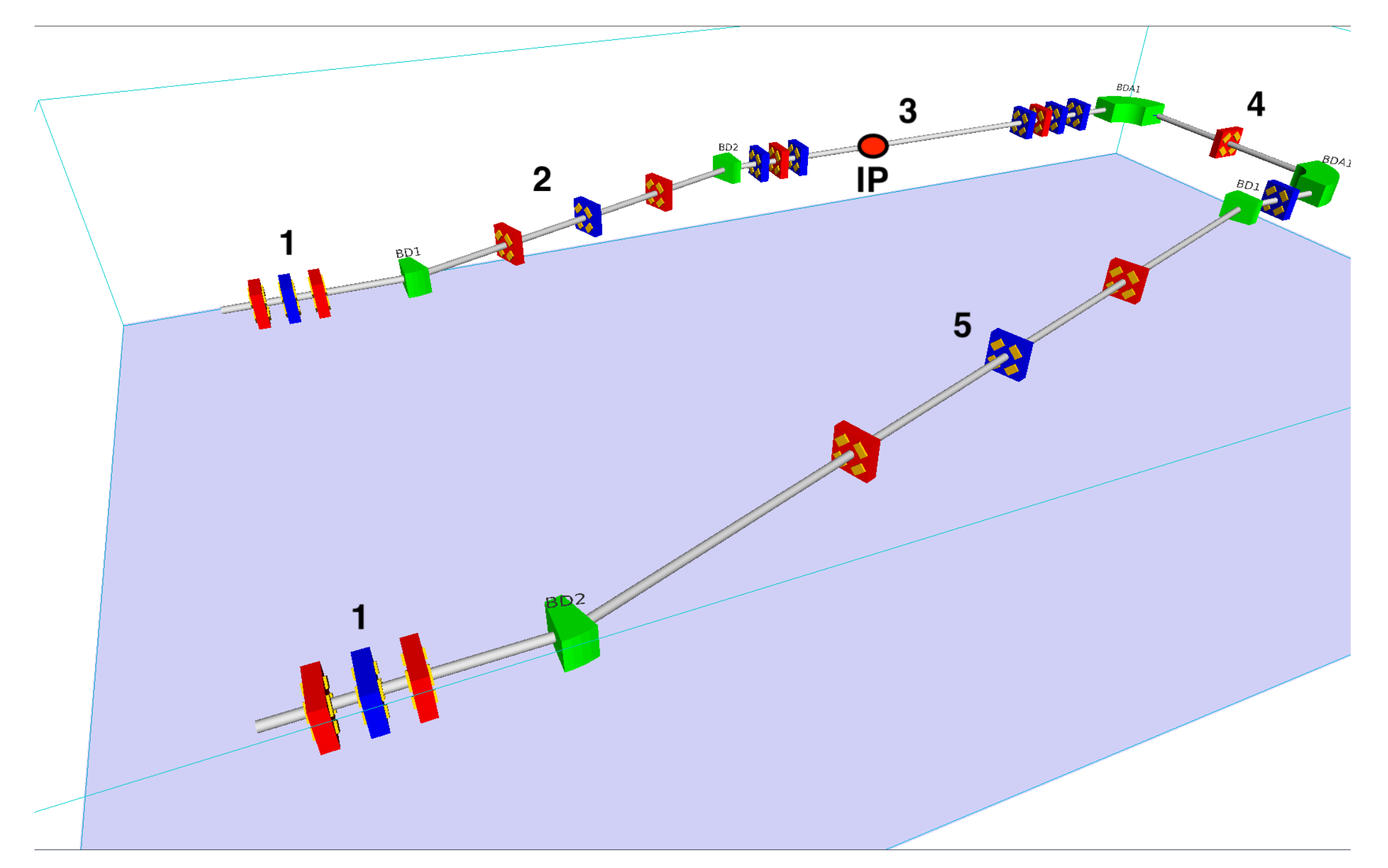
The top view projection of the BriXs scheme in the present configuration with two interaction points (IP) and the floor position of the magnetic elements is shown in
Figure 4. Each branch of the two BriXs beam lines, depicted in
Figure 5, includes the following sections:
a quadrupole triplet (
,
,
in
Figure 4), located downstream the SC Linac ERL1, matches the beam to the first chicane and allows for quadrupole-scan emittance diagnostic; electron bunches travel through these elements in both directions, outgoing from the accelerator or backwards from the specular path;
a dog-leg chicane, composed of two
dipoles (
,
) and three quadrupole lenses (
,
,
in
Figure 4) closing the chicane dispersion, transports the beam to the IP line;
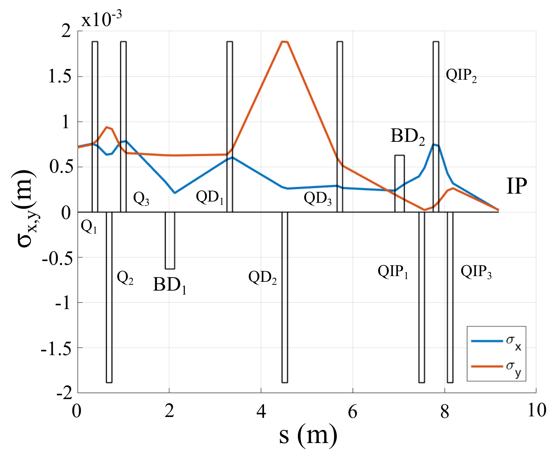
the IP region includes two strong focusing triplets (
,
,
and
,
,
in
Figure 4), symmetrically installed w.r.t. the IP, and the 1 m long Fabri-Pérot Optical Cavity. This section has identity transport matrix, so different focusing settings at IP can be adopted without affecting the magnetic elements downstream. The electron beam rms transverse dimensions from the Linac exit to the interaction point are shown in
Figure 6;
a double bend achromat () section with two dipoles ( and ) and three quadrupoles (, , ) deflects the beam by and closes the dispersion at its end;
a long dog-leg chicane with two dipoles ( and , similar to and ) translates the beam to the second SC Linac; the , , triplets provide control the clearance of the first quads to avoid interference at the X-cross of the two beam lines;
the triplets “1” in
Figure 5 are identical and specular structures.
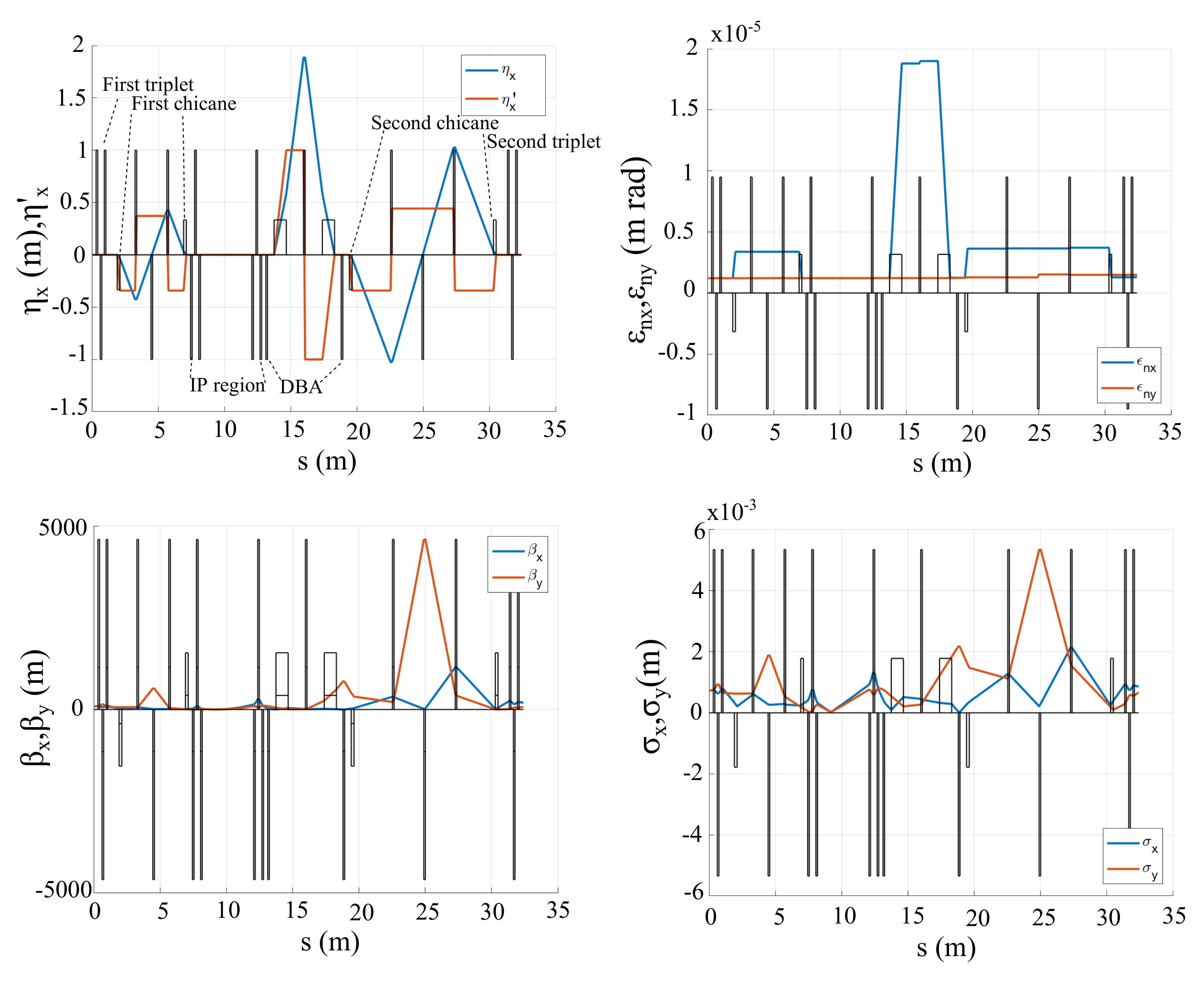
Each of the electron beam lines has been designed so that the dispersion is closed at the IP region (see
Figure 7, top left), at the exit of the DBA (4), where a diagnostic station will be installed and at the exit of the second chicane (5) in order to optimize the beam injection in the recovery Linac.
Figure 7 shows the transverse dispersions (top left box), the normalized emittance (top right box), the beta functions (bottom left box), and the transverse sizes (bottom right box) as a function of the distance
s along the beam line from the Linac exit. The quadrupole strengths
of the various elements are reported in
Table 3 for an electron energy of 100 MeV beam energy.
The transport of the electron beam from the exit of the first ERL, through the IP to the entrance of the second ERL has been performed by Elegant [
8] and is part of start to end simulations.
The main electron beam parameters at the IP are collected in
Table 4.
6. Laser System
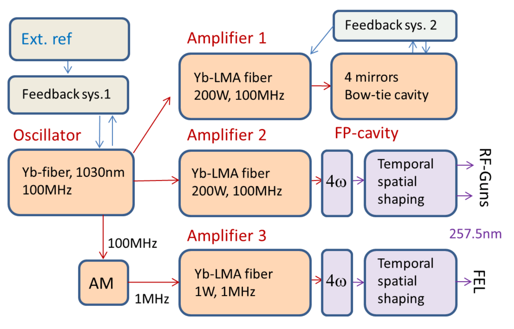
The optical system of MariX is designed to guide both the Compton and the FEL sources with the use of a single laser oscillator. Concerning the Compton source, the laser system delivers the two 100 MHz outputs at 257.5 nm for the two RF-guns and that at 1030 nm for the high finesse cavity. The whole laser is based on Yb-fiber active medium in order to reach the high mean power due to the 100MHz reprate of the system. This system allows for direct pumping with semiconductor lasers at 975 nm, resulting in a high overall efficiency, relatively low cooling requirements and a compact footprint. The output dedicated for the FEL is based on the same technology but the repetition rate is reduced at 1MHz by a commercial amplitude modulator based on a integrated-optical wave guides Mach-Zender interferometer. In
Figure 8 the scheme of the laser system is shown. The oscillator is a commercial mode-locked Yb-fiber laser that delivers a train of pulses at 100 MHz and 1030 nm. Then we have three amplifier systems respectively dedicated to the high finesse cavity, the two RF-guns for the Compton and the line for the FEL system that drives one of the two RF-guns. The amplifiers are based on the CPA (chirped pulse amplification) scheme. The stretcher and the compressor are made by two CVBG (chirped volume Bragg grating) devices and the gain medium is based on a LMA (large mode area) fiber doped with Yb. With this scheme it is possible to reach the required mean power of 200 W with very high stability. The fiber technology, beside the thermal advantages, allows us to obtain both optimal spatial quality and pointing stability, and this is of fundamental importance to coupling efficiently the high finesse cavity and to drive the RF-guns. In order to generate the electron bunches by photo-emission the amplified radiation is upconverted up to the 4th harmonic (257.5 nm) by two non-linear crystals, one LBO crystal in non-critical phase matching configuration, and a couple of CLBO crystals. Both the temporal and the spatial shaping of the laser pulse are implemented in order to reach the minimum level of the emittance in the electron bunches. The temporal shaping is obtained by the stacking method [
9] with three alpha-BBO crystals and the spatial shaping is based on a commercial pi-shaper device and an imaging system. The repetition rate of the laser oscillator is stabilized with respect to an external reference by a feedback system. In the case of the Compton, the external reference could be an RF reference but in the case of a pump and probe experiment with the FEL system, due to the demand of a timing at fs level [
10], we need to stabilize the laser by a balanced cross correlator [
10] with respect to an optical master oscillator. A second feedback system is needed in order to stabilize the high finesse cavity with respect to the laser oscillator. This second feedback is based on the PDH (Pound Drevel Hall) [
11] method and a f2f system [
12]. The first one is exploited in order to stabilize the repetition rate of the high finesse cavity and the second one in order to remove the carrier-envelop-offset from the oscillator spectral comb and in turn to superimpose the oscillator spectral comb with that of the cavity.
7. High Finesse Cavity
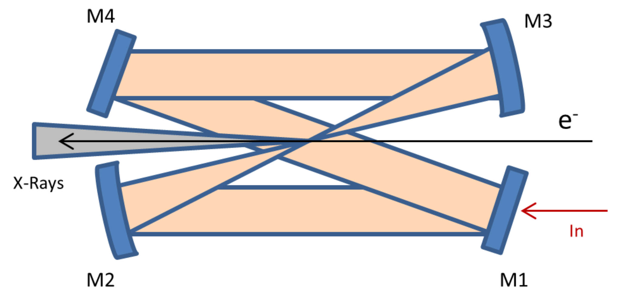
The high finesse cavity we are planning to use for the Compton is a 4 mirrors bow-tie cavity in the crossed configuration (see
Figure 9).
The mirrors M1 and M4 are plane and the mirrors M2 and M3 are concave with a radius of curvature of 750 mm. This kind of cavity allows us to obtain a very high mechanical stability and also provides high flexibility for the adjustments of the cavity round trip frequency (witch must be matched to that of the electrons, that is fixed at 100 MHz) and the laser beam waist. Indeed, it turns out that a length variation between the two flat mirrors changes the cavity round trip length without noticeably changing the laser beam waist. The laser beam waist can thus be set by tuning the distance between the two spherical mirrors independently of the cavity round-trip length. Moreover, when this cavity operates near the edge of the confocal configuration we obtain at the same time the minimum dimension in the focal point and the maximum dimension on all the 4 mirrors allowing the working at the very high mean power required for the Compton, staying below the damage threshold of the mirrors. We plan to inject the cavity with 200 W in order to obtain an internal mean power of 500 kW by a gain factor of 2500. In order to minimize the thermal deformation [
13], and in turn the variation of the mirrors radius of curvature, the substrate of the mirrors M2, M3, M4 is made of ULE (ultra low expansion material) and that of the M1 mirror of Sapphire to transmit efficiently the input beam. Due to the mirror’s encumbrance the collision angle will be around 7 degrees and this introduces an ellipticity in the cavity as a function of spatial shift
between two curved mirrors (M2 and M3) mode as shown in
Figure 9 due to the incidence angle on the curved mirrors. The parameters of the laser at IP are shown in the
Table 5.
8. Expected Performance
The working point is the result of a full start-to-end simulation along all the BriXs electron beam line, from the photocathode to the radiation detector. The electron bunch parameters at IP used in this simulation, as well as the laser and the radiation characteristics, are presented in the first seven lines of
Table 6. The Compton emission has been simulated using the Monte Carlo code CAIN [
14].
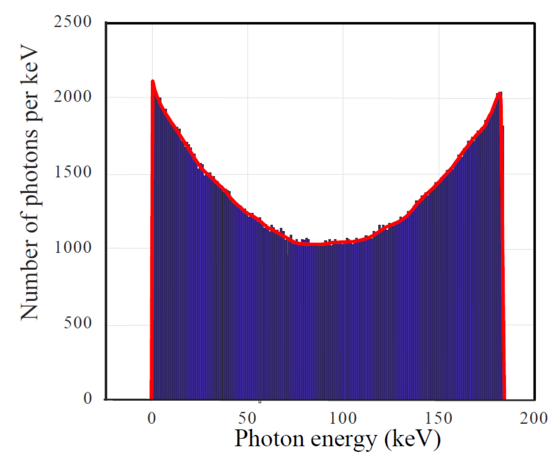
The distribution of the scattered photon total number is presented in
Figure 10 as a function of the photon energy
. In all cases, the emission of X-rays photons at a maximum value of 180 keV does not deteriorate the quality of the electron beam, because the electron recoil is negligible with respect to the initial energy spread. In any way, this effect is taken into account in all simulations. The total number of emitted photons in the full solid angle attains
per shot. Due to the boosted nature of the Compton back scattering process,
where
is the electron Lorentz factor,
is the interaction angle,
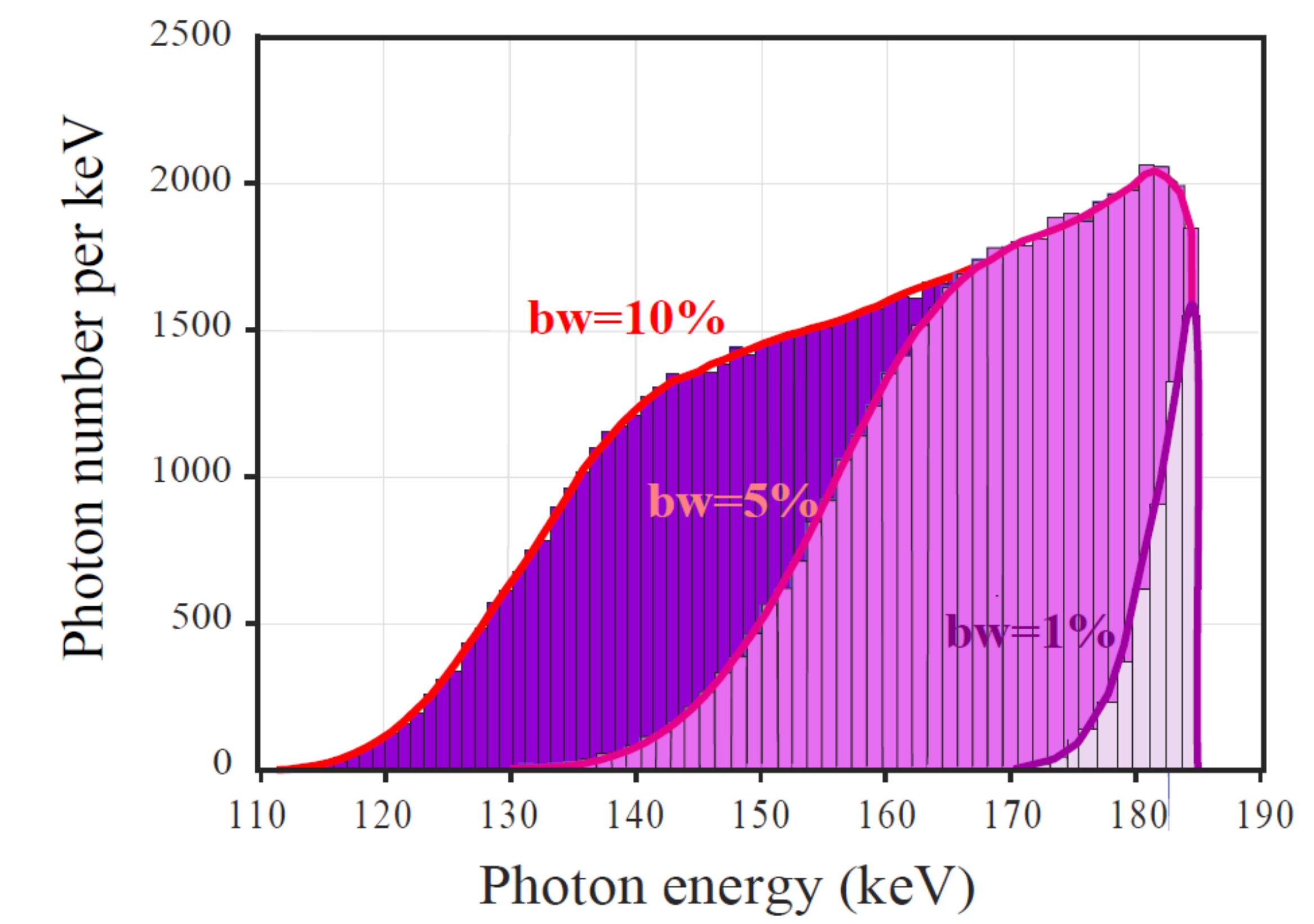
is the emission angle, the radiation exhibits an energy-angle correlation with the most energetic photons emitted on axis, while the outer regions are occupied by low energy photons. This feature makes it possible to get monochromatic radiation by inserting irides or collimators along the path of the radiation, selecting therefore only the photons within a given collimation angle
.
Figure 11 presents the spectrum of the radiation collimated respectively in the angles:
mrad, leading to a bandwidth of
,
mrad with
and
mrad with a corresponding bandwidth of
. The number of collimated photons per shot, about
in
bandwidth, increases to
for
of bandwidth and to
for
of bandwidth, giving respectively
,
and
photons per second.
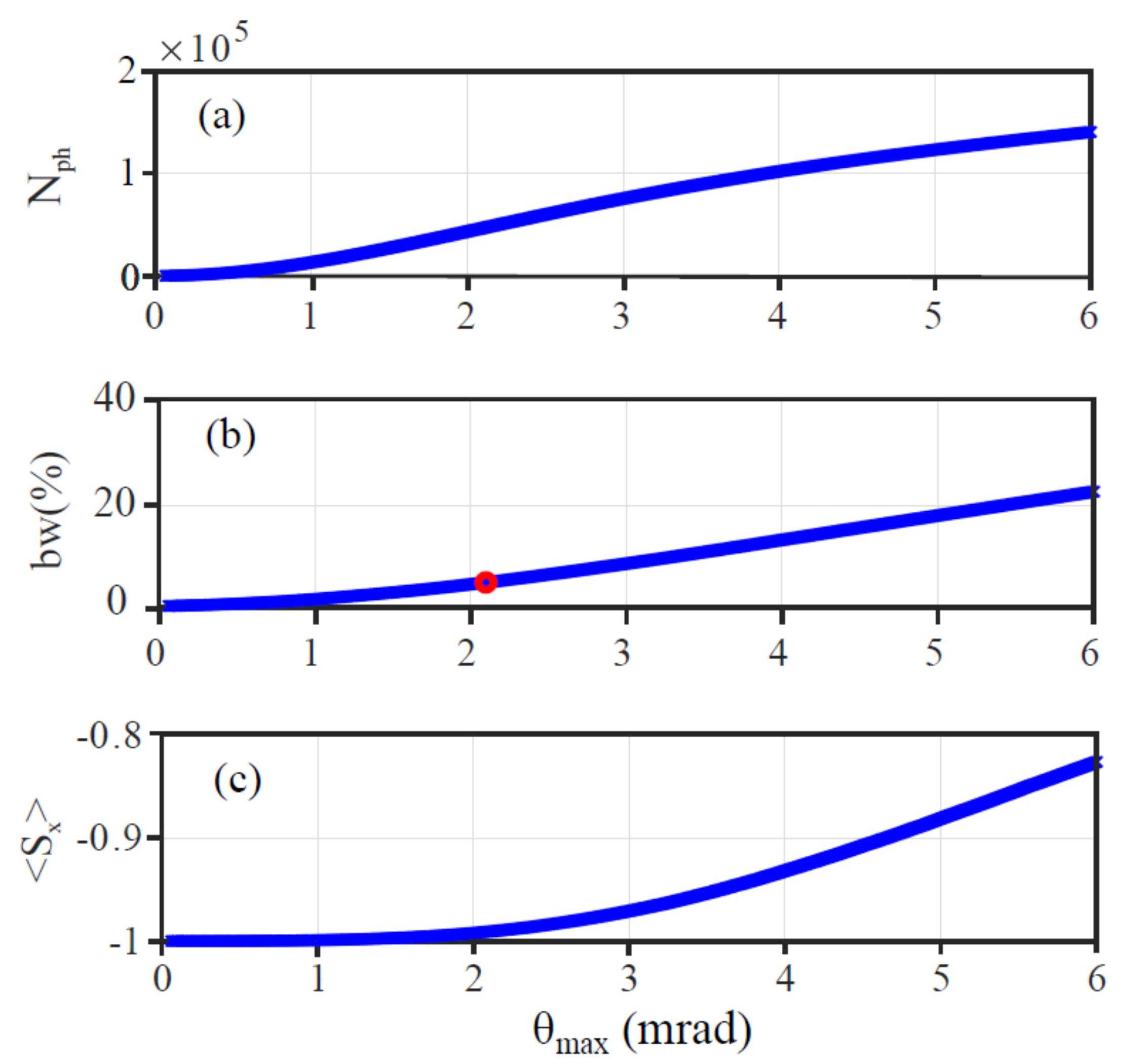
The dependence of the number of the scattered photons
, bandwidth
and average Stoke parameter
on the collimation angle
is reported in
Figure 12. The polarization [
15] slightly decreases with increasing angles but remains always well above
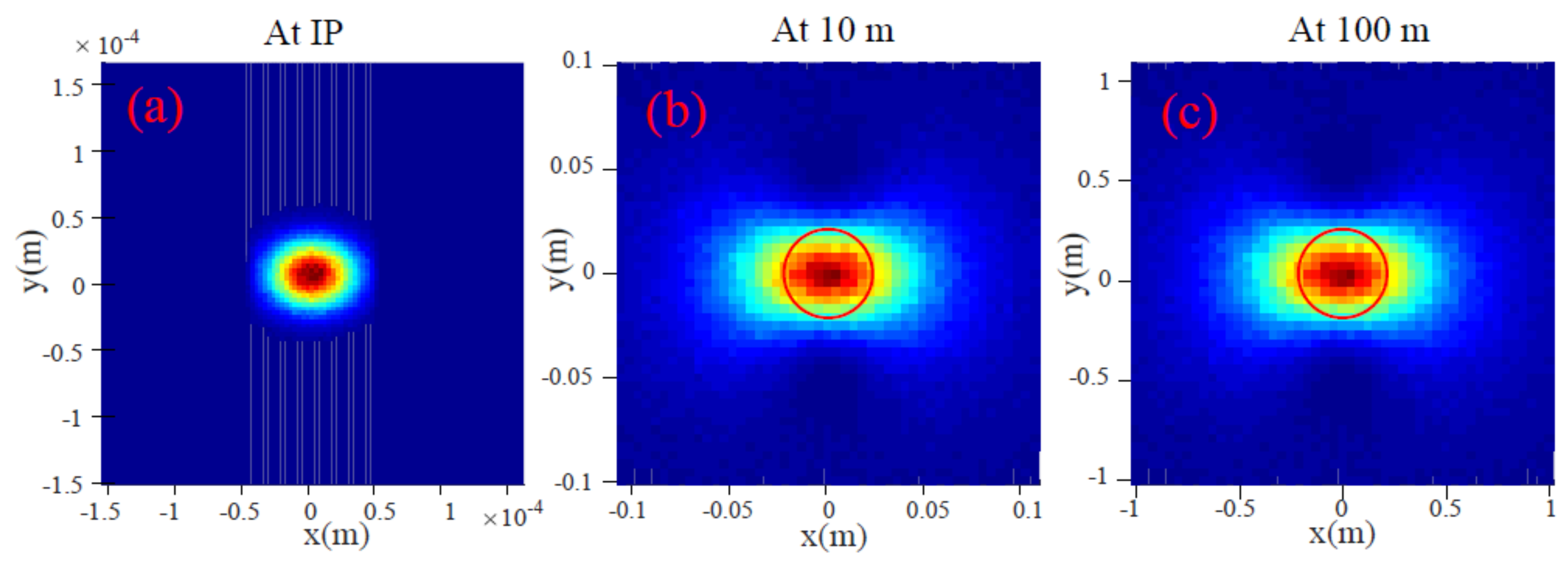
in total and even more in the collimated region. The photon intensity on a screen perpendicular to the electron beam at various distances are presented in
Figure 13.
The electron beam parameters, as well as the laser and radiation characteristics, are reported in
Table 7 for the low energy working point. Consistent with the results from the injector and Linac simulations, we assumed for this case an
MeV electron beam, an emittance slightly larger than the previous case and a higher energy spread, with therefore an overall lower quality. The focusing was slightly increased, reaching values of
≃
m, to compensate for those characteristics. However, the bandwidth is dominated toward the lower values by the larger emittance and energy spread and cannot be lowered below
. The total number of photons turns out to be
, while the collimated photons in
mrad and in
mrad (corresponding to
and
of bandwidth) are respectively
and
per shot. Regarding the photon flux, we have
for
of bandwidth and
for
. Important applications require two color operation and therefore all Compton sources, based on both operation in Fabry-Perot cavities and on single laser shot, consider various different techniques for producing such radiation. As per Equation (
1), the energy of scattered photons also depends on the initial collision angle
. This dependence can be exploited, conceiving a two color radiation scheme based on the use of two laser pulses impinging on the same electron beam at two different angles [
16]. The potentialities of this scheme can be improved by using laser pulses carrying different polarizations. Furthermore, the extension to the production of a sequence of two different colors and time separated X-ray pulses is important for adjusting the time needed by the detectors to record and load two images at two different colors, which is mandatory for digital subtraction.

 ,
, 


