Investigation on the Performance Improvement of Polyacrylonitrile-Derived Flexible Electrospun Carbon Nanofiber Mats

 ,
,
Abstract
:
1. Introduction
2. Experimental Sections
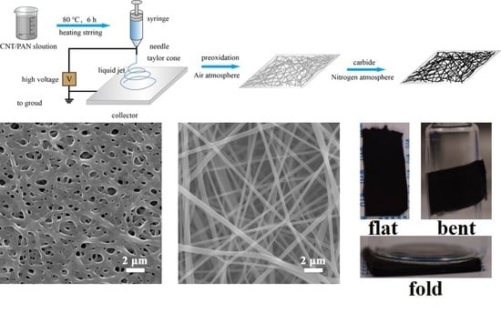
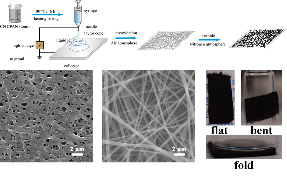
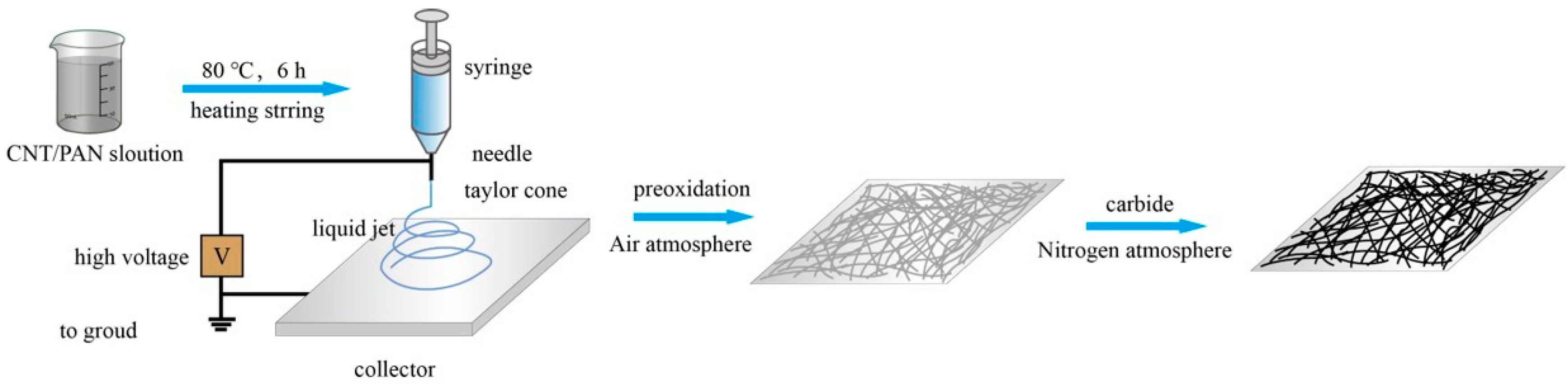
2.1. Fabrication of Electrospun Carbon Nanofiber Mats
2.2. Structure, Morphology and Electrochemical Characterization
3. Results and Discussions
4. Conclusions
Supplementary Materials
Author Contributions
Funding
Conflicts of Interest
References
- Samuel, E.; Jo, H.S.; Joshi, B.; An, S.; Park, H.G.; Kim, Y.; Yoon, W.Y.; Yoon, S.S. Decoration of MnO nanocrystals on flexible freestanding carbon nanofibers for lithium ion battery anodes. Electrochim. Acta 2017, 231, 582–589. [Google Scholar] [CrossRef]
- Joshi, B.N.; An, S.; Kim, Y.I.; Samuel, E.P.; Song, K.Y.; Seong, I.W.; Al-Deyab, S.S.; Swihart, M.T.; Yoon, W.Y.; Yoon, S.S. Flexible freestanding Fe2O3-SnO-carbon nanofiber composites for Li ion battery anodes. J. Alloys Comp. 2017, 700, 259–266. [Google Scholar] [CrossRef]
- Yu, M.; Wang, Z.; Wang, Y.; Dong, Y.; Qiu, J. Freestanding flexible Li2S paper electrode with high mass and capacity loading for high-energy Li-S batteries. Adv. Energy Mater. 2017, 7, 1700018. [Google Scholar] [CrossRef]
- Ding, X.; Zhou, H.; Wang, M.; Chen, M.; Li, L.; Yang, Z.; Wang, X. High rate performance and long cycle stability of lithium manganate nanofibers by tuned pre-oxidation treatment. J. Alloys Comp. 2017, 724, 975–980. [Google Scholar] [CrossRef]
- Peng, Y.; Zhang, Y.; Wang, Y.; Shen, X.; Wang, F.; Li, H.; Hwang, B.J.; Zhao, J. Directly coating a multifunctional interlayer on the cathode via electrospinning for advanced lithium-sulfur batteries. ACS App. Mater. Interfaces 2017, 9, 29804–29811. [Google Scholar] [CrossRef] [PubMed]
- Xiao, F.; Guo, X.; Li, J.; Sun, H.; Zhang, H.; Wang, W. Electrospinning preparation and dye adsorption capacity of TiO2@carbon flexible fiber. Ceram. Int. 2019, 45, 11856–11860. [Google Scholar] [CrossRef]
- Wang, X.; Hu, X.; Huang, J.; Zhang, W.; Ji, W.; Hui, Y.; Yao, X. Electrospinning synthesis of porous carbon fiber supported Pt-SnO2 anode catalyst for direct ethanol fuel cell. Solid State Sci. 2019, 94, 64–69. [Google Scholar] [CrossRef]
- Yun, S.I.; Kim, S.H.; Kim, D.W.; Kim, Y.A.; Kim, B.H. Facile preparation and capacitive properties of low-cost carbon nanofibers with ZnO derived from lignin and pitch as supercapacitor electrodes. Carbon 2019, 149, 637–645. [Google Scholar] [CrossRef]
- Dong, X.; Guo, Z.; Song, Y.; Hou, M.; Wang, J.; Wang, Y.; Xia, Y. Flexible and wire-shaped micro-supercapacitor based on Ni(OH)2-nanowire and ordered mesoporous carbon electrodes. Adv. Funct. Mater. 2014, 24, 3405–3412. [Google Scholar] [CrossRef]
- Ng, C.H.; Lim, H.N.; Lim, Y.S.; Chee, W.K.; Huang, N.M. Fabrication of flexible polypyrrole/graphene oxide/manganese oxide supercapacitor. Int. J. Energy Res. 2015, 39, 344–355. [Google Scholar] [CrossRef]
- Shao, Y.; El-Kady, M.F.; Sun, J.; Li, Y.; Zhang, Q.; Zhu, M.; Wang, H.; Dunn, B.; Kaner, R.B. Design and mechanisms of asymmetric supercapacitors. Chem. Rev. 2018, 118, 9233–9280. [Google Scholar] [CrossRef] [PubMed]
- Couly, C.; Alhabeb, M.; Van Aken, K.L.; Kurra, N.; Gomes, L.; Navarro-Suárez, A.M.; Anasori, B.; Alshareef, H.N.; Gogotsi, Y. Asymmetric flexible MXene-reduced graphene oxide micro-supercapacitor. Adv. Electron. Mat. 2018, 4, 1700339. [Google Scholar] [CrossRef]
- Souza, V.H.R.; Oliveira, M.M.; Zarbin, A.J.G. Bottom-up synthesis of graphene/polyaniline nanocomposites for flexible and transparent energy storage devices. J. Power Sources 2017, 348, 87–93. [Google Scholar] [CrossRef]
- Zhou, C.; Yang, Y.; Sun, N.; Wen, Z.; Cheng, P.; Xie, X.; Shao, H.; Shen, Q.; Chen, X.; Liu, Y.; et al. Flexible self-charging power units for portable electronics based on folded carbon paper. Nano Res. 2018, 11, 4313–4322. [Google Scholar] [CrossRef]
- Kumar, S.; Nehra, M.; Kedia, D.; Dilbaghi, N.; Tankeshwar, K.; Kim, K.H. Carbon nanotubes: A potential material for energy conversion and storage. Prog. Energy Combust. Sci. 2018, 64, 219–253. [Google Scholar] [CrossRef]
- Hu, Y.; Guo, P.; Thompson, J.; Wang, Z. Rational design of mesoporous LiFePO4@C nanofibers as cathode materials for energy storage. Ceram. Int. 2017, 43, 10201–10206. [Google Scholar] [CrossRef]
- Wang, X.; Xi, M.; Wang, X.; Fong, H.; Zhu, Z. Flexible composite felt of electrospun TiO2 and SiO2 nanofibers infused with TiO2 nanoparticles for lithium ion battery anode. Electrochim. Acta 2016, 190, 811–816. [Google Scholar] [CrossRef]
- Nan, W.; Zhao, Y.; Ding, Y.; Shende, A.R.; Fong, H.; Shende, R.V. Mechanically flexible electrospun carbon nanofiber mats derived from biochar and polyacrylonitrile. Mater. Lett. 2017, 205, 206–210. [Google Scholar] [CrossRef]
- Ning, H.; Xie, H.; Zhao, Q.; Liu, J.; Tian, W.; Wang, Y.; Wu, M. Electrospinning ZnO/carbon nanofiber as binder-free and self-supported anode for Li-ion batteries. J. Alloys Compd. 2017, 722, 716–720. [Google Scholar] [CrossRef]
- Vijayan, B.L.; Krishnan, S.G.; Zain, N.K.M.; Harilal, M.; Yar, A.; Misnon, I.I.; Dennis, J.O.; Yusoff, M.M.; Jose, R. Large scale synthesis of binary composite nanowires in the Mn2O3-SnO2 system with improved charge storage capabilities. Chem. Eng. J. 2017, 327, 962–972. [Google Scholar] [CrossRef]
- Qin, R.; Shao, G.; Hou, J.; Zheng, Z.; Zhai, T.; Li, H. One-pot synthesis of Li3VO4@C nanofibers by electrospinning with enhanced electrochemical performance for lithium-ion batteries. Sci. Bull. 2017, 62, 1081–1088. [Google Scholar] [CrossRef]
- Mao, M.; Yan, F.; Cui, C.; Ma, J.; Zhang, M.; Wang, T.; Wang, C. Pipe-wire TiO2-Sn@carbon nanofibers paper anodes for lithium and sodium ion batteries. Nano Lett. 2017, 17, 3830–3836. [Google Scholar] [CrossRef] [PubMed]
- Ding, X.; Li, Y.; Si, Y.; Yin, X.; Yu, J.; Ding, B. Electrospun polyvinylidene fluoride/SiO2 nanofibrous membranes with enhanced electret property for efficient air filtration. Compos. Commun. 2019, 13, 57–62. [Google Scholar] [CrossRef]
- Khatti, T.; Naderi-Manesh, H.; Kalantar, S.M. Application of ANN and RSM techniques for modeling electrospinning process of polycaprolactone. Neural Comput. Appl. 2017, 31, 239–248. [Google Scholar] [CrossRef]
- Wang, Z.; Song, G.; Xu, J.; Fu, Q.; Pan, C. Electrospun titania fibers by incorporating graphene/Ag hybrids for the improved visible-light photocatalysis. Front. Mat. Sci. 2018, 12, 379–391. [Google Scholar] [CrossRef]
- Perera Jayawickramage, R.A.; Balkus, K.J.; Ferraris, J.P. Binder free carbon nanofiber electrodes derived from polyacrylonitrile-lignin blends for high performance supercapacitors. Nanotechnology 2019, 30, 355402. [Google Scholar] [CrossRef] [PubMed]
- Duan, Q.; Wang, B.; Wang, H. Effects of stabilization temperature on structures and properties of polyacrylonitrile (PAN)-based stabilized electrospun nanofiber mats. J. Macromol. Sci. Part B 2012, 51, 2428–2437. [Google Scholar] [CrossRef]
- Lei, S.; Cao, W.; Fu, Z.; Xu, L. The conjugated plane formed in polyacrylonitrile during thermal stabilization. J. Appl. Polym. Sci. 2016, 133, 43890. [Google Scholar] [CrossRef]
- Song, C.; Wang, T.; Qiu, Y.; Qiu, J.; Cheng, H. Effect of carbonization atmosphere on the structure changes of PAN carbon membranes. J. Porous Mater. 2009, 16, 197–203. [Google Scholar] [CrossRef]


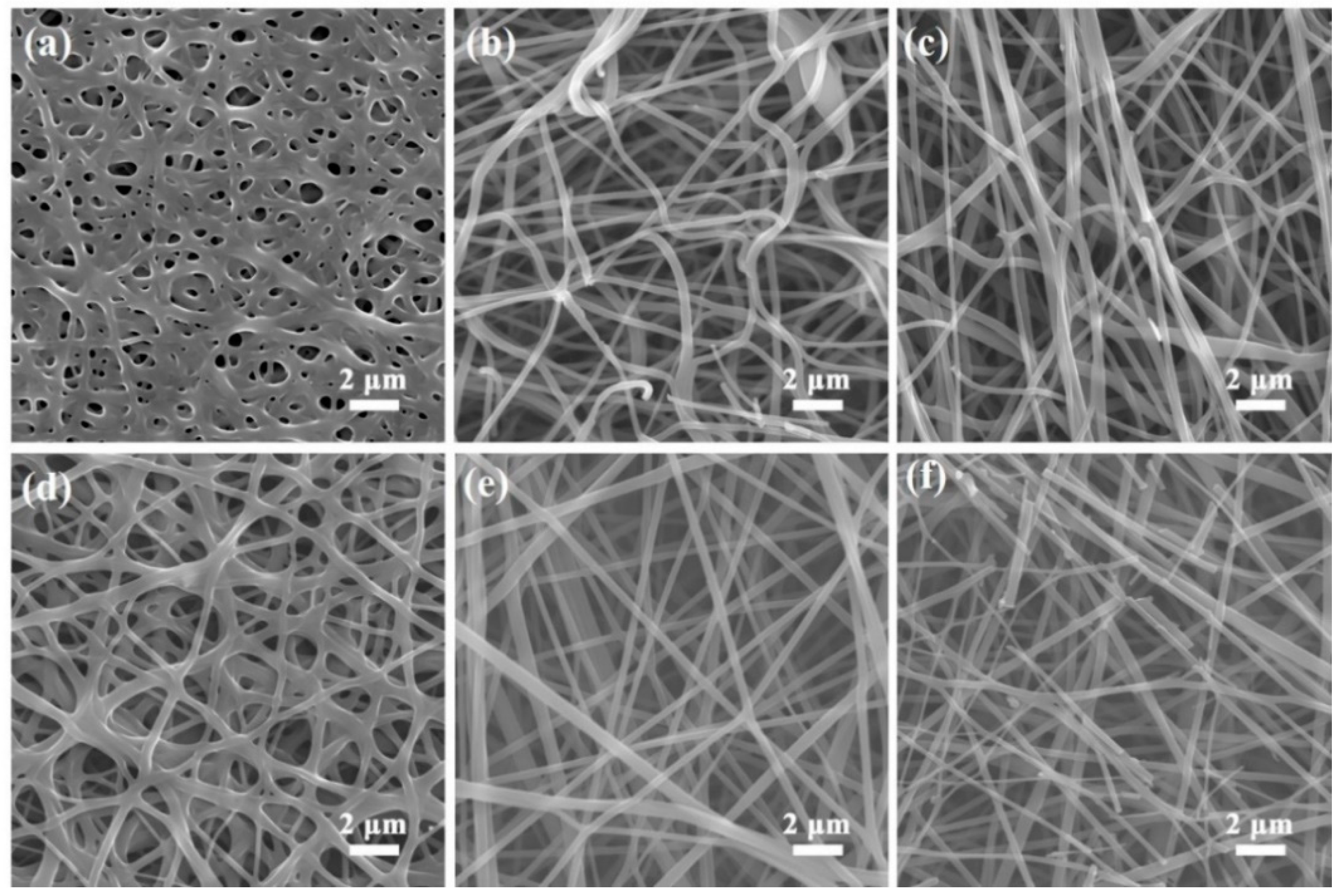
| Sample | Thermal Stabilization Temperature (°C) | Carbonization Temperature (°C) | Sheet Resistance (Ω/sq) | Average Diameter (nm) |
|---|---|---|---|---|
| C-1 | 220 | 800 | 665 | Interconnected networks |
| C-2 | 250 | 800 | 661 | 200 |
| C-3 | 270 | 800 | 651 | 200 |
| C-4 | 300 | 800 | 517 | 300 |
| C-5 | 270 | 900 | 154 | 200 |
| C-6 | 270 | 1000 | 116 | 200 |
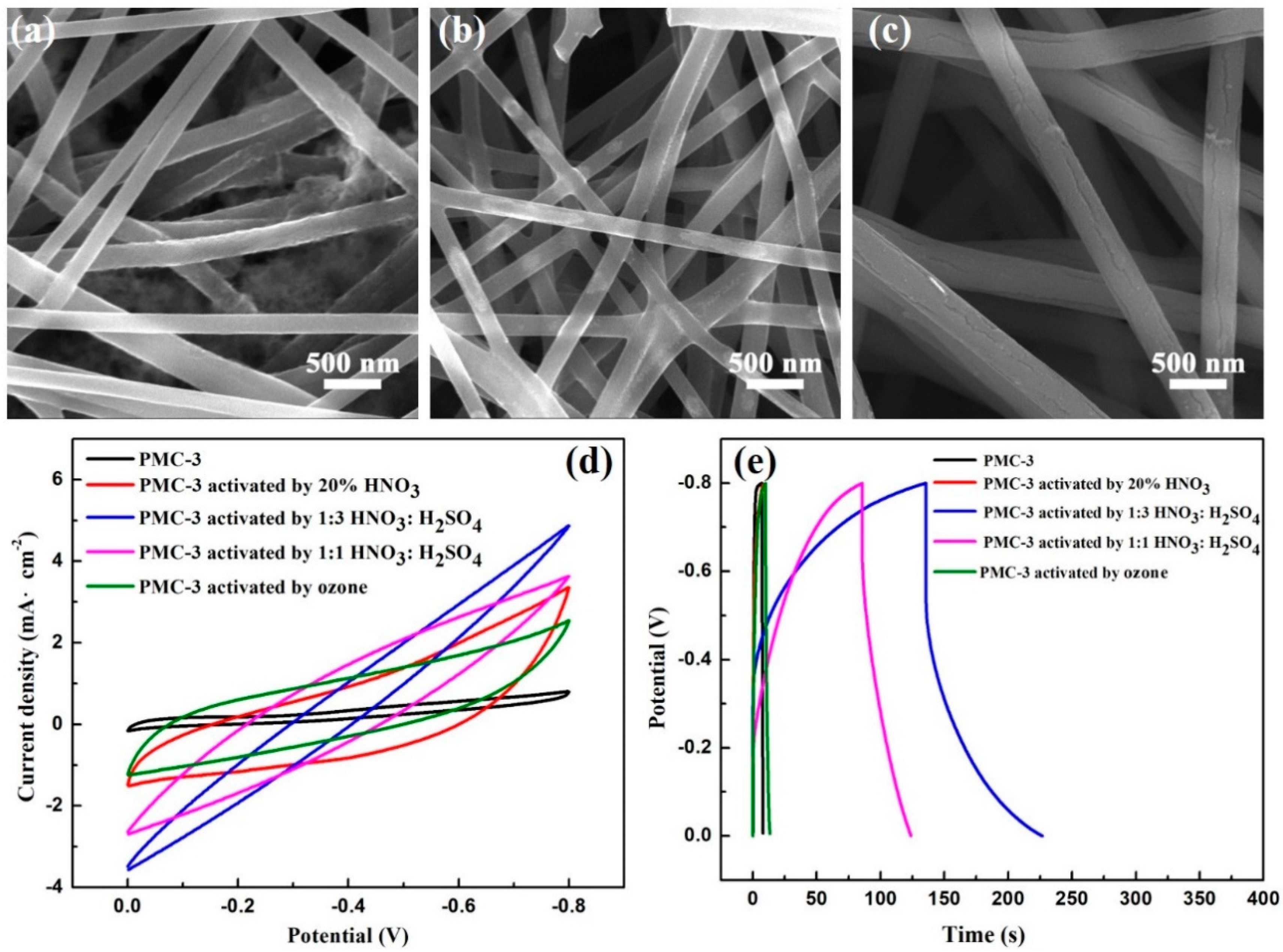
| Sample | Quantity of MWCNTs (g) | Mass Fraction of MWCNTs (%) | Sheet Resistance (Ω/sq) | Average Diameter (nm) |
|---|---|---|---|---|
| PMC-1 | 0.05 | 0.7 | 66 | 140 |
| PMC-2 | 0.10 | 1.5 | 59 | 230 |
| PMC-3 | 0.15 | 2.4 | 60 | 240 |
| Activating Agent | Activation Method | Treatment Time |
|---|---|---|
| 20 wt% HNO3 | Immersion with ultrasonic processing | 6 h |
| 1:3 HNO3:H2SO4 | Immersion with ultrasonic processing | 6 h |
| 1:1 HNO3:H2SO4 | Immersion with ultrasonic processing | 6 h |
| Ozone | Ozone treatment | 1 h |
© 2019 by the authors. Licensee MDPI, Basel, Switzerland. This article is an open access article distributed under the terms and conditions of the Creative Commons Attribution (CC BY) license (http://creativecommons.org/licenses/by/4.0/).
Share and Cite
He, X.; Lan, Q.; Zhao, S.; Liu, J.; Zhang, C.; Chen, B.; Chen, M.; Song, M. Investigation on the Performance Improvement of Polyacrylonitrile-Derived Flexible Electrospun Carbon Nanofiber Mats. Appl. Sci. 2019, 9, 3683. https://doi.org/10.3390/app9183683
He X, Lan Q, Zhao S, Liu J, Zhang C, Chen B, Chen M, Song M. Investigation on the Performance Improvement of Polyacrylonitrile-Derived Flexible Electrospun Carbon Nanofiber Mats. Applied Sciences. 2019; 9(18):3683. https://doi.org/10.3390/app9183683
Chicago/Turabian StyleHe, Xin, Qiuming Lan, Sirou Zhao, Junyan Liu, Chi Zhang, Bohua Chen, Mei Chen, and Mingxia Song. 2019. "Investigation on the Performance Improvement of Polyacrylonitrile-Derived Flexible Electrospun Carbon Nanofiber Mats" Applied Sciences 9, no. 18: 3683. https://doi.org/10.3390/app9183683