
Abstract
We describe a novel method for providing geometrical on-axis access to an optical enhancement resonator through an on-axis aperture at one of its mirrors. A superposition of transverse modes in a stable degenerate resonator is used to form a field distribution which avoids the aperture and therefore exhibits small loss. Upon propagation in the resonator the modes acquire a different phase, and an on-axis intensity maximum is formed at a different position. We call this a quasi-imaging resonator, because it is related to imaging in the sense that a hole in the field distribution, exacted by the aperture, is reproduced after a resonator round trip.
Export citation and abstract BibTeX RIS

Content from this work may be used under the terms of the Creative Commons Attribution 3.0 licence. Any further distribution of this work must maintain attribution to the author(s) and the title of the work, journal citation and DOI.
1. Introduction
Passive optical resonators serve manifold purposes. The many round trips the radiation takes depending on the resonator loss lead to an increased sensitivity that is used in metrology [1, 2], and to an enhanced intensity that is e.g. used for nonlinear processes like frequency conversion or processes with a small cross section like Thomson back-scattering at electrons [3]. For many applications an access along the optical axis of the resonator is necessary to couple radiation in or out. This can often be achieved with dichroic mirrors. For some applications a geometrical access along the optical axis is desirable, e.g. if there are no dichroic mirrors available for the given wavelengths. The particular problem that motivated the present work is the output coupling of high harmonics generated in a gas jet near the focus of a femtosecond enhancement resonator [4, 5]. Depending on the application, geometrical output coupling through an opening in a resonator mirror can be advantageous compared to alternative methods: there is no additional optical element in the resonator and hence no additional dispersion, nonlinearity, bandwidth limitation or polarization discrimination for the fundamental radiation, and the harmonics are not angularly dispersed.
A geometrical access constitutes an obstacle affecting the resonant field distribution, and in general introduces loss, limiting the circulating power. We propose a quasi-imaging enhancement resonator, which is a resonator with a degeneracy of transverse modes and an obstacle in the beam path (figure 1). Simultaneously resonant transverse modes combine to a field distribution avoiding the obstacle. Field distributions with an on-axis intensity maximum at a different position can be excited. This basic concept has been proposed in active resonators for free electron lasers, where holes in resonator mirrors allow to introduce the electron beam in a collinear fashion [6]. We apply it to passive enhancement resonators for nonlinear processes. We experimentally demonstrated this concept in [7], and proved the suitability of the field distribution for high harmonic generation (HHG) in [8]. Here, we present an analytical formalism for the description of tailoring the transverse mode of a high-finesse resonator by means of quasi-imaging.
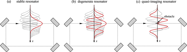
Figure 1. A schematic illustration of the concept of quasi-imaging. (a) In a stable resonator the transverse modes generally have a different round-trip phase and only one mode can be simultaneously resonant (red = resonant, gray = non-resonant). (b) In the case of a degenerate resonator a subset of transverse modes have the same round-trip phase and can be simultaneously resonant. The resonant transverse modes propagate independently in the resonator, i.e. the relative amplitude and phase are arbitrary. (c) A quasi-imaging resonator is a degenerate resonator with an obstacle in the beam path. This obstacle leads to a coupling of the transverse modes and determines their relative amplitude and phase. Mode combinations avoiding the obstacle can be considered eigen-modes of the quasi-imaging resonator. We call this situation 'quasi-imaging' because it is related to imaging in the sense that a hole in the field distribution, exacted by the obstacle, is reproduced after a resonator round trip.
Download figure:
Standard image High-resolution imageThe manuscript is structured as follows: section 2 gives an introduction to resonator stability and the concept of quasi-imaging; section 3 describes possible eigen-modes of a quasi-imaging resonator. In section 4 an advantageous resonator design is discussed. In section 5 we argue how a Gaussian beam can be adapted for maximal spatial overlap with an eigen-mode of a quasi-imaging resonator. Section 6 introduces a rigorous model describing the sensitivity against detuning from the degeneracy and against aberrations. In section 7 we compare the concept of a quasi-imaging resonator to an imaging resonator. In section 8 the application of HHG and other concepts for a geometrical on-axis access are discussed and section 9 concludes the paper.
2. Resonator stability
In the geometrical optics description, an optical resonator is stable if a ray with an angle or offset to the optical axis stays within the optical system as it completes many resonator round trips, whereas in an unstable resonator such a ray eventually leaves the system, because the transverse offset grows unlimitedly. In both cases there exist eigen-modes of the electric field, i.e. transverse field distributions that are reproduced after one resonator round trip, possibly with a round-trip loss. For a stable resonator with spherical mirrors these eigen-modes are in paraxial approximation the orthogonal set of Gauss−Hermite modes GHn,m, with mode order n and m in the transverse directions x and y [9]. These modes do not experience diffraction loss, provided that the mirrors are sufficiently large. This is due to the fact that the field is restricted to a region around the optical axis. In an unstable resonator the eigen-modes have in general to be computed numerically [10]. They depend on the extension of the mirrors (or other apertures) and exhibit a mode-dependent diffraction loss. A resonator with an obstacle on the optical axis can in this sense be viewed as an unstable resonator, irrespective of the stability of an equivalent resonator without the obstacle. Laser resonators with on-axis holes in a mirror have been studied in the past [11–14], serving as output coupler for the fundamental radiation, for mode shaping to improve mode-matching with the gain volume and to increase the mode selectivity.
The stability of a spherical resonator depends on the radii of curvature and distances of the mirrors and possibly on further optical elements. It can be expressed in terms of the elements of the resonator beam transfer matrix for one round trip M = [[A, B],[C, D]]. This matrix can be different for the two transverse directions x and y due to astigmatic elements like Brewster-cut surfaces or curved mirrors with a non-zero angle of incidence. Thus, also the stability range in the transverse directions can be different. For each transverse direction the stability range is given by [9]

This condition follows from the requirement that the eigen-q-parameter qE (in the considered transverse direction) has a finite imaginary part defining the Rayleigh length zR,E of the eigen-mode. The eigen-q-parameter is the q-parameter, which is reproduced after one resonator round trip according to the ABCD-law: qE = (A qE + B)/(C qE + D). From this follows
where AD − BC = 1 was used. The on-axis phase ϕk,n,m acquired by a Gauss−Hermite mode GHn,m with wave number k at a resonator roundtrip with resonator length L (length of a ring resonator or twice the length of a linear resonator) is
with the Gouy parameters ψE,x and ψE,y, which indicate contributions from the field confinement in the transverse directions x and y to the on-axis phase, and thereby determine the phase acquired by a GH mode in addition to a plane wave. They are given by the accumulated Gouy phase shifts ψ from propagation in the resonator. For propagation along the longitudinal coordinate z through a beam waist at position z = 0 with Rayleigh length zR the Gouy phase shift ψ is (in each transverse direction) given by [9]
The Gouy parameter ψE for one resonator round trip can therefore be calculated by adding the contributions from the propagation in the different sections of the resonator, knowing the respective Rayleigh lengths and waist positions. It can, however, also be read from the beam transfer matrix for one round trip. This is analogous to the eigen-q-parameter, which can also be calculated from the elements of the beam transfer matrix according to (2). It can be deduced as follows. The accumulated Gouy phase shift ψ that a Gaussian beam with an arbitrary q-parameter q = z0 + izR acquires in an optical system described by a beam transfer matrix with elements A, B, C, D (an optical system in general or a stable resonator considered here) is [15]
For the Gouy parameter ψE, i.e. the accumulated Gouy phase shift ψ which is acquired by the Gaussian eigen-mode, it follows with the eigen-q-parameter of the resonator (see (2))

This means that within the stability range given by (1) the Gouy parameter ψE runs from 0 to π or from π to 2π, possibly with multiples of 2π added.
If a resonator has cylindrical symmetry, there is only one eigen-q-parameter and Gouy parameter ψE,r and the Gauss−Laguerre modes GLlp with radial and azimuth mode number p and l can be used instead of the GH modes [9]. The on-axis phase per resonator round trip is

Both descriptions (GH and GL modes) assume that the field can be written as a product of the field distribution in the two transverse directions (stigmatic or simple astigmatic systems), which is true only if these directions are not coupled. A coupling can be due to a beam path which is not aligned coplanar (or in a well-defined three-dimensional beam path) [16] or due to cylindrical elements with an angle to the distinguished directions which can e.g. be introduced by small (<λ/10) imperfections of a mirror surface. This case of general astigmatic systems is not treated here [17, 18].
It follows from (3) and (7) that in general transverse modes have different wave numbers k in a resonator with length L, and that transverse modes with the same wave number are resonant at different resonator lengths. For this reason a passive resonator acts as a mode filter [19] as well as a frequency filter. However, for distinguished values of the Gouy parameter ψE,x = 2π/Δn or an integer multiple thereof, modes with mode number difference Δn = 3, 4, 5... are degenerate (simultaneously resonant), because their round-trip phase difference is a multiple of 2π. A degeneracy with a mode number difference Δn = 1 or Δn = 2 cannot be achieved in a stable resonator, because a Gouy parameter ψE,x = 2π or ψE,x = π is not compatible with the stability condition (1). In cylindrical symmetry a transverse mode degeneracy for a radial mode number difference Δp = 2, 3... is achieved with ψE,r = π/Δp or an integer multiple thereof. The properties of such a transverse degenerate passive resonator have been discussed by Gigan et al [20]. An arbitrary combination of the resonant modes, depending on the field impinging on the resonator, can be enhanced. In the case of a transverse degeneracy in a resonator with an obstacle placed in the beam path, the circulating mode combination is determined by the impinging field and the obstacle, as will be discussed in section 6. We call this situation quasi-imaging because it is related to imaging since a hole in the field distribution, exacted by the obstacle, is reproduced after a resonator round trip. The resonant GH or GL modes defining the circulating field acquire different phases at propagation and therefore the shape of the field changes within the resonator. Due to the degeneracy, after one resonator round trip the modes are added with the same relative phase and therefore reproduce the shape of the field and the hole. The fact that a combination of GL modes reproduces its shape at propagation has been discussed and called self-imaging by Courtial [21].
Quasi-imaging can also be viewed as imaging after Δn round trips. In the middle of the stability range with ψE,x = π/2 or 3π/2, i.e. Δn = 4 the equality A + D = 0 holds. Here the resonator beam transfer matrix is M = [[0, zR],[−1/zR, 0]] starting the round trip at the beam waist with Rayleigh length zR. After two and four round trips it is M2 = [[–1, 0],[0, –1]] and M4 = [[1, 0],[0, 1]], respectively. More generally, MΔn = [[1, 0],[0, 1]] for ψE,x = 2π/Δn, Δn  N holds.
3. Eigen-modes of a quasi-imaging resonator
3.1. Construction of hole modes and slit modes
If an obstacle is placed in the beam path of a stable resonator the GH or GL modes are no longer the resonator eigen-modes, unless the transverse extension of the obstacle is sufficiently small and it is placed at a zero of the electric field [22]. The new eigen-modes of the resonator with an obstacle are in general afflicted with diffraction loss. However, in the case of a quasi-imaging resonator, where a set of GH or GL modes is degenerate, new eigen-modes can be simply constructed as a linear combination thereof. If such a linear combination avoids the obstacle it can be considered a new eigen-mode with small diffraction loss. In order to set the field exactly to zero on a finite area, the number of modes would have to be infinite. Therefore, the diffraction loss cannot reach zero. It can, however, for a suitable obstacle be very small for the combination of just a few modes.
Of particular interest is an on-axis obstacle that is e.g. formed by a hole or slit in a resonator mirror. Mode combinations of GH modes avoiding a slit-shaped obstacle we call 'slit modes', mode combinations of GL modes avoiding a hole we call 'hole modes'. Depending on the geometry of the resonator and the Gouy parameter, i.e. mode number difference, numerous mode combinations avoiding an on-axis obstacle can be constructed. The simplest fashion to achieve a vanishing on-axis field at the position of the obstacle is to combine the fundamental mode with the next resonant even transverse mode. For ψE = π/2 or 3π/2 it is Δn = 4 and Δp = 2 and the mode combinations are GH0,0 & GH4,0 and GL00 & GL02 (figures 2(a), (b)). For the slit mode we assume a Gaussian distribution in the direction parallel to the slit.
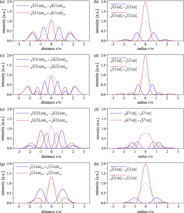
Figure 2. Intensity distribution of different mode combinations in Cartesian (left) and cylindrical (right) geometry at the position of the obstacle (blue) and at a different position (red), where the contributing modes are added with a different sign. This is the position of maximal intensity for (a)–(d) and (g)–(h), or the position of minimal slit width (e) or hole radius (f). Panels (g) and (h) show a mode combination in an imaging resonator with ψE = π, rather than a quasi-imaging resonator. The intensity of the reference fundamental mode with the same q-parameter and power is shown in (a)–(d) and (g)–(h) as a gray dashed line. In (e) and (f) the simple modes GH1,0 and GL20 are shown as gray dashed lines, respectively. The blue dotted line shows the far-field distribution of the field at the position of the obstacle (blue) for the case that a phase mask is used, with steps of π to set the four lobes to equal phase (e) or sinusoidal around the optical axis with π exp(I 2φ) (f). The transverse coordinates x and r are normalized to the radius w of the fundamental mode. For the cylindrical geometry the distribution is extended to negative radii for a clear depiction. The indicated coefficients for the mode combinations hold, if the modes are normalized to unity power content.
Download figure:
Standard image High-resolution imageFor ψE = π/3 or 5π/3 it is Δn = 6 and Δp = 3 and the mode combinations are GH0,0 & GH6,0 and GL00 & GL03 (figures 2(c), (d)). For ψE = 2π/3 or 4π/3 it is Δn = 3, however, the GH3,0 mode is odd and cannot yield zero on the optical axis in combination with the fundamental mode. For the sake of completeness, note that in the case of an imaging resonator with ψE = 0 or π all respectively all even/odd modes are simultaneously resonant and the simplest mode combinations avoiding an on-axis obstacle are GH0,0 & GH2,0 and GL00 & GL01 (figures 2(g), (h)). The difference between an imaging resonator and a quasi-imaging stable resonator will be discussed in more detail in section 7.
The mode combinations yield zero intensity on the optical axis at the position of the obstacle. Upon propagation in the resonator the modes acquire a different phase, so that the on-axis intensity of the mode combination oscillates between zero and a value Imax. For two combined transverse modes GHn1,m(x,y), GHn2,m(x,y) with coefficients c1, c2 the on-axis intensity is I(z) = P|c1GHn1,m(0,0) exp(i(n1 + ½)ψx(z)) + c2GHn1,m(0,0) exp(i(n2 + ½)ψx(z))|2. With c1 GHn1,m(0,0) = –c2 GHn2,m(0,0) by construction and c12 + c22 = 1, this yields I(z) = Imaxsin2((Δn/2)ψx(z)) with Imax = 4P|c1 GHn1,m(0)|2 = 4P|c2 GHn2,m(0)|2, assuming m even. The on-axis intensity is I(z) = Imax sin2(Δp ψr(z)) in the case of cylindrical symmetry. The intensity course changes if additional transverse modes are involved. For the case that the obstacle is a hole or slit in a focusing mirror behind a resonator-internal focus, the on-axis intensity in the focal plane is maximal for the case ψE = π/3 and is zero for the case ψE = π/2. In the latter case, the on-axis intensity is maximal one Rayleigh length before and behind the focus. This follows from (4), which yields ψ = π/4 for propagating the distance zR from the waist position and ψ ≈ π/2 for propagating many Rayleigh lengths to the focusing mirror.
Single GHn,m modes with odd order n or m and GLlp modes with azimuth mode order l > 0 exhibit zero intensity on the optical axis and can avoid a small on-axis obstacle (as demonstrated for GH1,0 in [22]). However, the width of the intensity minimum can be enlarged by combination with suitable additional modes. Two simple cases in Cartesian and cylindrical geometry, respectively, are the combination of GH1,0 & GH5,0 and of GL20 & GL22 (figures 2(e), (f)). If an on-axis maximum of the field distribution in the focus is desired, phase masks can be applied (figure 2) as suggested in [22]. In order to minimize loss due to the phase masks, the second phase mask should be in the image plane of the first. This is only approximately given for the two focusing mirrors of a bow-tie resonator in the middle of the stability range (section 4). Therefore, the first phase mask should be on a plane mirror before the first focusing mirror and the second one on the focusing mirror with a slit or hole following the focus.
3.2. Properties of the hole modes and slit modes
The diffraction loss due to an obstacle can be estimated by the following consideration. The power transmission for a normalized field u at the position of an obstacle is T = ∫∫Ω dξ|u|2, with the integration area Ω omitting the obstacle. Note that T is the power reflection if the obstacle is a slit of hole in a mirror. The normalized truncated field then is uT = u/T1/2 in Ω and 0 elsewhere. The spatial overlap Uobstacle of this truncated field with the original field is
Therefore, the same loss as at the obstacle can be expected at the propagation of the truncated field, and the diffraction loss per resonator round trip is estimated to be 1 − T2. This assumes that the part of the truncated field not overlapping with the original field is lost at the resonator round trip, which is not necessarily true in particular in the case of transverse mode degeneracy. A rigorous model is given in section 6. For a non-degenerate resonator this is expected to be a very good estimation, which has been validated in [23]. In order to damp the part of the circulating field that is diffracted into higher order modes at the obstacle, appropriate apertures can be included in the resonator. The correspondingly estimated round trip loss is shown for different modes as a function of the obstacle size in figure 3. The calculation suggests that for eigen-modes of a quasi-imaging resonator compared to simple GH or GL modes, a much broader slit or hole is possible at small loss.
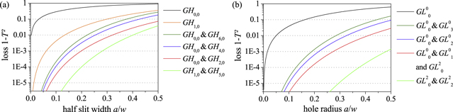
Figure 3. Diffraction loss of GH and GL modes and mode combinations as a function of the size of the obstacle for Cartesian (a) and cylindrical (b) geometry. w is the Gaussian beam radius at the position of the obstacle. The loss for GH modes and mode combinations at a hole is smaller than at a slit and is not indicated here.
Download figure:
Standard image High-resolution imageBesides the spatial overlap Uobstacle describing the diffraction loss at the obstacle, another spatial overlap has to be introduced: The spatial overlap UIC of the circulating field ucirc in the resonator (mode or mode combination) and the impinging field uin (typically a Gaussian beam), which indicates the spatial overlap at the input coupling mirror of an enhancement resonator (section 5)
An incomplete overlap proportionally diminishes the power enhancement.
Table 1 summarizes some properties of different GH and GL modes and mode combinations.
Table 1. Properties of different modes and mode combinations. Spatial overlap UIC (qE) of the circulating field with an impinging Gaussian beam with the same q-parameter and spatial overlap UIC (qmax) with a Gaussian beam with the q-parameter adapted for maximal overlap. The values in parentheses hold if a phase mask is used (step of π on the optical axis for GH1,0 and GH1,0 & GH5,0, sinusoidal around the optical axis for GL20 and GL20 & GL22). Hole radius or half slit width a divided by the Gaussian beam radius w for a loss of 1% and 0.1%, allowing for a power enhancement of 100 and 1000 (with negligible other losses and impedance matched) referred to the spatially and spectrally overlapping part of the incident beam. The loss is estimated by the square of the transmission T through the obstacle. Power P0 in central lobe, maximal intensity I0 in central lobe; distance x1 from the optical axis to the intensity maximum at the obstacle, power P1 in ring around the hole or in the two lobes next to the slit, maximal intensity I1 in the ring around the hole or in the lobes next to the slit. The power is indicated relative to the total power P, the intensity relative to the on-axis intensity of the fundamental mode I = 2P/(πw2) at the same longitudinal position.
| Geometry | Cartesian | Cylindrical | ||||||||||
|---|---|---|---|---|---|---|---|---|---|---|---|---|
| Gouy parameter ψE |

|
π/2 |

|

|

|
π/2 |

|

|
||||
| GL/GH mode or mode combination |

|

|
 & & 
|
 & & 
|
 & & 
|
 & & 
|

|

|
 & & 
|
 & & 
|
 & & 
|
 & & 
|
| Overlap UIC (qE) | 1 | 0 | 0.333 | 0.273 | 0 | 0.238 | 1 | 0 | 0.500 | 0.500 | 0 | 0.500 |
| Overlap UIC (qmax) | 1 | (0.827) | 0.690 | 0.442 | (0.819) | 0.328 | 1 | (0.844) | 0.844 | 0.593 | (0.559) | 0.500 |
| a/w for T2 = 0.99 | 0.003 | 0.134 | 0.321 | 0.254 | 0.403 | 0.222 | 0.050 | 0.411 | 0.411 | 0.326 | 0.626 | 0.285 |
| a/w for T2 = 0.999 | 0.0003 | 0.062 | 0.199 | 0.157 | 0.282 | 0.137 | 0.016 | 0.274 | 0.274 | 0.217 | 0.481 | 0.190 |
| At the position of the maximal on-axis intensity: field in the central lobe | ||||||||||||
| Power P0/P | 1 | — | 0.704 | 0.449 | — | 0.332 | 1 | — | 0.865 | 0.594 | — | 0.463 |
| Intensity I0/I | 1 | — | 1.333 | 1.091 | — | 0.952 | 1 | — | 2 | 2 | — | 2 |
| At the position of the obstacle: field in a ring around the hole or in the two lobes next to the slit | ||||||||||||
| Distance x1/w | — | 0.707 | 1 | 0.707 | 0.959 | 0.590 | — | 1 | 1 | 0.765 | 1.199 | 0.656 |
| Power P1/P | — | 1 | 1 | 0.588 | 0.861 | 0.473 | — | 1 | 1 | 0.762 | 0.966 | 0.689 |
| Intensity I1/I | — | 0.736 | 0.722 | 0.713 | 0.916 | 0.693 | — | 0.271 | 0.271 | 0.425 | 0.301 | 0.335 |
3.3. Higher-order slit modes
The discussed mode combinations of two GH or GL modes are eigen-modes of a resonator in which these modes are simultaneously resonant and with an obstacle on the optical axis which is sufficiently small so that the diffraction loss is small. By adding higher-order resonant GH or GL modes, further eigen-modes of the quasi-imaging resonator can be constructed. For a quasi-imaging resonator with mode number difference Δn = 4, the simplest slit mode containing the fundamental mode is
We therefore call it 'simple slit mode'. Another slit mode, that also vanishes on the optical axis and is orthogonal to the first, can be constructed by adding the next resonant mode GH8,0
Another slit mode, orthogonal to the two others is
These eigen-modes of a quasi-imaging resonator are visualized in figures 4(a), (b). The contribution of the higher-order slit modes to the circulating field changes the spatial overlap with the impinging field distribution and the width and depth of sharpness of the intensity minimum. Higher order slit modes are transversally more expanded and more sensitive to loss at additional apertures limiting the transverse extent of the field distribution. They change their shape at propagation more rapidly, because GH modes of higher order are involved.
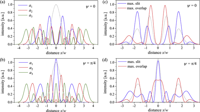
Figure 4. Intensity distribution of the three lowest order slit modes a1, a2, a3 including GH0,0 of a quasi-imaging resonator with mode number difference Δn = 4 at the position of the obstacle (a) and after propagation with a Gouy phase of ψ = π/4 (b). The fundamental mode is shown as a gray dashed line. Simple slit mode a1 with a contribution of next order slit mode a = (1−|c2|2)1/2 a1 + c2 a2 for maximal slit width (c2 = −0.535) and for maximal overlap with a Gaussian beam with the same q-parameter (c2 = 0.554), at the position of the obstacle (c) and after propagation with a Gouy phase of ψ = π/4 (d). The simple slit mode is shown as a gray dashed line. The overlap is increased to UIC = 0.39 compared to UIC = 0.27 for the simple slit mode a1. The overlap at maximal slit width is UIC = 0.07.
Download figure:
Standard image High-resolution imageFigures 4(c), (d) shows the simple slit mode a1 complemented with a contribution of a2 that yields a maximal slit width (vanishing d2E/dx2| x × 0) and a maximal overlap with a Gaussian beam with the same q-parameter. It is descriptive that these two conditions are opponent, because the field of the Gaussian beam is maximal on the optical axis.
4. Quasi-imaging ring resonator
4.1. Symmetric bow-tie resonator
A common and simple resonator design for an enhancement resonator is a (symmetric) bow-tie ring resonator with two curved focusing mirrors with radius of curvature RC and resonator length L (figure 5) [4, 5, 7, 8, 22, 23, 28, 36]. Confined by the curved mirrors this resonator has a long arm and a short arm with a small beam waist and a distance of the curved mirrors d. For a constant resonator length (e.g. determined by the repetition rate of the impinging fs pulse train), the resonator is stable for the range of the distance of the curved mirrors d1 < d < d2. The Gouy parameter of the resonator is
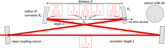
Figure 5. Quasi-imaging ring resonator. In the middle of the stability range the Gouy parameter ψE,x in the sagittal transverse direction (orthogonal to the plane of the beam path) is ψE,x = 3π/2 and the modes GH0,0 and GH4,0 are simultaneously resonant. The Gouy phase acquired in the short arm is ψx ≈ π and in the long arm ψx ≈ π/2. The intensity distribution of the simple slit mode in the transverse direction of the quasi-imaging is shown at selected positions. The slit allows for a geometrical access to the optical axis, which could be used for output coupling of high harmonics generated in a gas jet near the focus (path of the harmonics indicated by a blue arrow in the sketch). The output coupling mirror with the slit is also shown in top view.
Download figure:
Standard image High-resolution imageQuasi-imaging with Gouy parameter ψE = 3π/2 is achieved in the middle of the stability range for d = dm.
With this condition met (d = dm), there are only two design parameters of the resonator, L and RC. The Rayleigh lengths zR in the short (+) and in the long (–) arm are
The beam waist radius in the short arm is w0, which is in first approximation proportional to RC. In order to achieve a desired beam waist radius, the radius of curvature RC has to be chosen such that:
with wavelength λ. The beam radius on the curved mirrors is
i.e. the beam cross section is in first approximation proportional to the resonator length and independent of the radius of curvature. A detuning δψ from quasi-imaging (ψE = 3π/2) in terms of the Gouy parameter ψE is given by a detuning δ d in terms of the distance d by
For the design of an enhancement resonator for nonlinear processes the ratio of the maximal intensity at the focus and on the focusing mirrors is of importance, because the latter is limited by damage thresholds. For the simple slit mode with Δn = 4 this ratio is the same as for the fundamental mode with the same q-parameter. The intensity can be a factor 1.5 larger on a mirror in the long arm of a bow-tie resonator (if located in the middle of the long arm).
4.2. Astigmatism in the bow-tie resonator
The discussion in this section did so far not include the angle of incidence α on the curved mirrors. This angle leads to an effective radius of curvature of the focusing mirrors RC,t = RC cos(α) and RC,s = RC /cos(α) in tangential (i.e. plane of beam path) and the sagittal transverse direction, respectively. This leads to an ellipticity of the resonator eigen-mode and a different Gouy parameter for the two transverse directions. Even though the resulting ellipticity = w0,s/w0,t in the beam waist is small for a small angle of incidence ( ≈ 1 + α2 in the short arm and ≈ 1 + (L/RC − 1) α2 in the long arm for the middle of the stability range), the difference in the Gouy parameter ΔψE = ψE,s − ψE,t ≈ 2(L/RC − 1) α2 is significant in a high-finesse resonator. The degeneracy of transverse modes with the same sum of the two transverse mode order numbers n + m = const. is lifted and the resonances of these modes can be clearly distinguished [7]. Therefore, quasi-imaging can in this setup possibly be achieved only in one transverse direction. In the other direction, the field distribution is that of the fundamental mode (or another single transverse mode). If quasi-imaging is adjusted in the sagittal instead of tangential direction, the angle of incidence can be smaller, because the field is transversally more expanded in the direction of quasi-imaging. Figure 5 shows a sketch of such a quasi-imaging ring resonator. The discussions in the following sections refer to this situation.
The degeneracy of the transverse modes with n + m = const can be restored, i.e. the Gouy parameters in the transverse directions can be matched, by different means. Further astigmatic elements like a plate at Brewster's angle can be introduced into the resonator. This, however, introduces dispersion and nonlinearity. Off-axis parabolic mirrors can be used instead of spherical mirrors, avoiding the astigmatism. Moreover, a defocusing mirror in the long arm close to a focusing mirror allows for matching the Gouy parameters in the transverse directions, if the angle of incidence is properly chosen. However, all these setups go along with increased alignment sensitivity. Undoubtedly, a resonator with quasi-imaging in both directions has potential advantages: the hole mode allows for a larger opening, exhibits a larger overlap with an impinging Gaussian beam and a larger power fraction in the central lobe compared to the slit mode (table 1). But then, also e.g. the accessibility of the intensity lobes for a gas nozzle for HHG has to be considered. This is better provided for a slit mode, with a Gaussian intensity distribution in tangential direction. Moreover, the alignment of the resonator axis to a slit in a mirror is crucial only in one direction.
5. Mode matching of the impinging beam
For the eigen-modes of a quasi-imaging resonator containing the fundamental mode (section 3) the spatial overlap with an impinging Gaussian beam with the resonator eigen-q-parameter can be calculated from the coefficients of the contributing GH or GL modes. These coefficients are determined by the condition of a vanishing on-axis field at the obstacle (figure 2). Because the on-axis field amplitude of normalized GL0p modes is independent of the mode order p, the modes have to be combined with equal magnitude to yield zero on the optical axis. Thus, the overlap with the fundamental mode is UIC = 1/2. The on-axis field amplitude for even GHn,0 modes decreases with mode order n. Therefore, the overlap with the fundamental mode is smaller, e.g. UIC = 3/11 for the combination of GH0,0 and GH4,0 (see table 1).
The spatial overlap with an impinging Gaussian beam can be increased by choosing an adapted q-parameter, i.e. adapted z0 and zR, or equivalently Gaussian beam radius w and radius of curvature of the phase front. The overlap between two modes (9) does not change at propagation, i.e. it is independent of the position in z-direction of the plane where it is evaluated. We choose the position of maximal on-axis intensity, to find the q-parameter of the Gaussian beam with maximal overlap with the simple slit mode (GH0,0 & GH4,0). At this position (not at other positions) the overlap is maximal if the phase front curvature of the Gaussian beam is the same as for the circulating field. The overlap as a function of the beam radius in the direction of quasi-imaging is UIC,x = (24/11)χ(χ4 + 1)2/(χ2 + 1)5 for the simple slit mode with χ = wx,in/wx,circ. This function has maxima at a smaller and a larger beam radius with a maximal overlap of UIC = 0.44, which is 1.6 times larger than the UIC = 0.27 for the eigen-q-parameter (figure 6(a)). This can be understood from figure 6(b). The Gaussian beam with the eigen-q-parameter (win = wcirc) overlaps with the central lobe of the slit mode and with the adjacent lobes with opposite sign. The overlap is maximal if either the Gaussian beam overlaps with the central lobe alone (win = 0.36 wcirc) or it also overlaps with the outer lobes which again have the same sign as the central lobe (win = 2.8 wcirc). Changing the incident beam radius decreases the overlap in the perpendicular direction with Gaussian field distribution according to UIC,y = 2η/(η2 + 1) with η = wy,in/wy,circ (figure 6(a)). For maximal overlap, the beam radius of the impinging beam has to be adapted independently in the transverse directions, e.g. using cylindrical lenses.
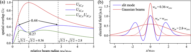
Figure 6. (a) Overlap of the simple slit mode of GH0,0 and GH4,0 with a Gaussian beam as a function of beam radius. (b) Field distribution of the slit mode at the position of maximal intensity on the optical axis and the two Gaussian beams with maximal overlap (assuming the same radius of curvature of the phase front).
Download figure:
Standard image High-resolution imagePhase masks can be used to adapt the impinging beam by imposing phase shifts of π to selected spatial regions. This is particularly effective, if odd field distributions like GH1,0 [22] or the slit mode of GH1,0 & GH5,0 are considered (table 1). By the contribution of higher-order slit modes to the circulating field the spatial overlap can increase (figure 4(b)). Theoretically, the overlap can reach unity if the impinging beam is adequately shaped (in amplitude and phase). This could e.g. be achieved with free form optics or two phase plates.
6. Modelling of quasi-imaging enhancement resonators
6.1. Mode expansion model
This section introduces an analytical model based on mode expansion of the circulating field, which allows for describing the sensitivity against detuning from the degeneracy and against aberrations. The sensitivity against detuning is of crucial importance for the experimental implementation of a quasi-imaging resonator. These calculations can just as well be done by using the method of Fox and Li [10], which gives the same results. However, by the mode expansion the prominence of the Gouy parameter and the transverse modes is more obvious.
In section 3 an orthogonal set of slit modes is introduced (10)–(12), which allows for describing the field distribution in a quasi-imaging resonator. These slit modes assume that all contributing GH modes are simultaneously resonant. In order to model the performance of the resonator for a detuning from degeneracy, a different approach has to be chosen. The circulating field can be expanded by the GH modes, which are close to resonance. This is a limitation of generality only in so far, as non-resonant modes are neglected. If several GH modes propagating independently in the resonator have to be simultaneously enhanced, their round-trip phase difference Δn δψ determined by the mode number difference Δn and the detuning δψ against degeneracy has to be smaller than the width of the resonance curve. The resonance curve for a GH mode in a resonator with Finesse F = 2π/(1 − RICR) is P(ϕ) = (1 − RIC)/(1 + RICR − 2(RICR)1/2cos(ϕ)) with the power loss factor R of the resonator, the input coupler reflectivity RIC and the round-trip phase ϕ (figure 7(a)). The full width at half maximum of this curve is Δϕ = 2π/F. If in a resonator there is only loss acting evenly on the amplitude of the electric field (like the reflectivity of mirrors), the transverse modes propagate independently in the resonator. An impinging beam will be projected on the orthogonal set of GH modes, which will be enhanced (or suppressed) differently depending on their round trip phase ϕ [20, 24]. If two modes with mode number difference Δn and with their resonances shifted due to a detuning δψ against the degeneracy should be equally enhanced, both modes have to be off resonance by half the phase difference Δn δψ/2. The power enhancement of this mode combination as a function of the detuning then is
with the spatial overlap UIC. The width of this detuning curve is Δψ = (2/Δn)(2π/F). This situation is depicted in figure 7(b).

Figure 7. (a) Derivation of the resonance curve P(ϕ) in an enhancement resonator from the postulation of a stationary solution [25]. (b) Resonance curves for two transverse resonator modes with mode number difference Δn, which are shifted against each other by a detuning δψ against degeneracy.
Download figure:
Standard image High-resolution imageIf an obstacle is placed in the resonator the GH modes are coupled at the obstacle. The above-mentioned consideration is no longer valid and the detuning curve P(δψ) becomes broader. The projection of one GH mode onto another is non-zero if the field is set to zero on a part of the integration area due to an obstacle. This shall be discussed for the quasi-imaging resonator with the modes GH0,0, GH4,0 and GH8,0. In this model the field is described by the expansion for GH modes (which are not eigen-modes of the resonator with the obstacle), because for these modes the Gouy phase is well-defined as a phase additionally acquired on the optical axis according to the Gouy parameter of the resonator. The circulating field is described by the complex coefficients c0, c4, c8 for the (normalized) modes, which are abbreviated by u0, u4, u8. The coupling between the modes is described by a matrix T with elements tj,l = 2∫x = a..A uj(x) ul*(x) dx, j, l = 0, 4, 8 [26]. Here a is the half width of the slit and A the distance from the optical axis of an additional aperture, which can be applied to restrict contributions of mode u8 or higher. T is real and symmetric for GH modes with the same q-parameter. T is the identity matrix for a vanishing obstacle and aperture, but in the presence of an obstacle, the diagonal elements are smaller than unity and the non-diagonal elements differ from zero. By this coupling a power transfer between the modes occurs. This is necessary for instance, if the impinging beam overlaps with the fundamental mode u0 alone, the circulating field, however, is composed of u0 and u4 in order to minimize the loss at a slit. The modes acquire a different phase at a round trip due to a detuning δψ against degeneracy according to the mode order, ψl,l = exp(i l δψ), l = 0, 4, 8. The coefficients describing the circulating field cl for an impinging field bl can be determined from the postulation of a stationary solution [11, 22]
The round trip is described by the coupling T at the slit (and aperture), the phase δψ imprinted due to detuning, the amplitude loss factor r and the reflection at the input coupler with reflection coefficient rIC. The matrix S (given below) accounts for potential aberrations at the focusing mirrors. The input coupling is given by the overlap of the impinging beam uin with the resonator modes bl = ∫ul(x) uin*(x) dx, l = 0, 4, 8 and the transmission through the input coupler with transmission coefficient tIC =  . The round trip phase ϕ is chosen for maximal power enhancement P = Pcirc/Pin = Σl|cl|2. This derivation is analogous to the derivation of the resonance curve in figure 7(a), which is valid for a single resonator mode.
6.2. Aberrations of the enhancement resonator
Wave-front aberrations in an enhancement resonator can limit the enhancement. This limitation is considerably more severe in case of a circulating slit mode or hole mode compared to the fundamental mode due to their larger transverse extent. The reflection on a curved mirror (radius of curvature RC) placed under an angle of incidence α yields astigmatism, spherical aberration, coma and further aberration terms. Astigmatism, i.e. different effective radii of curvature in the two transverse directions, does not represent an aberration in this context, because it does not yield a deviation from a Gaussian beam but only produces different eigen-parameters for the transverse directions (section 4). Aberrations, i.e. deviations from a parabolic wave front, have basically two effects: a coupling between transverse modes and different phase shifts for the transverse modes. The latter effect can be relevant even if the coupling between the transverse modes is weak. From the additional mode-dependent phase shift it follows that not all modes of a degeneracy (in our case u0, u4, u8...) are resonant for exactly the same Gouy parameter. Therefore, the detuning curve can show multiple maxima with different modes being simultaneously resonant. The effect of the aberration on the field in the resonator is described by a matrix S with elements
Here Δϕ (x, y) is the difference between the imprinted phase at reflection from the mirror and a parabolic phase, suitably chosen to remove a focusing effect or tilt, thereby considering the net aberration. As criterion for the proper removal of focusing and tilt we minimize the rms wave-front difference weighted with the intensity profile of the fundamental mode u0, which is equivalent to maximizing |s0,0|. Moreover, an offset Δϕ (0, 0) is chosen to yield zero phase shift for the fundamental mode.
For spherical aberrations alone (vanishing angle of incidence α) the phase difference at reflection on a mirror taking into account terms up to the fourth order is Δϕ (r) = −Δϕw (r4/w4 − 2r2/w2 + 1/2), where the parameter Δϕw = kw4/(4RC3) with the Gaussian beam radius w on the mirror indicates the strength of the aberration. With (16) and (17) it follows Δϕw ≈ (1/16) (λ/π)5/2L1/2/w03. This means that the strength of the aberration Δϕw strongly depends on the beam waist radius w0. Expanding the phase shift imprinted due to spherical aberration in Δϕw we find in first approximation arg(s0,0) = 0, arg(s4,4) = (9/2) Δϕw and arg(s8,8) = 21Δϕw. A finite angle of incidence α additionally leads to coma, which adds to the phase shift. The phase shift increases by a factor 1/(1 − α2)3/2 for transverse modes in sagittal direction and by a factor (1 + 4α2)/(1 − α2)7/2 for transverse modes in tangential direction. That is, the effect is stronger in tangential direction.
The absolute values of the matrix elements describe the coupling strength and loss due to the aberration. For vanishing angle of incidence they are in first approximation given by |s0,0| = 1 − (1/8) Δϕw2, |s4,4| = 1 − (689/32) Δϕw2 and |s8,8| = 1 − (4413/16) Δϕw2. Again, coma adds to the deviation from unity and this increase is stronger for transverse modes in tangential direction compared to the sagittal direction. For small angles of incidence the effect of coma is small and it will be neglected in the following.
Estimating |sl,l| as a loss factor for mode ul, the loss for u4 is considerably greater than for the fundamental mode u0 (the factor being 170), as can be expected from the greater transverse extent. The limitation of the finesse due to spherical aberration for a quasi-imaging resonator is therefore considerably more critical than for operation in the fundamental mode.
Besides the aberrations of spherical surfaces also the deformation of surfaces can produce aberrations and lead to a coupling of transverse modes. This can be surface roughness [27], thermally induced deformations [28] or surface deformations caused by the processing of holes or slits [29].
6.3. Comparison with previous experiments
Figure 8 shows the calculated power enhancement as a function of detuning from quasi-imaging together with experimental data, which are taken from [7]. Model and measurement are in excellent agreement. The finesse at the maximum of the curve is F = 3000, power enhancement is limited by the spatial overlap of UIC = 0.27 of the impinging Gaussian beam with the circulating simple slit mode. Also the detuning curve according to (19) is drawn in figure 8, showing that the coupling of the modes at the obstacle leads to a significant broader detuning curve. It is sufficiently broad that it does not demand for an active control. Then again, this is only a small fraction of the stability range of d2 − d1 = 3.2 mm.
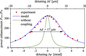
Figure 8. Power enhancement Pcirc/Pin versus detuning from the resonator degeneracy with half slit width a/w = 0.05 and an additional aperture at a distance from the optical axis of A/w = 2.9. The parameters are: input coupler reflectivity RIC = 0.9986, loss factor R = 0.99953, spherical aberration Δϕw = 0.678 mrad per focusing mirror, impinging Gaussian beam with eigen-q-parameter (b0 = 1, b4 = b8 = 0). The experimental data are taken from [7]. The resonator length is L = 3840 mm, the radius of curvature of the focusing mirrors RC = 150 mm and the wavelength λ = 1040 nm.
Download figure:
Standard image High-resolution imageIn the experiment [7] an aperture was used to suppress contributions of transverse modes higher than u4. A distance of the aperture of A = 2.9 w from the resonator axis is sufficient to damp mode u8 and higher, and does not introduce significant loss to u0 and u4. Figure 9 shows results of a calculation with the same parameters as in figure 8, contrasting the situation with and without the aperture. With the aperture omitted, higher-order transverse modes can contribute to the circulating field. These contributions appear at a position in the stability range which is detuned compared to the degeneracy of the modes u0 and u4 (δψ = 0), thereby compensating for the greater phase which these modes acquire due to spherical aberration. They lead to a structured detuning curve with maxima and minima (figure 9(c)). For a given detuning there can be more than one maximum of the enhancement at varied round-trip phase, corresponding to different field distributions. The simulation yields three distinguished areas of high enhancement in a space spanned by detuning δψ and round-trip phase ϕ (figure 9(a)). This follows from the inclusion of the modes u0, u4, u8, u12 in the simulation, which can be combined to the three slit modes a1, a2, a3 (10)−(12). By inserting the aperture the contributions of higher transverse modes can be reduced to only a small portion (figure 9(d)).
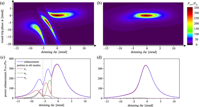
Figure 9. Power enhancement Pcirc/Pin as a function of detuning δψ from the resonator degeneracy and round-trip phase ϕ, without (a) and with (b) an aperture at a distance from the optical axis of A/w = 2.9, and corresponding detuning curve without (c) and with (d) the aperture. The aperture is at the same longitudinal position as the slit. The detuning curve is the enhancement versus detuning, with the round-trip phase chosen for maximal enhancement. The points where this phase makes a jump are marked with a gray dashed line. Also the portion of the power in the different slit modes is shown. The parameters are: half slit width a/w = 0.05, input coupler reflectivity RIC = 0.9986, loss factor R = 0.99953, spherical aberration Δϕw = 0.678 mrad per focusing mirror, impinging Gaussian beam with eigen-q-parameter (b0 = 1, b4 = b8 = b12 = 0).
Download figure:
Standard image High-resolution image6.4. Scope of the simple slit mode
We performed calculations to investigate, which half slit width a related to the beam radius w at the position of the slit can be tolerated to allow for a desired enhancement of the simple slit mode. We assume the impinging beam to be shaped for complete spatial overlap with the simple slit mode. To show the qualitative effects, a round-trip loss factor R = 0.999 is assumed, which accounts for the imperfect reflectivity of the resonator mirrors. Spherical aberration of Δϕw = 0.5 mrad per focusing mirror are assumed (as a reasonable value for a bow-tie enhancement resonator). An aperture suppresses contributions of higher transverse modes. Figure 10(a) shows the calculated power enhancement Pcirc/Pin versus slit width for different input coupler reflectivities RIC. The inlay of figure 10(a) shows the spatial overlap of the circulating field with the simple slit mode, which is close to unity in a large range of slit widths.
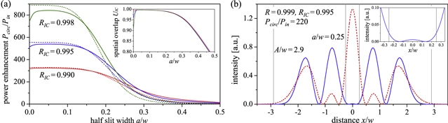
Figure 10. (a) Calculated power enhancement Pcirc/Pin versus half slit width a/w for different input coupler reflectivities RIC, calculated with the mode expansion model according to (20) (solid lines) and with a simple loss estimation (dashed lines, see text for details). The modes u0, u4, u8 are included in the calculation. The impinging field is the simple slit mode (b0 = (3/11)1/2, b4 = (8/11)1/2, b8 = 0). A round-trip loss of R = 0.999, spherical aberration of Δϕw = 0.5 mrad per focusing mirror and an aperture at a distance from the resonator axis A = 2.9w and at the same position as the slit are assumed. The inlay shows the spatial overlap UIC of the circulating field with the simple slit mode versus the half slit width a/w. (b) The intensity profile of circulating field at the position at the slit (blue solid line) and after propagation with a Gouy phase of ψ = π/4 (red dashed line) for an exemplary situation with input coupler reflectivity RIC = 0.995 and half slit width a/w = 0.25, allowing for a power enhancement of Pcirc/Pin = 220.
Download figure:
Standard image High-resolution imageFor very broad slits, the circulating field arranges in a way which yields a decreasing overlap with the slit mode. Surprisingly, also for very small slits the spatial overlap decreases, therefore deviating from the impinging field distribution, and also the enhancement is smaller compared to a half slit width of a/w ∼ 0.05. This is due to the spherical aberration, which lets the contributing modes u0 and u4 run out of phase. A finite slit width with a stronger coupling between these modes helps to avoid this. Also included in figure 10(a) (dashed lines) is the simple calculation of the enhancement according to P(a/w) = (1 − RIC)/(1 − (RIC R T(a/w))1/2)2 with the loss due to the slit estimated by the power transmission T(a/w) of the simple slit mode with Gaussian beam diameter 2w through the obstacle with width 2a (section 3). The estimation of the loss by squaring this loss factor in order to account for the diffraction loss at propagation (which is valid in a non-degenerate resonator) leads to an overestimated loss here. The circulating field in the degenerate resonator can arrange to minimize loss, which includes small contributions of higher transverse modes despite the aperture and does not imply that the field vanishes completely on the resonator axis (as assumed for the simple slit mode). For a broad slit the intensity at the edge of the slit can be reduced at the expense of a non-vanishing intensity on-axis. Therefore, the enhancement for broad slits is larger than calculated with this simple loss estimation. Figure 10(b) shows the intensity profile at the position of the slit for an exemplary situation, which is close to impedance-matched and allows for an enhancement of Pcirc/Pin = 220 at a half slit width of a/w = 0.25. It can be seen from the inlay of figure 10(b), that the intensity is not exactly zero on the resonator axis. The contribution of u8 is |c8|2/Pcirc = 0.01 and the spatial overlap of the circulating field with the simple slit mode is UIC = 0.98. The width of the detuning curve is Δψ = 25 mrad. 0.16% of the circulating power (35% of the incident power) is transmitted through the slit. The gray lines indicate the position of the slit and the aperture. Significantly broader slits at a large enhancement are possible if large contributions of higher transverse modes are allowed (compare figure 4(c)).
7. Imaging resonator
An imaging resonator is understood to reproduce an arbitrary field distribution after a resonator round trip without diffraction losses. This is achieved by telecentric imaging with magnification ±1, i.e. the beam transfer matrix being the positive or negative identity matrix. Such a resonator with A + D = ±2 does obviously not satisfy the stability condition |A + D| < 2 (1), and is not stable in the sense that there is no well-defined eigen-q-parameter (2). Rather, any q-parameter is reproduced. However, a q-parameter can be distinguished as a continuation of the eigen-q-parameter at approaching the imaging point in the stability diagram. The simplest setup of an imaging resonator is the symmetrical confocal resonator with the resonator length L equal to the radius of curvature RC. Here, the q-parameter with Rayleigh length equal to half the resonator length zR = L/2 is distinguished as the continuation of the eigen-q-parameter for larger or smaller resonator lengths (for constant RC). The imaging point L = RC is therefore solely adjacent to stable regions (0 < L < RC and RC < L < 2RC). However, this only holds if symmetry is assumed (equal radius of curvature of the two resonator mirrors). With this assumption dropped, the imaging point is adjacent to stable as well as instable regions, and it can therefore be considered at the border of the stability range.
An imaging resonator with magnification +1 (also called totally degenerate) [24, 30] does not act as a transverse mode filter, because all transverse modes are simultaneously resonant. An arbitrary transverse field distribution is enhanced, i.e. the circulating field is determined by the impinging field alone. This means, that the optical axis and the position and size of the beam waist are not determined by the resonator. In an imaging resonator with magnification −1 there is also no distinguished eigen-q-parameter. However, there is an optical axis determined by the resonator. The circulating field will be constantly even or odd with respect to this axis, even if the impinging beam is tilted or displaced. Still the size and longitudinal position of the beam waist is determined by the impinging field only. In a quasi-imaging resonator in addition to the optical axis there is also a well-defined eigen-q-parameter and the field is restricted to combinations of just a subset of GH modes with this q-parameter. Only in a resonator without transverse mode degeneracy the circulating field distribution is completely determined by the resonator, i.e. independent of the impinging field distribution (and its fluctuations). It is discussed in section 7 and demonstrated in [7], that by employment of apertures the field can e.g. be restricted to GH0,0 and GH4,0 with only a small contribution of GH8,0. Of course, also in an imaging resonator the field can be determined by apertures, as demonstrated in [31].
While quasi-imaging can be achieved in a stable resonator, this is not true for imaging. Imaging cannot be achieved in a standard bow-tie ring resonator without adding further curved mirrors. This leads to additional distances which have to be adjusted, in order to reach the imaging point in the stability diagram, which is furthermore adjacent to instable regions. This is distinctly more elaborate than adjusting for quasi-imaging with a single parameter, namely the distance d of the curved mirrors, which can be easily read from the resonances in a scan pattern [7].
8. Further discussion
8.1. Resonator-assisted HHG
The on-axis access to a high-finesse resonator can be used for output coupling of high harmonics generated in a gas jet near the focus. We recently demonstrated the suitability of the field distribution for efficient high-order harmonic generation, achieving an output-coupled power of 11 μW at 61 nm (17th harmonic) [8]. Figure 11 shows the intensity and phase distribution of the simple slit mode around the beam waist. Because the slit mode changes its shape rapidly around the focal plane (see also figure 5) the intensity course is steeper than for the fundamental mode at equal Rayleigh length. The slit mode exhibits on-axis lobes around one Rayleigh length before and behind the focus and two central lobes in the focal plane. The lobes in the focal plane contain 0.59 of the power and exhibit a plane wave front with a slope of the phase dϕ/dz = 3/zR, which is three times larger than for the fundamental mode with the same q-parameter (figure 11(c)). The two lobes are in phase, which means that the harmonic signal will exhibit a maximum on the optical axis in the far field, which can pass through a slit [8]. The on-axis intensity is maximal at a distance ±zR/21/2 from the focal plane. This maximum is closer to the focus than one Rayleigh length where the contributing modes interfere constructively on-axis (compare figure 2(a)), because the beam cross section increases with distance from the focus. The central lobe resembles a Gaussian profile with radius w = 0.53·w0 containing 0.42 of the power. The curvature of the intensity course in propagation direction is with −½ (d2I /dz2) (1/I0) = 5/zR2 larger than for the fundamental mode in the focal plane with −½ (d2I /dz2) (1/I0) = 1/zR2 (figure 11(a)). The slope of the phase is dϕ/dz = 2/zR, which is two times larger than for the fundamental mode with the same q-parameter in the focal plane (figure 11(c)). The curvature in x-direction of the phase front evolves similarly to a Gaussian beam in the sense that it is basically negative before the on-axis intensity maximum and positive behind (figure 11(d)). The position of vanishing on-axis curvature is at z = ±0.82 zR, which is just somewhat shifted away from the position of the intensity maximum at z = ±0.71 zR. This means that the on-axis lobe is similar to a fundamental mode and favourable conditions for HHG are expected. Calculations employing the strong field approximation model by Lewenstein et al [32] suggest that the output coupling efficiency for harmonics generated with the simple slit mode can be very large. For harmonics with order 15–19 it is between 0.6 and 0.8 for a feasible half slit width of a/w = 0.25 (figure 10(b)) [8].
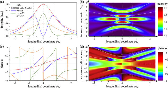
Figure 11. (b) Intensity distribution of the simple slit mode in the x−z-plane around the focus and (a) intensity course on the optical axis (x = y = 0) and at distances x = w(z)/21/2 and x = w(z)31/2 from the optical axis, where the simple slit mode exhibits maxima in the focal plane. These curves are indicated with white dotted lines in panel (b). The on-axis intensity of the fundamental mode GH0,0 with the same q-parameter and with the same power is shown for comparison. The intensities are normalized to the maximal intensity of the fundamental mode. The focal plane and the plane of maximal intensity of the slit mode at a distance of ±zR/21/2 are indicated with white dashed lines. (d) Distribution of the phase in excess to a plane wave for the simple slit mode in the x−z-plane around the focus and (c) phase evolution along the same curves as in panel (a). A shift of the position of zero on-axis intensity with respect to the focal plane for the slit mode is neglected (the Gouy phase for propagation from the focal plane to the slit mirror is not exactly π/2, because it is not infinitely far away). Also the mode is assumed to be non-elliptic and non-astigmatic.
Download figure:
Standard image High-resolution imageThe intensity lobe before or behind the focus or the two lobes around the focus can be readily accessed by a gas nozzle from the y-direction, which is perpendicular to the drawing plane in figure 11(b), because the intensity profile is Gaussian in this direction. Also, multiple gas jets could be employed, thereby achieving quasi-phase-matching between e.g. the on-axis lobes before and behind the focus [33].
The intensity and phase distribution around the focus can be changed by the contribution of higher-order slit modes, as well as by tailoring the ellipticity and astigmatism of the resonator mode. It remains to be investigated theoretically and experimentally, how the circulating field can be tailored by the shape and position of apertures, the impinging field distribution and the position in the stability range. The possibility of tailoring the circulating field distribution in an enhancement resonator for HHG might open new prospects for increasing the conversion efficiency by improving phase-matching.
8.2. Non-collinear setup
A (quasi-)imaging enhancement resonator is closely related to a non-collinear setup, with two Gaussian beams intersecting in the focal plane under a small angle (figure 12(a)). High harmonics generated in the focus can be coupled out through a gap between the focusing mirrors. To this end, the two beams can be enhanced using two appropriately arranged stable enhancement resonators [34]. Also, a single stable enhancement resonator with length equal to two times the laser resonator length and two pulses circulating can be applied [22]. The resonator geometry has to be arranged for the pulses to overlap in time, and the two halves of the resonator have to be stabilized such that the two pulses will maintain constructive interference on the optical axis. This non-collinear setup can be simplified by using a degenerate resonator and a beam with an offset to the optical axis that oscillates transversally while it retraces its path after N = 2π K/ψE,x round trips with the Gouy parameter ψE,x and an integer K [35]. The resonator degeneracy and synchronization of the pulses can be adjusted by a single parameter. In case of an imaging enhancement resonator the overlap and synchronization of two pulses circulating in a resonator with length equal to the laser resonator length is then inherently linked to the condition of the degeneracy. The high harmonics would be coupled out through a slit in the mirror behind the focus. In order to realize the situation in figure 12(a) the resonator has to be imaging (magnification –1) with the beam retracing its path every other round trip.
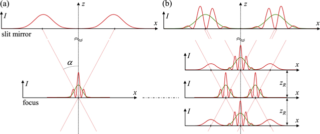
Figure 12. Intensity profiles I (x, y = 0) of intersecting Gaussian beams. (a) Two beams intersecting in the focal plane. The beams are sufficiently separated in the far field on the focusing mirror to allow for a slit at x = 0 (or a gap between two independent mirrors). (b) Oscillating beam in a stable enhancement resonator, retracing its path after four round trips. The red lines show the intensity profiles if two (a) or four (b) pulses are circulating; the green lines show the profiles if only one pulse is circulating. In the drawings the non-collinear angle α is two times the far field divergence angle.
Download figure:
Standard image High-resolution image
The simplest case of a stable resonator is shown in figure 12(b), with the beam retracing its path after N = 4 round trips, like for a bow-tie resonator in the middle of the stability range. For a non-collinear setup, a small angle between the two beams is preferable, because it decreases the number of interference fringes in the focus, which determines the divergence of the high harmonics. The simple mode combinations shown in figures 2(g) and figure 2(a) correspond to the situations in figures 12(a) and (b) with the smallest possible non-collinear angle. In this sense, an imaging or quasi-imaging enhancement resonator can be regarded as a perfect non-collinear setup with smallest non-collinear angle and inherently synchronized non-collinear beams.
8.3. Comparison to other concepts for geometrical on-axis access
The conceptually simplest concept for geometrical output coupling is a circulating fundamental mode and a small circular hole in the resonator mirror following the focus. Recently, geometrical output coupling of high harmonics based on this concept was demonstrated for the first time [23]. The hole has to be very small compared to the fundamental mode beam diameter, in order to allow for a high enhancement (figure 3), which limits the output coupling efficiency. However, this limitation is not so strong for harmonics of high order, i.e. short wavelengths, because the far field divergence angle of the generated harmonics decreases with decreasing wavelength. The output coupling efficiency is estimated to greater than 0.5 for the highest harmonic generated (91st harmonic, corresponding to 11.45 nm) in [23], with the hole allowing for a power enhancement of 250. The output coupling efficiency decreases to less than 0.1 for wavelengths around 70 nm. Therefore, HHG with a slit or hole mode in a quasi-imaging resonator, which allows for a larger opening, is especially beneficial for harmonics of moderate order (e.g. 17th). Furthermore, the small intensity at the edges of the slit or hole in a mirror is expected to be advantageous, because a high intensity can lead to damage. For both methods the manufacturing of mirrors with small-size holes or slits is essential, which was recently demonstrated with inverse laser drilling by Esser et al [29]. In comparing these methods it has to be considered that the exploitation of a mode degeneracy for quasi-imaging and therefore the predefinition of a position in the stability range of the enhancement resonator represents a restraint for the resonator design (see section 4). It is e.g. not possible to move towards the border of the stability range, in order to achieve larger mode cross sections for the scaling to higher circulating power, as is discussed and demonstrated in [28, 36].
Another promising method for geometrical output coupling of high harmonics is a Bessel−Gauss beam enhancement resonator with an on-axis intensity maximum in the focus and an annular intensity distribution in the far field, which allows for a large opening in a resonator mirror [31, 37, 38]. The suitability of this field distribution for efficient HHG still has to be investigated. A constraint might be the large and radially symmetric extent of this field distribution around the focus, which impedes the accessibility for a gas nozzle. Furthermore, Bessel−Gauss beam resonators seem to be very sensitive to surface imperfections of the resonator mirrors [38].
9. Conclusion
We described a new concept providing a geometrical on-axis access to a high-finesse enhancement resonator, which we call quasi-imaging. A quasi-imaging resonator is a stable resonator with a degeneracy of transverse modes and an obstacle in the beam path providing the access. Eigen-modes of the quasi-imaging resonator can be constructed as a combination of simultaneously resonant modes, which avoid the obstacle and exhibit small loss. Geometrical output coupling of intracavity-generated high harmonics has several advantages over alternative output coupling methods, including power scalability, large bandwidth and collinear harmonics, which are necessary prerequisites for the generation of single attosecond pulses. A simple and advantageous setup is a bow-tie enhancement resonator in the middle of the stability range with quasi-imaging in one transverse direction and a circulating slit mode. This is easily adjusted and allows for a large enhancement [7]. The slit mode offers a good accessibility for a gas nozzle. We demonstrated the suitability of the field distribution for HHG in [8]. Tailoring of the circulating transverse mode in a quasi-imaging enhancement resonator offers prospects for an increase of the harmonic yield in the future.
Acknowledgment
This work was supported within the cooperation projects KORONA and MEGAS between the Max-Planck-Institut für Quantenoptik (MPQ) and the Fraunhofer-Institut für Lasertechnik (ILT).