
Abstract
Irradiation of moving targets using a scanned ion beam can cause clinically intolerable under- and overdosages within the target volume due to the interplay effect. Several motion mitigation techniques such as gating, beam tracking and rescanning are currently investigated to overcome this restriction. To enable detailed experimental studies of potential mitigation techniques a complex thorax phantom was developed. The phantom consists of an artificial thorax with ribs to introduce density changes. The contraction of the thorax can be controlled by a stepping motor. A robotic driven detector head positioned inside the thorax mimics e.g. a lung tumour. The detector head comprises 20 ionization chambers and 5 radiographic films for target dose measurements. The phantom's breathing as well as the 6D tumour motion (3D translation, 3D rotation) can be programmed independently and adjusted online. This flexibility allows studying the dosimetric effects of correlation mismatches between internal and external motions, irregular breathing, or baseline drifts to name a few. Commercial motion detection systems, e.g. VisionRT or Anzai belt, can be mounted as they would be mounted in a patient case. They are used to control the 4D treatment delivery and to generate data for 4D dose calculation. To evaluate the phantom's properties, measurements addressing reproducibility, stability, temporal behaviour and performance of dedicated breathing manoeuvres were performed. In addition, initial dosimetric tests for treatment with a scanned carbon beam are reported.
Export citation and abstract BibTeX RIS
General scientific summary Irradiation of moving targets using a scanned ion beam can cause under- and overdosages within the target volume due to the interplay effect. Several motion mitigation techniques are currently investigated to overcome this restriction. To enable detailed experimental studies of mitigation techniques, a complex thorax phantom was developed. The phantom consists of an artificial thorax whose contraction can be controlled by a stepping motor. A robotic driven detector head inside the thorax mimics e.g. a lung tumour. The phantom's breathing as well as the 6D tumour motion can be programmed independently and adjusted online. Commercial motion detection systems can be mounted as in a patient case. This flexibility allows e.g. studying the dosimetric effects of correlation mismatches between internal and external motions. To evaluate the phantom's properties performance measurements were conducted including dosimetric irradiation tests using a scanned carbon.
1. Introduction
Treatment of moving tumours using radiotherapy is more challenging than treating stationary targets. Using intensity-modulated radiotherapy (IMRT) or scanned particle therapy (IMPT) (Haberer et al 1993, Pedroni et al 1995), irradiation of moving targets can cause clinically unacceptable under- and overdosage due to the interplay effect (Bortfeld et al 2002, Chui et al 2003, Phillips et al 1992). Thus, while in conventional photon therapy and in particle therapy using beam scattering (Chu et al 1993) an increase of the PTV can lead to an acceptable target dose, in IMRT and IMPT more complex mitigation techniques were proposed. The three suggested techniques for IMPT are rescanning (Phillips et al 1992), gating (Minohara et al 2000) and beam tracking (Groezinger et al 2004). For the last two techniques and for some rescanning techniques (Furukawa et al 2007, 2010, Seco et al 2009), a motion monitoring system is mandatory. Since an additional patient dose can be high when using fluoroscopy for direct tumour position determination (Shirato et al 2004), it was also proposed to apply surrogate signals to identify the motion state (Evans 2008).
If a surrogate signal is used, one has to ensure that the correlation between the internal tumour motion and external motion signal is well known. Several groups compared surrogate signals to the real tumour motion based on patient data (Beddar et al 2007, Gierga et al 2005, Hoisak et al 2004, 2006, Ionascu et al 2007, Kanoulas et al 2007, Liu et al 2004, Otani et al 2010, Tsunashima et al 2004). In some cases a good correlation was found, but some groups reported dependences on patient, applied surrogate and reference points/marker positions. Phase shifts (time shifts) were observed as well as organ drifts due to muscle relaxation (von Siebenthal et al 2007a, 2007b, Sonke et al 2008). The study of patient data is necessary for judging clinical relevance, but to estimate dosimetric effects of wrong correlation systematically proper phantoms are needed. Such a phantom can be very helpful for treatment plan validation and robustness analysis as well as for testing within the technical development of new mitigation techniques or correlation models.
For use in ion beam RT, we defined criteria for the minimum functionality of the phantom (non-weighted order).
- (i)Breathing, deformable thorax comprising ribs (inhomogeneous material in front of the target for e.g. beam tracking experiments).
- (ii)Capability of performing 6D internal target motion (without deformation) independent from thorax motion.
- (iii)Online adjustable correlation between the internal target motion and external thorax motion.
- (iv)Capability of starting and stopping the target and thorax motion in any motion phase.
- (v)Detector head representing the tumour equipped with multiple ionization chambers and films.
- (vi)External motion applicable to surface imaging (e.g. the VisionRT system (Vision RT Ltd, London, UK)) and other systems like the Anzai belt (Anzai Medical Co., Ltd, Tokyo, Japan) or RPM (Varian Real-time Position Management™—Varian Medical Systems Inc., Palo Alto, CA).
- (vii)4DCT compliance, e.g. no metal.
- (viii)Extendable I/O signal interfaces, e.g. triggered motion start or beam gate output.
- (ix)High flexibility, e.g. possibility to exchange the detector head by a different one.
There are a few commercial motion phantoms available e.g. by QRM (Sim4D+Thorax-Phantom—QRM GmbH, Moehrendorf, Germany), MODUS-QA (qasar respiratory motion phantom—Modus Medical Devices Inc., London, CA), StandardImaging (Respiratory Gating platform—Standard Imaging Inc., Middleton, WI, USA), CIRS (Dynamic Thorax Phantom—CIRS Inc., Norfolk, VA, USA) and RSD (Dynamic Anatomical Respiring Humanoid Phantom—Radiological Support Devices Inc., Long Beach, CA, USA). Only the last two are capable of performing independent internal and external motion, but also these are not matching the requirements mentioned above (e.g. multiple ionization chambers).
This lack of commercial availability causes also other groups to build their own phantoms. For example, Alasti et al (2006), Dietrich et al (2005), D'Souza et al (2005), Ford et al (2003), Gemmel et al (2010), Jiang et al (2003), Keall et al (2001) and Rietzel et al (2005) used a motion stage or a moving arm to move radiopaque objects or detectors. Others went a more complex way by, in addition, introducing anthropomorphic structures or more complex motion (Followill et al 2007, Kashani et al 2007, Li et al 2005, Nioutsikou et al 2006, Serban et al 2008, Vinogradskiy et al 2009). Biederer and Heller (2003) even built up an artificial thorax to perform breathing motion studies with real animal lungs.
All of these phantoms match one or more of the criteria mentioned above, but there is no phantom which would cover our needs completely. Thus in this paper, we present our solution of a complex motion thorax phantom we will use for 4D treatment plan studies, robustness investigations and for testing within technical development of new mitigation techniques.
2. Materials and methods
2.1. The thorax
The basis of the artificial thorax is a commercial artificial skeleton (Skelett Bruce—Teng Long Trading GmbH & Co KG, St. Pölten, Austria) which consists of polyvinyl carbonate (PVC). All but the thorax was removed and all metal components used by the manufacturer to connect the plastic bones (screws, wires, rods) were exchanged with plastic. After that the thorax was surrounded by rubber to generate a skin-surface and inter-rib material. This led to a thorax wall thickness of about 1 cm. The artificial thorax is shown in figure 1(a). Rather than using anthropomorphic materials that are equivalent to that of bone/tissue, we chose to use a dedicated lookup table to convert the Hounsfield units (HU) of the CT scan into water-equivalent path lengths (WEPL) for use with particle irradiation (Jaekel et al 2001) as is also carried out for patient treatment planning.
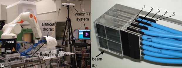
Figure 1. (a) Photograph of the setup at GSI showing also the VisionRT system. The detector head is shown in irradiation position within the artificial thorax. For further illustration, a video attachment can be found online (available from stacks.iop.org/PMB/57/2235/mmedia) showing correlated motion of the target and thorax. (b) Picture of the fully equipped detector head. Four rows of pinpoint ionization chambers with five chambers per row are used for 3D dosimetry within the target volume. In between the rows, in front of the first and behind the last row light-proof film cases are placed (black plates) covering radiographic films for homogeneity measurements.
Download figure:
Standard image2.2. The tumour (detector head)
The tumour is represented by a cube consisting of polymethyl methacrylate (PMMA) which provides slots for 20 pinpoint ionization chambers (PTW PinPoint® model 30 009/30 015—PTW, Freiburg, Germany) and five light proof film cases covering radiographic films (detector head).
We decided to use radiographic films instead of Gafchromic films, because the only available Gafchromic films (EBT2 films) turned out not to be useful for homogeneity measurements using ions (Hartmann et al 2010). Therefore, light proof cases had to be constructed to cover small radiographic films (Kodak X-Omat V—Kodak GmbH, Stuttgart, Germany). These cases were made up of black PVC plates of 1 mm thickness. The plates were cut to a size of 5 × 7 cm2. Then each of these was milled to generate space for a film of 4.6 × 6.8 cm2 size. After that a second 5 × 7 cm2 sized plate of the same material was glued on top of the milled one.
Figure 1(b) shows the detector arrangement within the detector head. In beam eye view (BEV) projection, the pinpoints have a lateral distance of 1 cm from each other. The rows are at a distance of 12 mm (compare also figure 3) from each other. The film cases can easily be replaced by non-irradiated ones. Re-equipping of a set of five film cases is doable in less than 10 min in a dark room. The films were developed using a standard development machine (Kodak X-Omat M35—Kodak GmbH, Stuttgart, Germany; Agfa Curix 60—Agfa-Gevaert N.V., Mortsel, Belgium).
2.3. Motion control
2.3.1. Thorax motion
A nylon cord which is attached to the sternum is periodically pulled and released by a stepping motor (AS1050—200 full steps per revolution, micro step factor 64—Beckhoff Automation GmbH, Frankfurt, Germany) via a lever arm (PMMA). This pulling results in contraction and deformation of the thorax and, therefore, introduces thorax motion. The stepping motor is placed at the edge of the base plate (PMMA) to avoid having metal in the scanning field of the CT (figure 1(a)).
The motor motion intrinsically is measured by an incremental encoder (1024 increments per revolution) and, in addition, by a laser distance sensor (Model OD100-35P840—SICK AG, Waldkirch, Germany) which measures the distance to the moving lever arm.
2.3.2. Target motion
Motion of the detector head should be as flexible as possible to be able to simulate complex tumour motion. Therefore, the detector head was mounted on to a robotic arm (KUKA KR 5 sixx R850—KUKA Roboter GmbH, Augsburg, Germany) which was programmed to synchronize motion to the thorax motion. The motion trajectory is defined by a list of N points Pi(x, y, z, rx, ry, rz), i = 1, ..., N which is executed periodically. Thus the target can perform arbitrary motion patterns independently from the thorax motion.
The target motion is intrinsically measured by the encoders of each robot axis and transformed to a 6D position information in Cartesian coordinates each of 2 ms. In addition, the SI (superior–inferior) motion is measured using a second laser distance sensor.
2.3.3. Motion correlation
The thorax and robot motions are both controlled by the robot control system. The stepping motor is connected to a stepper control device which is integrated in a Beckhoff I/O system (extendable, programmable bus terminal system; see section 2.4). The stepper controller executes commands given by the robot controller in real time.
Due to technical constraints, controlling fixed or defined varying correlations between the thorax and target motion is divided into two phases: the pre- and the main-run. During the pre-run, target and stepper velocities are calculated and synchronized based on the given Pi and the planned motion period T. In the main-run, motion is periodically executed.
Constant phase shifts as well as phase drifts, i.e. an increase of a phase shift during motion, and baseline drifts, i.e. drifts of the target motion in interior direction (x) during motion, can be performed. In addition, the robot control system can react to connected input signals which can be used to manipulate motion behaviour online (see also section 2.4.3).
2.4. I/O interfaces
2.4.1. Motion logging
The analogue signals of the two laser distance sensors measuring the stepping motor motion and one projection of the target motion are directly provided and can be fed into an analogue-to-digital converter to be logged to a file. In our experiments we use a Beckhoff EtherCAT™ system (Beckhoff Automation GmbH, Frankfurt, Germany) in combination with a Windows PC. In addition, after each 2 ms a logging data set Lj(t) = (tj, Pj(x,, y, z, rx, ry, rz)) is written to an user datagram protocol (UDP) interface, providing the current system clock counter tj and the current position Pj. Using dedicated software on a Windows PC these position logging data can be written to a file.
2.4.2. Remote control
Since entering an irradiation cave always takes time, the robot software was implemented in a way that it can be controlled remotely. Remote access is realized using normal TCP/IP network interfaces and controlled PCs outside the cave. Only the change of film cases causes the need of entering the irradiation cave.
2.4.3. Multiple IO
The I/O device described in 2.3.3 also provides four digital inputs and outputs for 24 V TTL signals and 12 digital inputs and outputs for 5 V TTL signals. These interfaces can be customized and are currently used to trigger motion start or feed status outputs into the data acquisition during measurement. In addition, it can in principle be used to gate the beam.
2.5. Validation experiments
2.5.1. Target motion (robot)
One hundred forty six robot log files have been analysed to determine the precision of the robotic motion. In all these cases the robot was moved following a 3D sinusoidal trajectory defined as follows:
where the peak-to-peak amplitude AP was varied from 2 to 20 mm and the period T was set to 3 s.
Based on the information in all motion log files the 3D motion was compared to the nominal motion amplitudes and shapes.
2.5.2. Thorax motion
Reproducibility of the thorax motion was evaluated with the VisionRT system. The relaxation position of the deformable thorax seemed not to be the motion maximum during motion. To investigate this effect and, in addition, the potential extension of the cord, several long-term tests were performed. The thorax motion was monitored for durations between 30 and 60 min. Reproducibility was tested by changing behaviour between different motion detection sequences. Motion was just stopped and restarted between two runs or the lever arm was shortly disconnected from the cord and reconnected prior to motion restart. In addition, the time between motion stop and restart was varied. During all these measurements the tracking point of the VisionRT system was set to the sternum.
2.5.3. Dosimetry
To allow treatment planning we performed 18 3DCT scans (Somatom Sensation Open—Siemens AG Healthcare, Erlangen, Germany; resolution: 1 × 1 × 1 mm3), one for each motion state every 20º distributed over one thorax motion cycle. (The topogram and one axial slice are shown in figure 2.) The detector head CT was incorporated into the 4DCT phases according to the planned motion using a dedicated CT merging software. Thus, we generated a 4DCT free-of-motion artefact and a higher number of motion states than normally used for standard 4DCT reconstruction. To ensure having the right HU values, we measured the WEPL of material samples using the PTW Peakfinder™ (PTW, Freiburg, Germany) and a carbon beam at Heidelberg Ion-Beam Therapy Center (HIT, Heidelberg, Germany). Then we replaced the HU values with the ones corresponding to the measured WEPL values (Jaekel et al 2001).
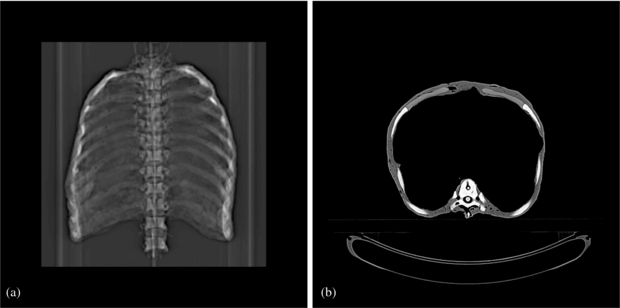
Figure 2. CT scan of the thorax. (a) Topogram. (b) Representative axial slice.
Download figure:
Standard imageFor the dosimetric test based on the CT a plan was optimized to deliver a homogeneous dose of 1 Gy to a cubic target volume of the size of the detector head (figure 3) using a scanned carbon beam. This optimization was done for two plans one for irradiation of the pure detector head in air and the other for irradiation of the detector head in the thorax. A bolus of 4 cm PMMA was used to increase the energies for the optimization. Six types of irradiations were performed to investigate effects of the single components:
- (i)a static detector head in air,
- (ii)a moving detector head in air,
- (iii)a static detector head in the static thorax,
- (iv)a static detector head in the moving thorax,
- (v)a moving detector head in the static thorax and
- (vi)a moving detector head in the moving thorax.

Figure 3. Cuts through the calculated dose distribution of stationary irradiation of the target. The crosses indicate the measuring positions of the 20 ionization chambers (projected onto the particular cutting plane). (a) BEV, (b) view from the right-hand side, and (c) top view. In (b) and (c) the beam comes from the left.
Download figure:
Standard imageThe detector head was moved as described in equation (1) using a peak-to-peak amplitude AP of 10 mm and a period T of 3 s.
Furthermore, gated irradiation was tested using the Anzai system to show baseline drift and phase shift functionality. The effect of a baseline drift was tested by comparing the gated irradiation with AP = 10 mm peak-to-peak motion and a gating window of 50% combined with drifts of 0, 0.2 and 0.4 mm per period. In the case of phase shift, shifts between the target and thorax motions of 0º and 90º were introduced. Using these shifts a target motion of AP = 20 mm peak to peak was irradiated using gating based on the external motion signal with a gating window of 25%. The VisionRT system was used to monitor the thorax motion in parallel using the sternum as a tracking point location. Whereas the target point in the non-gated irradiations was set to the centre of the 3D motion, in the gating cases it was set to the gating window centre (minimum of target motion—BEV leftmost position).
Measured doses were compared to the doses calculated using our in-house treatment planning system TRiP98 (Kraemer et al 2000). To compare also the interplay patterns measured in the moving cases, 4D dose distributions were reconstructed based on the beam delivery record, 4DCT and motion trace (Bert and Rietzel 2007, Richter et al 2010). Therefore, besides the automatically saved machine beam record the laser signals and the beam status signal were recorded using a Beckhoff EtherCAT system with 1 ms acquisition rate to have a temporal correlation between the beam and motion. Additional signals (e.g. a Geiger counter output) were also logged in the same system to gather more information than essential to gain redundancy. Comparison was done according to treatment planning verification at GSI (Karger et al 1999).
Since the dose gradients can be very steep, agreement between measured doses and doses extracted from the calculated dose distribution is very sensitive on positioning errors. Therefore, the extraction positions were varied in all six degrees of freedom around the nominal extraction position to estimate if a potential positioning error occurred.
3. Results
3.1. Motion precision
3.1.1. Target motion (robot)
Figure 4 shows a comparison between the logged and planned trajectories for two randomly chosen cases taken from the 146 robot log files which have been analysed. In some small amplitude cases near the turning point small dips were observed (figure 4(b)). In all cases the found amplitudes are systematically a little smaller than the planned ones which is due to the way the robot calculates its motion path in turning points. This deviation is less than 2% in all measured cases. To check the shape of the logged trajectories each period of each log data was compared to sinusoidal curves with amplitudes adjusted to the measured ones. It was found that in all cases the logged trajectories differ from a perfect sine by (0±0.09) mm. The periods derived from the maxima positions in all log files were found to be (3000±3) ms.
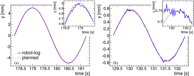
Figure 4. Representative example of robot trajectories. Plots of two randomly chosen cases at random time for a small and a large amplitude. Shown is the planned (red line) and the logged (blue line) trajectories for one period in y. In the right top area of each plot a zoomed view to the maximum area is shown. (a) AP = 20 mm peak-to-peak motion in x. (b) AP = 3 mm peak-to-peak motion in x.
Download figure:
Standard image3.1.2. Thorax motion
VisionRT data showed in some cases a transient effect in the thorax motion depending on the time the thorax was not moved before starting a new measurement. Figure 5 shows an example a comparison of VisionRT measurements of the thorax motion after a very long (12 h) and a very short (10 s) pause between two thorax motions. For realistic pauses of a few minutes (in our dosimetry tests), we observed a signal drift of up to 20% (relative to tracking point motion amplitudes of about 2 mm). After up to 60 s the thorax motion stayed stable.

Figure 5. Long-term VisionRT measurements of the thorax motion. The detected maxima (black line) and minima (red line) of the measured trajectories are plotted over time. (a) Motion has been started 12 h after the last one was stopped. (b) Motion has been started right after the last one was stopped. The spikes at the beginning and the end of the measured trajectories are due to slight wobbling of the camera tripod which was caused by entering and leaving the room, respectively.
Download figure:
Standard image3.2. Irradiation experiments
3.2.1. Film results
Figure 6 shows an example two sets of irradiated films which were put into the detector head during the dosimetric test experiments. The static case shows a very homogeneous blackening, while an interplay pattern can be seen in the moving case. Because the films are in part covered by the pinpoint ionization chambers, one can see shadows of the chambers on the more distal positioned films.

Figure 6. Two film sets irradiated using a scanned carbon beam within the detector head. Upper row: stationary case. Lower row: moving case. The film number specifies the position in the detector head (compare figure 1(b)). The yellow contours indicate the pinpoint positions of the row in front of a certain film.
Download figure:
Standard image3.2.2. Dose results
As an example figure 7 shows a recalculated interplay pattern. It confirms the assumption mentioned above. Sharp gradients at least in the left–right direction (x) can be seen causing a high sensitivity of dose agreement between measurement and calculation on setup errors. Shifting and rotating of the extraction position within the calculated dose distribution resulted in a clear minimum in dose deviation only for a shift in x and for two angles (rotation around y- and z-axes) (Δx = 1.1 mm, Δry = 0.2°, Δrz = −0.2°). In table 1, the measured doses and the deviations from the planned dose are given. Furthermore, it lists the results for comparison between measured and calculated doses relative to the measured doses.

Figure 7. Exemplary plot of cuts through the recalculated dose distribution of an interplay (case 2 in table 1). The crosses indicate the measuring positions of the 20 ionization chambers (projected onto the particular cutting plane). (a) BEV, (b) view from the right-hand side, and (c) top view. In (b) and (c) the beam comes from the left. The interplay pattern shows sharp gradients in the x direction (left–right).
Download figure:
Standard imageTable 1. Results of pinpoint dose measurements. Given are the measured doses DM as well as the relative deviations of the measured doses from the planned dose of 1 Gy (ΔDM − P) and the relative deviations from the reconstructed dose distributions (ΔDM − C), respectively. Comparison to the calculations is reported for the nominal and the corrected (Δx = 1.1 mm, Δry = 0.2°, Δrz = −0.2°) extraction position.
| ΔDM − C | |||||||
|---|---|---|---|---|---|---|---|
| No. | Setup | Target | Thorax | DM (Gy) | ΔDM − P (%) | Nominal (%) | Corrected (%) |
| 1 | Detector head only | Static | – | 0.99 ± 0.01 | −0.9 ± 0.8 | 1.0 ± 1.0 | 0.9 ± 0.9 |
| 2 | Detector head only | Moved | – | 0.93 ± 0.05 | −7.5 ± 5.4 | −4.4 ± 9.9 | 1.6 ± 3.3 |
| 3 | Phantom | Static | Static | 0.99 ± 0.01 | −1.2 ± 0.9 | 1.3 ± 1.0 | 1.2 ± 1.0 |
| 4 | Phantom | Static | Moved | 0.99 ± 0.01 | −1.3 ± 1.0 | 0.6 ± 1.4 | 1.0 ± 1.0 |
| 5 | Phantom | Moved | Static | 0.99 ± 0.10 | −0.7 ± 10.0 | 1.7 ± 7.9 | 1.2 ± 5.8 |
| 6 | Phantom | Moved | Moved | 0.90 ± 0.18 | −10.5 ± 17.7 | 0.8 ± 7.0 | 1.2 ± 5.1 |
3.2.3. Baseline drift
An overview of all the measured signals using the Beckhoff EtherCAT system can be seen in figure 8. The target motion drifts to lower values (corresponding to the BEV right direction), while the thorax motion stays constant. It can also be seen that within a certain 'beam available gate' the beam is delivered in pulses (slope of Geiger counter signal) within the gating windows only.

Figure 8. Measured signals using the Beckhoff EtherCAT system for a baseline drift measurement.
Download figure:
Standard imageFigure 9 shows exemplarily the results of the doses for the baseline drift measurements. It can be seen that in the case of a large baseline drift the dose in the chambers placed at the rightmost leaves at some point the target volume and get less dose.

Figure 9. Measured doses of the 20 pinpoint ionization chambers in BEV projection. Values are normalized to the doses measured in the stationary case. In the top centre of each plot the mean deviation and its standard deviation are listed. (a) Interplay without drift. (b) Baseline drift with 0.2 mm per period. (c) Baseline drift with 0.4 mm per period. The drift direction was BEV to the right (x).
Download figure:
Standard image3.2.4. Phase shift
Analysis of the measurements done using the Beckhoff EtherCAT system (see also figure 8) showed that the phantom was able to perform shifts between the thorax and target motion. For the two applied phase shifts, dose deviations of (2.4±4.0)% (0º phase shift) and (2.7±3.3)% (90º phase shift) relative to the stationary measurements were found.
4. Discussion
4.1. Phantom construction
The presented phantom has a thoracic structure in terms of bony anatomy and water equivalent inter-rib material and thoracic shape as done by some groups found in literature. While in our phantom the lungs are filled with air, Nioutsikou et al (2006) and Vinogradskiy et al (2009) introduced sponges to represent the lung equivalent material. Serban et al (2008), in addition, modelled substructure-like bifurcations into the lung sponge. Biederer and Heller (2003) even used a real lung. Usage of real organs is not very handy for systematic studies which may take longer time since durability is limited and exchange of the organ results in the need of a new 4DCT. Realistic substructures and tumour composition also makes usage for 3D dosimetry and complex tumour motion difficult. Therefore, we reduced complexity for the inner thorax structure to a minimum to focus on the correlation and complex target motion. The introduction of sponge as a lung tissue may be done in a second improved version of the phantom. This improved version should also comprise anthropomorphic materials rather than using PVC and rubber. Despite the dosimetric agreement of measurements and calculations (see table 1), the currently used artificial materials might show increased scattering and nuclear fragmentation than a patient, especially for an application in proton beam therapy.
In contrast, bony anatomy is important for our needs to have inhomogeneities in the entrance channel which only exists in a few phantoms in the literature. Kashani et al (2007) combined the realistic bony structure and internal composition, but the thorax cannot breath which is important to enable the usage of external motion sensors like the Anzai belt as they would be used in the patient case. There is one commercial phantom capable of doing thorax deformation according to breathing: the Dynamic Anatomical Respiring Humanoid Phantom by RSD (Radiological Support Devices Inc., Long Beach, CA, US) uses compressed air for breathing and target motion, but it is only capable of performing 1D motion. For the specific experiments reported in section 3.2.2 the ribs did not show a major impact on the dose distribution. Apart from averaging effects resulting from multiple beam positions that contribute to the dose of an ionization chamber, also the motion pattern of the ribs contributed to this effect. For the lateral beam direction of the experiments, the rib motion was mainly in the beam direction and thus slightly different from the rib motion in a patient which has a cranio-caudal component. Upgrades of the thorax phantom should consider these limitations.
Most phantoms used are only capable of performing 1D or 2D target motion. Serban et al (2008) and Nioutsikou et al (2006) introduced a 3D motion to their target (tumour) by pushing an artificial diaphragm. This motion is reproducible, but not predictable/adjustable. Nioutsikou et al (2006) constructed a phantom capable of performing 3D motion following regular or even irregular trajectories, but target rotations cannot be incorporated to the motion trajectories and the phantom is not able to perform the external thorax motion which both can be done with the presented phantom. There are two commercially available systems providing 3D internal and 1D external motion: the Qasar Respiratory Motion Phantom (Modus Medical Devices Inc., London, CA) and the Dynamic Thorax Phantom (CIRS Inc., Norfolk, VA, USA). Only the last one can perform the motion independently, but the use of, e.g. , an Anzai belt is not possible since external motion is realized by an up-and-down moving platform (only the Anzai laser could be used or e.g. the Varian RPM) and, thus, is not patient like. In addition, the correlation cannot be adjusted during measurement, and 3D dosimetry using multiple ionization chambers is not possible with these two systems. In contrast, our phantom now combines target motion in six degrees of freedom with the independent thorax motion. While the target can follow any trajectory and, in principle, even real measured tumour trajectories, the thorax motion pattern could not be changed so far. To introduce more realistic signals for external motion sensors, it is planned to exchange the controller of the Beckhoff I/O device by a more intelligent one which then may take over parts of the stepper motion control triggered by the robot control system.
There are several reported phantoms using films and ionization chambers for dosimetry. Nioutsikou et al (2006) even used several films to measure the 3D dose distribution within the target, but without incorporating ionization chambers. If ionization chambers are used, only one chamber is placed in the moving target which is not enough to measure the interplay patterns of scanned ion beams. Multiple ionization chambers have been used only in static dose verification so far (Karger et al 1999, Lomax et al 2004). In our phantom, a film stack and an ionization chamber stack were combined to measure homogeneity with high spatial resolution (films), but also the 3D dose distribution.
Thus, the phantom presented here differs from all commercially available phantoms and those presented in the literature mainly in two characteristics. The correlation of a deformable breathing thorax with a target movable in six degrees of freedom (any motion trajectory e.g. a real tumour motion) and usage of a combination of multiple ionization chambers and multiple films for target dose measurements. In addition, it is capable of triggering external systems (like gating the beam) or being triggered to start moving in a certain motion state.
In comparison to phantoms used in previous dosimetric studies (Lüchtenborg et al 2011, Bert et al 2010, Gemmel et al 2010), the main benefit of the robotic phantom reported here is the advanced motion characteristics. With a 6D tumour motion that is independent of the thorax motion, the clinical situation is mimicked more closely including the assessment of various motion monitoring systems as they can be applied in patient treatments. Due to the independently adjustable motion of each tumor and thorax, an intentionally changed correlation between internal motion and external motion surrogate can be introduced as a source of potential error. Its influence on the dose distribution is of importance especially for gating or beam tracking. The features of the phantom can be used for robustness analyses (i.e. dosimetric sensitivity to changes in motion or correlation parameters) for different treatment delivery options already in the development phase. Patient-specific treatment plan validation can be based, e.g., on the motion trajectory measured in the 4DCT acquisition. Apart from testing the technical ability to deliver the optimized treatment plan (involving e.g. time requirements in case of gating), the dosimetry can be assessed by comparing the measured dose levels of the ionization chambers with reconstructed ones of the 4D dose calculation with the actually delivered parameter set. The measured parameters can then be used to calculate the 4D dose distribution based on the patient's 4DCT to assess, e.g., interference effects in the CTV. Furthermore, ideas came up to use the phantom for 4D imaging validation purposes. Usage with magnetic resonance imaging is not possible due to the metal components, but validation experiments for 4D positron emission tomography (PET) which can be used for the verification of treatment delivery in ion therapy (Parodi et al 2009) are performable using the phantom. The target holder can easily be equipped with a target appropriate for PET. This flexibility in respect of a target detector implies that the phantom can also be used for biological experiments such as cell survival measurements as e.g. performed by Gemmel et al (2010).
4.2. Validation experiments
Target motion turned out to be very precise in both timing and positioning. Reproducibility is better than reported by Serban et al (2008) and Kashani et al (2007) which is not surprising if using a robotic system.
Thorax motion showed baseline drifts directly after motion start due to transient effects. Since this effect is dependent on the time between two motion sequences, it can easily be overcome by ensuring that the motion pauses in between two measurements are short and motion is started prior to the measurement according to the pause. For usual pauses of a few minutes between two irradiation experiments, we found that it is sufficient to start motion 60 s prior to the irradiation. However, for some experiments it may be necessary to start motion in a certain motion phase synchronously with the irradiation. In this case, the baseline drift of the thorax motion can be minimized by keeping pauses between the irradiations short.
Comparison of measured and calculated doses shows very good agreement at least for position-corrected dose extraction. Setup errors based on positioning lasers of 1.1 mm lateral and 0.2ºin two angles are reasonable. The found dosimetric deviations are acceptable, since Karger et al (2010) reported expected uncertainties of up to 3% for static dose measurements which can be even higher if inhomogeneous material comes into play. Since in the static cases planned dose could be measured and, furthermore, in all cases the measurements are in good agreement with calculations, the phantom turns out to be usable for dosimetric studies.
Baseline drift and phase shift functionality could be successfully tested during the validation experiments.
5. Conclusion
We presented a highly flexible motion phantom which is able to perform independent internal and external motion. An exchangeable detector head is moved in 6D within a moving thorax with ribs. The detector head comprises five radiographic films and 20 pinpoint ionization chambers for 3D target dose measurements. The phantom is CT and ion beam compatible and can perform baseline drift, phase shifts and phase drifts of the target motion. The phantom was successfully tested with and without the beam. Some quantitative experiments have already been done using this device and further experiments are in preparation.
Acknowledgments
We would like to acknowledge all colleagues of the Heidelberg Ion-Therapy Centre who helped us during our experiments, especially Dr Peter Heeg who did parts of the WEPL measurements of material samples during routine work and also Dr Stephan Brons and Dr Ralph Panse for their support prior and during our beam times. In addition, we would like to thank Siemens AG, Healthcare Sector, for financial and personnel support (special thanks to Dr Alexander Gemmel for his help during night shifts), Vision RT Inc. and the German Research Foundation (DFG) (Clinical research unit 214) for funding.