

Abstract
Optical fiber sensors of hydrogen gas (H2) are conventionally based on the reaction of a sensitive material deposited on the surface of a fiber. Long-term applications of H2 monitoring require more robust configurations, less sensitive to the degradations of the sensitive layer. To overcome this issue, we develop disruptive polarisation-maintaining optical fibers composed of a sensitive material (Palladium, Pd) integrated into the silica cladding. We present the development of two Panda-type optical fibers with or without embedded Pd particles. These fibers have been fabricated for evaluating, through the measurement of the birefringence, the contribution of Pd particles on the detection of H2 gas. We have specially developed a gas chamber for measuring on-line the detection of H2 during its diffusion into the fiber. Dynamic comparisons between both fibers demonstrate the contribution of Pd particles resulting in a faster response time (of about 20 h for our experimental conditions). These results pave the way to the realization of robust optical fibers with enhanced sensitivity to H2 gas for developing sensing systems compatible with long-term hydrogen monitoring applications in extreme and harsh environments, such as radioactive waste repositories.
Export citation and abstract BibTeX RIS

Original content from this work may be used under the terms of the Creative Commons Attribution 3.0 licence. Any further distribution of this work must maintain attribution to the author(s) and the title of the work, journal citation and DOI.
1. Introduction
It is well known that hydrogen is an explosive gas at low concentrations in air (from 4% to 75% Vol) [1]. Its detection and monitoring is thus crucial in many applications such as fuel cells, geothermal wells, nuclear power plants, radioactive waste storage or repository centers.
Conventional hydrogen sensors are developed to detect H2 leaks, using a sensitive material such as tin oxide, tungsten oxide, platinum or palladium, whose resistive behavior and physicochemical properties are modified in contact with H2 [2–9]. The direct contact between the sensitive material and H2 enables fast response time, in the order of few seconds [10]. Optical fiber sensors are able to detect H2 under harsh and explosive conditions, however, most fiber optic sensors are based on a deposit of a thin layer of sensitive material on the surface of the fiber. This configuration limits the sensor robustness and causes stability issues related to the degradation of the film after several exposure cycles [11]. To overcome this problem, we propose an optical fiber composed of a sensitive material (Palladium, Pd) integrated into the silica cladding in order to protect the sensing metal from harsh environments. Even if the response time will be in the order of hours, this technique would be ideal for long-term applications such as for monitoring slow H2 release in radioactive wastes repositories. In these repositories, the releases of H2 are very small and the kinetic is very slow. The evolution of H2 concentration should be measured during decades with a measurement every week [12].
The detection of H2 is expected to be realized by exploiting the mechanical strain induced by the crystal lattice expansion of Pd particles in contact with H2 gas, which one affects the optical properties of the propagated light through the elasto-optic effect. In this purpose, we have already demonstrated the fabrication of an optical fiber with Pd particles embedded in the cladding, but without H2 sensing tests [13]. In order to realize efficient fiber transducers for H2 sensing, it is of primary importance to evaluate the contribution of Pd particles embedded into an optical fiber, for the detection of H2. In this prospect, we report the first experimental comparison of H2 sensors based on specialty optical fibers with or without embedded Pd particles. To realize this study we have fabricated high birefringence fibers (i.e. polarization maintaining (PM) fibers) by introducing two stress applying parts (SAP, opposite to each other on the side of the core) that give rise to stress fields in the fiber leading through the elasto-optic effect to an anisotropy of the refractive index in the core region (i.e. birefringence). The contribution of Pd particles have been studied by measuring and comparing the evolution of the birefringence of these fibers (with or without Pd particles inserted into the SAP materials) placed within a gas chamber filled with H2 gas. The fabrication of the fibers, the experimental setup and the experimental results and their analyzes are presented in the following sections.
2. Fabrication of disruptive birefringent optical fibers
We have fabricated a PANDA-type birefringent optical fiber composed of two SAPs of glass material in which Pd particles are integrated. To fabricate the SAPs, we have used a glass material composed of 70SiO2–20Al2O3–10La2O3% mol (SAL). This SAL glass has a coefficient of thermal expansion (∼5.3 × 10⁻⁶ K−1) ten times higher than the silica one (∼ 0.54 × 10⁻⁶ K−1) that generates a significant mechanical stress in the fiber [14].
The SAL glass was elaborated with the conventional melt-quenching technique to form a bulk sample (figure 1(a)). The sample was then milled to a powder with a median diameter of particles about 15 μm. Palladium oxide (PdO) powder was then mixed with the SAL powder to form the material of the SAPs. The preform of the fiber was fabricated with the Modified Powder in Tube technique (MPIT) [15] associated with stack-and-draw process. As illustrated in figure 1(b), the preform was realized by surrounding a Germanium-doped silica rod with pure silica rods to form the fiber cladding. In order to form the SAPs, two silica tubes placed opposite to each other on the side of the fiber core were filled with the powder material (SAL and PdO). The core of the fiber is similar to the one of a standard single mode fiber (SMF). It was realized by using a Germanium-doped silica rod from a preform of an SMF. The preform was then heat-treated under specific conditions to reduce PdO to metallic Pd particles (figure 1(c)) [13].
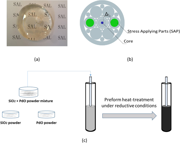
Figure 1. (a) Photograph of a bulk sample of SAL glass, (b) scheme of the fiber preform associating stack-and-draw and modified powder-in-tube technologies. The distance between the core and the SAP is noted Δ1, (c) illustration of the MPIT based process developed for fabricating preforms with Pd particles embedded into the cladding material.
Download figure:
Standard image High-resolution imageIn order to evaluate the contribution of Pd particles embedded into the SAPs, we have fabricated the same fiber preform without Pd particles in the SAPs, for obtaining a reference fiber that is named 'SAL-fiber' in the following. The preforms were drawn down to optical fibers with a drawing fiber tower. The scanning electron microscope (SEM) picture of the cross section of the SAL-fiber and of the fiber with Pd particles (named SALP-fiber) are shown in figures 2(a) and (b), respectively. Both fibers are composed of a Ge-doped core with a diameter of about 8 μm for ensuring single mode propagation in the spectral region around 1.55 μm. The diameter of the SAPs is about 24 μm and 21 μm for the SAL-fiber and SALP-fiber, respectively. It is worth noticing that the larger refractive index of SAL glass (than the silica one) requires to optically isolate the core and the SAPs by separating them by about 20 μm.

Figure 2. SEM (in the backscattered configuration) images of cross-sections of optical fibers fabricated by the MPIT process: (a) SAL fiber, (b) SALP fiber. (c) XRD diagram of Pd-based fiber of a heat-treated preform sample.
Download figure:
Standard image High-resolution imageX-ray powder diffraction (XRD) was performed on the SAPs of the SALP-fiber for estimating the oxidation state of Pd particles. As shown in figure 2(c), the diffraction peaks match with the database patterns of Pd (JCPDS n°46-1043) proving the reduction of PdO particles [13]. This measurement demonstrates the fabrication of an optical fiber with Pd particles embedded in the SAPs.
3. Experimental setup and methods
3.1. Birefringence measurements
We used the high birefringence fiber loop mirror (FLM) configuration for measuring the birefringence of the PM fiber. As illustrated in the schematic of the figure 3(a), this setup is composed of a sample of the PM fiber under-test, 3 dB fiber-coupler, an optical spectrum analyzer (OSA), and an optical broadband source. The incident light is splitted by the 3 dB coupler into two counter propagating beams that are recombined after propagating throughout the PM fiber. The birefringence of the PM fiber induces a phase difference between the two orthogonal beams that leads to an interference spectrum at the output of the FLM [16, 17]:

where B is the fiber birefringence and L the fiber length.
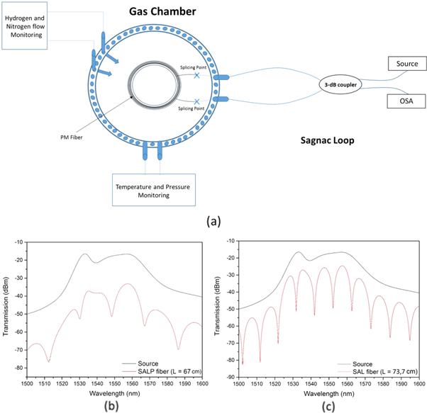
Figure 3. (a) Schematic of the hydrogenation setup. (b) Transmission spectra of the interferometer with SALP fiber with a length of 67 cm inside the FLM. (c) Transmission spectra of the interferometer with SAL fiber with a length of 73.7 cm inside the FLM.
Download figure:
Standard image High-resolution imageThis configuration presents many advantages such as a low sensitivity to external noise disturbances since both beams have the same optical path, a simple configuration that is easy to realize with all-fiber components, no dependence on polarization state of the input light. From relation (1), the birefringence (B) of the PM fiber is calculated by measuring the wavelength spacing between two consecutive transmission dips (Δλ) and the fiber length (L) with the following relation [16]:

where λ is the central wavelength (between two dips).
The dip wavelengths λ occur when  so that:

leading to:

where q is an integer,  and
and  the intial birefringence and wavelength of dip, and,
  the birefringence variation due to external perturbations such as temperature T and pressure P. These relations demonstrate that the relative wavelength sifth ([λ−λ0]/λ0) is independent to the fiber length and to the value of the initial wavelength (λ0). These behaviors are observable on the figures 4(a) and (b). The evolution of transmission spectrum of a FLM is identical for each transmission dip.

Figure 4. Spectrum shifts during N2-gas pressure and temperature sensitivity tests for the: (a) SALP optical fiber, (b) SAL optical fiber.
Download figure:
Standard image High-resolution imageThe transmission spectra of the FLM composed of 67 cm long length of SALP-fiber and of 73.7 cm long length of SAL-fiber are shown in figures 3(b) and (c), respectively. The mean birefringence of the SALP-fiber is about of 1.9 × 10⁻⁴ ± 0.1 × 10⁻⁴ and about 3.1 × 10⁻⁴ ± 0.1 × 10⁻⁴ for the SAL-fiber. These values were obtained by averaging the B values calculated for each Δλ of the spectra in figures 3(b) and (c). As demonstrated in [14], it is worth noticing that the birefringence is only induced by the SAP, since a similar fiber with empty SAPs (air holes) does not exhibit a measurable birefringence.
3.2. Hydrogenation bench for in-line measurements
We have specially developed a gas chamber for studying in real-time the impact of H2 gas (or other gas) on the optical properties of fiber samples. The chamber contains two channels for H2 gas and nitrogen (N2) gas flowing with controlled pressure and temperature. Four hermitic optical connectors enable to connect optical fibers or fiber-components inside the chamber to the interrogation setup for on-line measurements and dynamic comparisons between fiber samples or fiber-components. As illustrated in figure 3(a), the PM fiber under-test is inserted into the chamber and connected to the fiber-coupler of the FLM for enabling on-line measurement of the birefringence variation under H2 gas.
Before investigating the impact of H2 gas on the SALP-fiber, we have measured its sensitivity to the N2-gas pressure and to the temperature. SALP-fiber and SAL-fiber were both inserted in the chamber and connected to an FLM for comparing their sensitivities. The sensitivity to N2-gas pressure was studied by increasing the pressure of the gas into the chamber from 0 to 60 bar by steps of 20 bar. The temperature was set at 16 °C. As expected, the variation of the pressure yields a modification of the birefringence of both fibers leading to an evolution of the transmitted spectrum of each FLM (figures 4(a) and (b)). The variation of the birefringence (ΔB) induces a shift of the dip wavelengths λ and a modification of the spacing (Δλ) between each dips accordingly to ΔB. As shown theoretically in relation (3) and experimentally in figures 4(a) and (b), the spectral shift of a dip of the FLM spectrum is a relevant measure of the sensitivity of a PM fiber to the physical parameter considered. In the FLM configuration, the shift of a dip is only yielded by ΔB, independently to the length of the PM fiber, enabling direct comparison between different PM fibers without considering their length. It worth noticing that the length of the PM fiber affects only the bandwidth of the dips, which one could influence the uncertainty of the dip wavelength measurement.
As shown in figures 4(a) and 5(a), the transmission spectrum of the FLM shifts toward lower wavelengths when the pressure is increased. By measuring the wavelength shift of a dip for each pressure, we have calculated for the SALP fiber a wavelength dependency of −0.098 ± 0.03 nm bar−1, and a pressure sensitivity Sp = (1/λ0) (dλ/dP) of −6.2 × 10⁻⁵/bar with λ0 = 1558.25 nm the initial dip wavelength (at P = 0 bar). For the SAL-fiber, we have calculated a wavelength dependency of −0.064 ± 0.04 nm bar−1 and a pressure sensitivity Sp = −4.1 × 10⁻⁵/bar-1 with λ0 = 1570.8 nm. The wavelength shifts were measured when the temperature measured in the chamber (Tprocess) is stabilized, after the introduction of additional N2 gas.
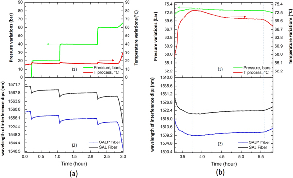
Figure 5. a(1) Pressure and Temperature variations for the pressure sensitivity test. a(2) Interference spectrum shift of the SAL (black curve) and SALP (blue curve) fiber. b(1) Pressure and temperature variations for the temperature sensitivity test. b(2) Interference spectrum shift of the SAL (black curve) and SALP (blue curve) fiber.
Download figure:
Standard image High-resolution imageThe sensitivity to the temperature was measured at an N2 pressure of 72.5 bar by decreasing the temperature from 72.5 °C to 69.6 °C leading to a shift of the transmission spectrum toward longer wavelengths (figure 5(b)). By linearly fitting the wavelength shift of a dip, we have calculated for the SALP fiber a wavelength dependency of −0.52 ± 0.05 nm °C−1, and a temperature sensitivity ST = (1/λ0) (dλ/dT) of −3.4 × 10⁻⁴ °C−1 with λ0 = 1522.54 nm. For the SAL-fiber, we have calculated a wavelength dependency of −0.53 ± 0.02 nm °C−1 and a temperature sensitivity ST = −3.5 × 10⁻⁴ °C-1 with λ0 = 1511.18 nm.
Both FLMs are sensitive to N2-gas pressure and the temperature variations confirming the interests of PM-fiber based FLM configurations for sensing applications [17]. Both fibers have the same temperature sensitivity (ST) and a similar pressure sensitivity (Sp) that is more than 5 times smaller than ST. These measurements demonstrate that Pd particles embedded in SAPs do not have a significant effect on the birefringence variations under pressure and/or temperature variations, and hence they will not induce parasitic variations on the birefringence (or wavelength dip) measurements during the diffusion of H2 gas into the fiber (at constant pressure and temperature).
4. Hydrogen sensing: experimental results and analysis
In order to evaluate the contribution of Pd particles embedded into an optical fiber for the detection of H2, both fiber samples (SALP and SAL) were inserted in the chamber and connected to FLMs for comparing their sensitivities. The chamber was initially filled during few hours with N2 gas (P = 20 bar at room temperature) to check the hermiticity of the chamber. N2 gas is then evacuated and replaced by the H2 gas with a pressure of 60 bar (figure 6). To accelerate the diffusion kinetics of H2 in the optical fiber, the temperature of the autoclave is increased to 70 °C. It is worth noticing that this temperature is in agreement with the repository conditions of radioactive wastes where the temperature could reach 90 °C in the repository cells for long-lived and high-level wastes. The pressure of H2 and temperature are kept constant during 123 h for enabling dynamic measures during the diffusion of H2 into the fibers. The gas is finally released and the temperature dropped down to room temperature.
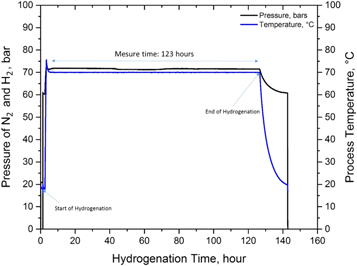
Figure 6. Hydrogenation protocol of the SAL and SALP optical fibers.
Download figure:
Standard image High-resolution imageWhen both fibers are exposed to H2 gas, the FLM spectra shift toward longer wavelengths (figure 7(a) and (b)). The dynamic of the wavelength shift of one dip of the spectrum is plotted in figure 7(c) for both fibers. These curves have been obtained by measuring the transmission spectrum of both FLMs each 2 min Both curves are plotted from 3.5 to 126.5 h for presenting only the impact of diffusion of H2 gas into the fibers. The variations of temperature and pressure yielded when H2 gas is introduced in the chamber are not presented. The diffusion of H2 gas induces a shift of the dips to longer wavelengths for both fibers, until a stabilization of the dip wavelengths corresponding to the saturation of H2 diffusion into the fiber core. More precisely, the shift of the dip wavelength reaches a maximum before its stabilization. As shown in figure 7(c) both curves have different behaviors. The maximum is reached after 20 h for the SALP-fiber, against 40 h for the SAL-fiber. Furthermore, at the maximum, the shift of wavelength dip of the SALP-fiber is 32% time larger than the shift at saturation, while it is only 6% for the SAL-fiber. These results demonstrate that Pd particles embedded in the SAP enhance the impact of H2 gas diffusion into the fiber on the birefringence properties.

Figure 7. The FLM spectra shift during hydrogenation of a (a) PANDA SALP optical fiber, (b) PANDA SAL optical fiber. (c) Wavelength shift of an interference dip of a PANDA SALP optical fiber (Red curve) and of a PANDA SAL optical fiber (Black curve) during hydrogenation. (d) Normalized birefringence changes (B/Bsaturation) a PANDA SALP optical fiber (Red curve) and of a PANDA SAL optical fiber (Black curve) during hydrogenation.
Download figure:
Standard image High-resolution imageThe variation of the birefringence is then calculated by equation (3), figure 7(d) represents the normalized birefringence (B/Bsaturation) for both fibers. These variations are similar to the ones of the dip wavelengths of both fibers. The SALP-fiber presents a stronger birefringence variation in comparison with the SAL-fiber, demonstrating the interests of the Pd particles.
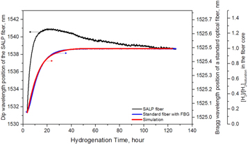
In order to evaluate the detection performances of the SALP fiber, we inserted into the gas chamber, a standard optical fiber (SMF28) composed of a Bragg grating written inside the core of the fiber. The shift of the Bragg wavelength as a function of the H2 diffusion time in the fiber is shown in blue in figure 8. We have also calculated, from an analytical model developed by Swart et al [18], the kinetic of H2 diffusion into the core of a standard optical fiber (red curve). The evolution of the concentration of H2 into the fiber core follows perfectly the shift of the Bragg wavelength. The diffusion of hydrogen into a standard silica-based singlemode fiber follows a cylindrical symmetry. Consequently, there is no induced birefringence but it yields a variation of the refractive index that can be captured by following the Bragg wavelength evolution of a fiber Bragg grating inscribed inside the core of the fiber. The evolution of the Bragg wavelength is thus representative of the variation of the concentration of H2 into the fiber core. The comparison between the shift of the Bragg wavelength and the wavelength shift of an interference dip of the SALP fiber shows different dynamics. As shown in figure 8, the shift of the dip wavelength of SALP fiber exhibits a faster response time and a larger amplitude. It is shifted by about 9 nm after 20 h of hydrogen diffusion, while it is shifted by less than 1 nm for the standard optical fiber. This comparison emphasises furthermore the interest of the SALP-fiber for detecting slow leakage of H2 gas with higher sensitivity and faster response time than the standard optical fiber.
Figure 8. Wavelength shift of an interference dip of a PANDA SALP optical fiber (Black curve) and of a standard optical fiber with Bragg grating written inside the core (blue curve) during hydrogenation. Simulations of the evolution of the hydrogen concentration in the center of a 125 μm optical fiber (Red curve).
Download figure:
Standard image High-resolution image
These results demonstrate the impact of Pd particles embedded in the SAPs on the optical properties of the SALP-fiber that are induced by the modifications of the strain field pattern (generated by the SAPs) during the diffusion of H2 gas into the fiber. Nevertheless, it would be interesting to study, the interplays between the variation of the strain field pattern during the diffusion of H2 gas and the diffusion kinetic of the gas into the SAPs composed or not of embedded Pd particles for both polarization axes of the fiber. This study might explain the faster response time of the SALP-fiber and even the SAL-fiber than the standard optical fiber, and also the maximum of the dip wavelength shift that is much higher for the SALP-fiber.
5. Conclusion
We have fabricated two disruptive birefringence optical fibers composed of two stress applying parts of SAL glass material with or without embedded Palladium particles. We have characterized these fibers and reported the first experimental study of the evolution of their birefringence during the diffusion of H2 gas into the fiber by inserting the fiber within a fiber loop mirror interferometer (FLM) associated with a specially developed gas chamber. On-line measurement dynamics and comparisons with the fiber without Pd particles demonstrate the contribution of Pd particles resulting in a faster response time. The maximum shift of the dip wavelengths (i.e. birefringence variation) of the FLM interferometer is reached after 20 h of hydrogenation (at 70 °C and 60 bar) while it requires 40 h for the reference fiber (SAL-fiber) and around 50 h for a standard optical fiber. These results pave the way to the realization of robust optical fiber with enhanced sensitivity to H2 gas for developing sensing systems compatible with long-term hydrogen monitoring applications in extreme and harsh environments, such as radioactive waste repositories.
Acknowledgments
The authors acknowledge financial support from the European project Modern2020, Euratom research and training program 2014–2018 under grant agreement No 662177. Also, the authors would like to thank the French National Radioactive Waste Management Agency (ANDRA) for their financial support.