Development of a Chemical Quasi-Equilibrium Model of Biomass Waste Gasification in a Fluidized-Bed Reactor by Using Aspen Plus


1
Department of Agricultural and Forestry Sciences (DAFNE), Tuscia University of Viterbo, Via San Camillo de Lellis, 01100 Viterbo, Italy
2
Department of Nuclear, Subnuclear and Radiation Physics, Marconi University, 00193 Rome, Italy
*
Author to whom correspondence should be addressed.
Energies 2020, 13(1), 53; https://doi.org/10.3390/en13010053
Submission received: 5 November 2019
/
Revised: 16 December 2019
/
Accepted: 17 December 2019
/
Published: 20 December 2019
(This article belongs to the Special Issue Hydrogen Production from Biomass)
Abstract
:In the delicate context of climate change, biomass gasification has been demonstrated to be a very useful technology to produce power and hydrogen. Nevertheless, in literature, there is a lack of a flexible and fast but accurate model of biomass gasification that can be used with all the combinations of oxidizing agents, taking into account both organic and inorganic contaminants, and able to give results that are more realistic. In order to do that, a model of biomass gasification has been developed using the chemical engineering software Aspen Plus. The developed model is based on the Gibbs free energy minimization applying the restricted quasi-equilibrium approach via Data-Fit regression from experimental data. The simulation results obtained, considering different mixes of gasifying agents, were compared and validated against experimental data reported in literature for the most advanced fluidized bed technology. The maximum discrepancy value obtained for hydrogen, with respect to experimental data, is of 8%, and all the other values reached by the developed simulations, considering both organic and inorganic compounds, are in good agreement with literature data. The gas yield reached by the developed simulation is in the range of 1.1–1.3 Nm3/kg.
1. Introduction
Every year, a great amount of agro-industrial, municipal and forestry residues are treated as waste; instead, they can be recovered and used to produce thermal and electrical energy by biological or thermo-chemical conversion processes [1,2]. Contrary to biological methods, thermo-chemical ones are more viable allowing the treatment of a wide range of feedstock in shorter residence time [3,4]. Among thermo-chemical processes, biomass gasification is one of the most efficacious conversion technologies because of lower investment costs while maintaining the ability for high-rate fuel gas production [5,6]. This process utilizes oxidizing agents (oxygen, air, steam or a mix of them) at high temperature (in the range of 750–1000 °C) to produce a fuel gas, called syngas, mostly rich in hydrogen, carbon monoxide, carbon dioxide, methane and steam along with several unwanted by-products [3]. A good quality syngas is characterized by low level of N2, high level of H2, low level of contaminants and high heating values (LHV) [7,8]. Further studies have demonstrated that the fluidized-bed is a promising type of gasifier, which ensures high reaction rates and conversion efficiencies thanks to good mixing and gas-solid contact [9,10]. Process and system simulation models have obtained great interest in the prediction of performance, giving a good description of both chemical and physical phenomena occurring into the gasifier and allowing to assess the plant behavior with the purpose of optimizing the gasifier design and its operation with minimal time and costs [11]. Among the system simulators which can be used in simulating thermochemical plants, Aspen Plus represents one of the most powerful and versatile options [11,12,13]. Developed by Massachusetts Institute of Technology (MIT), Aspen Plus is a chemical engineering process optimization software that utilizes unit operation blocks, such as reactors, pumps, columns, heat exchangers, etc. Each unit block is linked to another by material and energy streams to create a flow sheet for the whole process. The program is based on a sub-sequential modular approach, and the simulation calculations use the in-built physical properties database [14]. Several authors investigated biomass-gasification process by using Aspen Plus. Different approaches can be used, among them, kinetic and equilibrium models are the most used [12,15]. Kinetic models can be used to predict syngas yield, the products of syngas composition achieved by a gasifier after a finite time (or in a finite volume in a flowing medium), profile of temperature inside the reactor and the gasifier performance for a stabilized operating condition and gasifier configuration [16,17]. In order to do that, kinetic models consider the kinetics of the gasification reactions and the hydrodynamics of the gasifier. Thus, these models contain parameters that can restrict their applicability to specific plants; moreover, increasing the complexity in the design of the gasifier, the complexity of the model increases since the model is based on reactor hydrodynamics.
The thermodynamic equilibrium model allows to predict the syngas composition based on the assumption that the reactants react in a fully mixed condition for an infinite time [18]. This model is independent of the gasifier design and so it may be more suitable for process studies on the influence of the different process parameters. Then, equilibrium models are divided into two sub-categories: stoichiometric models and non-stoichiometric ones. Stoichiometric models are based on equilibrium constants, so they need specific chemical reactions involved in the process. Non-stoichiometric models are based on minimization of the Gibbs free energy, and they offer the advantage of not considering the chemical reactions. The equilibrium models have been used successfully by many researchers in modelling the gasification process in fluidized-bed gasifiers [5,6,12,19], allowing to evaluate the effect of temperature of reactor, equivalence ratio, steam to biomass ratio and moisture content of feedstock on the gasification process. An upgrade of the non-stoichiometric equilibrium model is the quasi-equilibrium approach, which is a compromise between equilibrium thermodynamic models and experimental ones and does not require specific information on the dimensions, capacity and structure of the reactor. This approach gives a more accurate description of the syngas composition and is considered one of the most effective ways to simulate the performance of a gasifier [14]. The first one who introduced the quasi-equilibrium model was Gumz [20], who proposed to use the QET (Quasi-Equilibrium Temperature), that is, the temperature at which the chemical reaction is considered to have reached equilibrium, rather than the actual temperature of the gasifier. In order to evaluate the QET, a Data-Fit made by experimental data can be used. Nevertheless, even if some QET models for fluidized bed gasifiers are present in literature, there is a lack of QET models that encompass air/steam/oxygen gasification and form inorganic (hydrogen sulphide, hydrogen chloride and ammonia) and organic (toluene, benzene and naphthalene) products. Arteaga-Pèrez et al. [21] developed a quasi-equilibrium biomass gasification system by means of Aspen Plus. The gas composition out of the gasifier was corroborated with the experimental data in a bubble fluidized-bed pilot scale. The parameters that varied during the case studies were the gasifier temperature and the air factor. It was found that the maximum yield of syngas is achieved at 850 °C and at air equivalent ratio (ER) equal to 0.3. The unique contaminant compound considered by Arteaga-Pèrez et al. was naphthalene, and the only oxidizing agent was air. Mirmoshtaghi et al. [22] developed a model for biomass gasification in a fluidized-bed gasifiers with QET by using Aspen Plus, predicting the content (volume fraction) of the four major components (H2, CO, CO2 and CH4) in product gas and not considering any kind of contaminants. The oxidizing agent was only air. The temperature range of the gasification was set to 730–815 °C, and the ER was between 0.22 and 0.53.
In the present work, the authors have developed, and validated against experimental data, a quasi-equilibrium model of air/steam/oxygen biomass-gasification that includes organic and inorganic products. In this way the model is able to predict syngas composition and contaminants, and the authors have evaluated the effect of several variables including gasification temperature and steam to biomass ratio (S/B) on the gas composition for different gasifying agents.
2. Materials and Methods
2.1. Biomass Characteristics
Using biomass waste from agricultural means zero costs for the feedstock, avoiding fuel vs. food competition and having less life cycle impacts. In order to select the most suitable biomass waste to feed the gasifier, the following criteria have to be taken into account [1]:
- Availability of biomass on a significant scale (tons/year);
- Low heat value (LHV), which has to be high, so biomass with lower humidity is preferable;
- Chemical composition, which has to be low in sulfur, chlorine and ash;
- Size and shape of biomass, which have to be uniform in order to ensure homogeneous and efficient gasification and bulk density, which has to be comparable with that of the gasifier bed, even if the latter can be adjusted via pretreatment and feeding systems.
2.2. Aspen Plus Modelling
The simulation of the biomass gasification process, carried out on Aspen Plus, is based on mass-energy balance and chemical equilibrium among all processes. The following assumptions were considered for the simulation:
- Process is steady state and isothermal [26];
- Drying and pyrolysis happen instantaneously, and volatile products principally consist of H2, CO, CO2, CH4 and H2O [27];
- Char is 100% carbon [28];
- All gases behave ideally;
- The tars considered are toluene (1-ring), naphthalene (2-ring) and benzene;
- The inorganic contaminants considered are hydrogen sulphide, hydrogen chloride and ammonia.
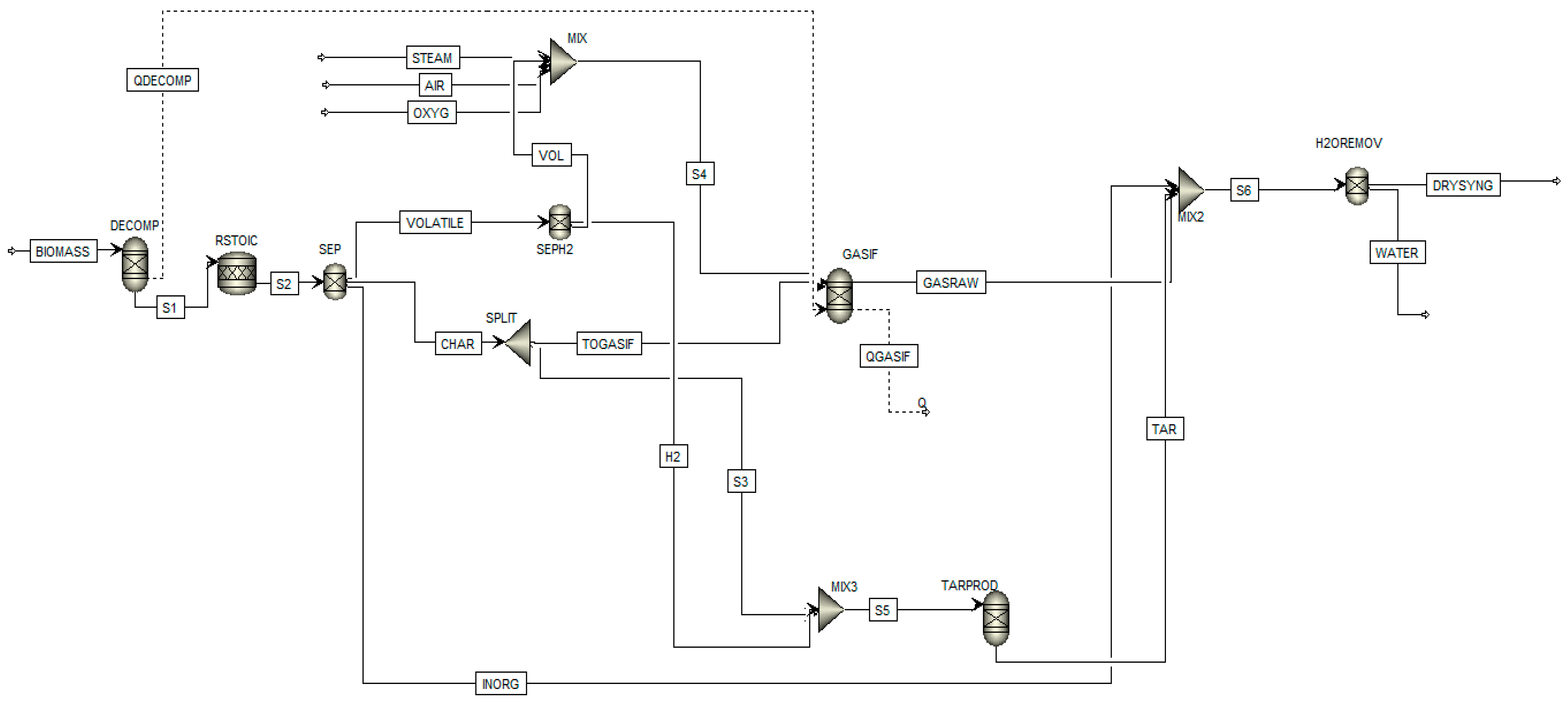
The Aspen Plus flow sheet of the developed model is shown in Figure 1 while all the units are described in Table 2.
In this simulation, the biomass is defined as a nonconventional component, its ultimate and proximate analyses specified according to Table 1. The Peng–Robinson equation with Boston–Mathias (PR-MB) modification, has been used to evaluate all physical properties of the conventional components in the gasification process. HCOALGEN and DCOALGEN models are selected for the evaluation of the enthalpy and density of both biomass and ash, which are non-conventional components.
2.3. Description of Aspen Plus Flow-Sheet
The power plant is mostly composed of a gasification reactor producing hazelnut shell-derived syngas. The stream BIOMASS, representing the hazelnut shell feed, goes firstly in the DECOMP block that is a RYield reactor, used to simulate the decomposition of the unconventional feed into its conventional components (carbon, hydrogen, oxygen, sulfur, nitrogen and ash, by specifying the yield distribution according to the biomass ultimate analysis in Table 1). Considering that the DECOMP block creates N, Cl and S as elemental components, which are known to produce principally HCl, NH3 and H2S, and the results of experimental fractional conversion model are closer to the experimental data with respect to restricted chemical equilibrium, the product out of DECOMP is moved to the RStoic block to simulate the production of H2S, HCl and NH3 by the following reactions [5]:
- H2 + S → H2S (R1)
- Cl2 + H2 → 2HCl (R2)
- 0.5N2 + 1.5 H2 → NH3 (R3)
The fractional conversion considered for S, Cl2 and N2 is equal to 1 [12]. Deriving stream S2 goes into a separator SEP, which separates the stream S2 in three sub-streams: Volatile part VOLATILE, char part CHAR and a stream composed by HCl, NH3 and H2S, called INORG. Then, VOLATILE stream is divided in two sub-streams: VOL and H2; the former, after mixing with the oxidizing fluid, goes into the gasifier, GASIF, and the latter is used to simulate tar production in the RYield block TARPROD;. The block TARPROD is necessary since we are in steady-state conditions, and it is not possible to simulate tar formation inside the gasifier GASIF. CHAR stream is split in two sub-streams: TOGASIF that represents the char reacted in the gasifier and S3 that represents the un-reacted char; the latter is then fed to TARPROD where it reacts with hydrogen from the H2 stream. The tar is assumed to be a formation of toluene, benzene and naphthalene. The quantities of these tars are set in accordance with literature [29] and proportions of about 60%, 20% and 20% for benzene, toluene and naphthalene, respectively, are maintained [30]. The stream S6 is the stream that represents the real output of the gasifier; in fact, it is made of the union of GASRAW, INORG and TAR streams.
2.4. Gasification Model
The reactions considered in the gasification process are reported in Table 3.
Equations (R4) to (R8) of Table 3 are the chemical reactions considered in this work for the gasification process where the oxygen comes from biomass composition, as showed in ultimate analysis, and from air/oxygen stream if air/oxygen gasification is considered. To simulate the gasification process on Aspen Plus, a RGibbs reactor, called GASIF in Figure 1, has been used. This reactor was modelled with the restricted quasi-equilibrium approach, which allows to describe syngas composition more accurately than equilibrium models, as explained in the Introduction. Therefore, the reactions within the reactor (listed in Table 3) are conducted at their QET, rather than at the actual temperature of the gasifier. In order to be more rigorous, a Data Fit of experimental data (about hazelnut or almond shells, since they have very similar characteristics [5], using steam and/or oxygen or air as gasification agent with a gasification temperature from 600 °C to 870 °C and S/B from 0.33 to 1) has been implemented on Aspen Plus (Table 4). In this way, RGibbs gasifier evaluates the chemical equilibrium constant for each reaction at the gasifier temperature, and by that, it provides the equilibrium syngas composition. Since the Data-Fit was made from literature data obtained from experiment carried out with several gasifying agents (steam, air, oxygen or a mix of these) and silica sand as bad material, the model can simulate almost all oxidizing gasification agents (i.e., CO2 excluded).
3. Results and Discussions
In order to demonstrate the feasibility of the developed model with different mix of oxidizing agents, several comparisons with experimental data have been conducted. The comparisons showed that the results predicted by the model are reasonable and near to the real ones.
3.1. Steam Gasification Results and Model Validation
The developed simulation model has been validated using experimental data of Rapagnà and Latif [32] and Karatas and Akgun [38] for steam gasification. Rapagnà and Latif used a lab-scale fluidized-bed reactor as gasifier, at 1 bar and 800 °C and hazelnut shells as biomass feedstock. The lab-scale reactor used by Karatas and Akgun was a fluidized-bed, at 1 bar and 800 °C, and the biomass feedstock used was walnut shells, which have very similar characteristics with respect to hazelnut shells. The comparison of the operative conditions and results of the present model simulation and literature data are reported in Table 5. The discrepancy of the simulative results against experimental values is shown in Table 6.
The comparison of the resulting composition values with the literature ones, reported in Table 5, shows a comparable product syngas composition (the difference is below 10% for the main gas, i.e., H2, below 38% for CO and CO2 and below 15% for CH4). The under or the over prediction of CH4 is an ordinary issue in the simulative modelling since tar is not considered in the equilibrium models and it is simulated apart from the gasifier block. The underproduction of CO and the overproduction of CO2 might be caused by the fact that the steam kinetic factors were not taken into account in the simulation. Indeed, steam lowers the gas speed and thus causes an increase in residence time and favors the dissociation of H2O. Therefore, the conversion of char and heavy hydrocarbons into light ones (i.e., CO) was favored. The production of tar and inorganic contaminants is not evaluated by Rapagnà and Latif and Karatas and Akgun; however, the results obtained for toluene, benzene and naphthalene agree with other literature experimental sources [25,29,39]. Zhou et al. reported that the concentration of NH3 in the gasification product is between 500 to 30,000 ppm, depending on the nitrogen content of the biomass feedstock and the gasifier conditions [40]. The concentration of H2S reported in literature ranges from 1000 to 14,000 ppm in the raw syngas [41], and the concentration of HCl is around 750 ppm [41].
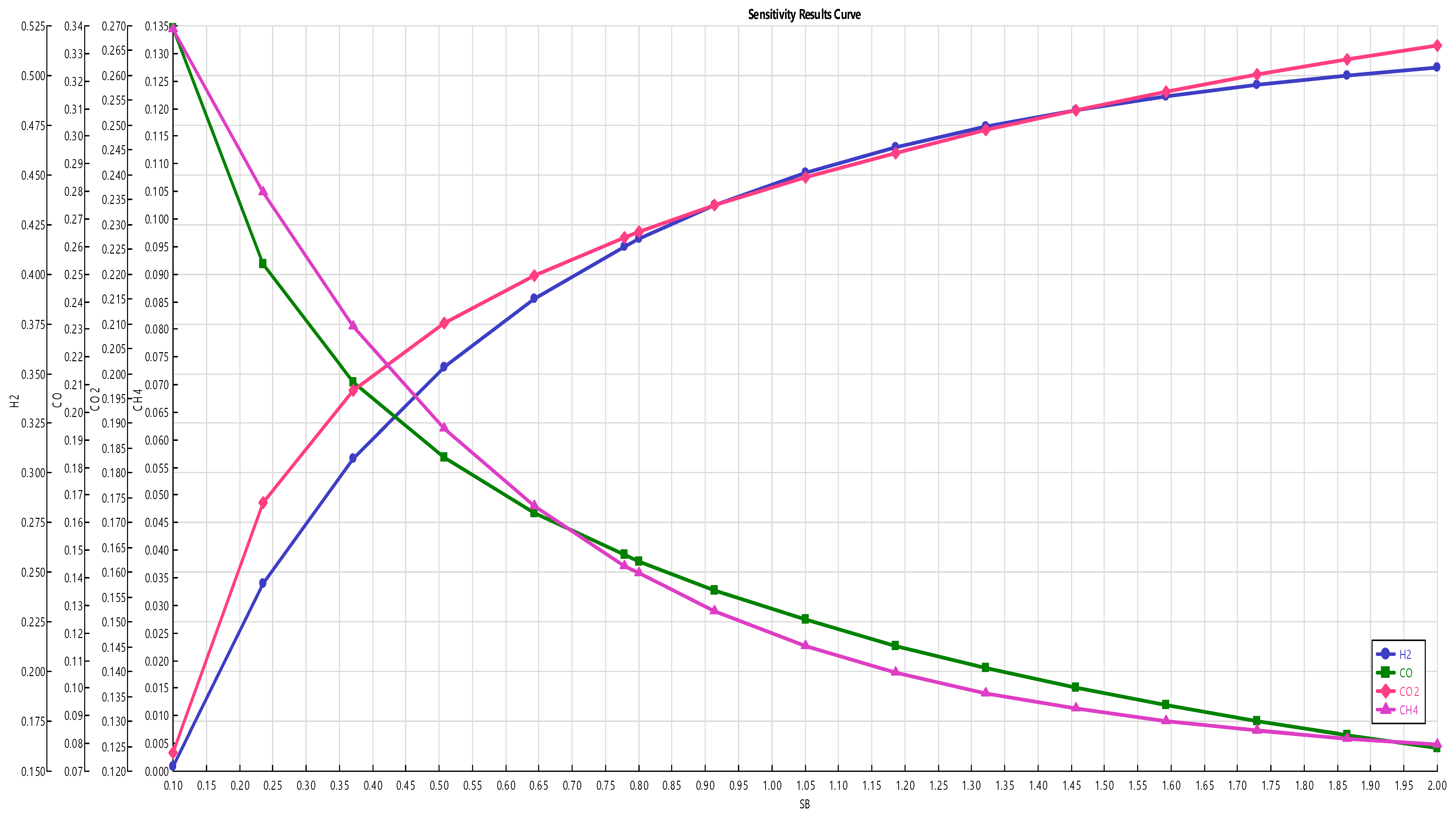
3.2. Effect of Steam to Biomass (S/B) Ratio
A sensitivity analysis is carried out in order to evaluate the effect of the S/B ratio on the hazelnut shell-derived syngas composition that comes from the gasifier at the fixed temperature of 800 °C. In Figure 2, the trend of the dry molar fraction of each component is reported against S/B ratio. The concentration of H2 and CO2 rises with the rise of S/B ratio, and the concentrations of CO and CH4 decrease with S/B ratio. Increasing steam favors the water-gas reaction and steam methane reforming reactions resulting in an increase of H2 and CO concentrations; however, the CO concentration decreases with increasing S/B ratio due to the water-gas shift reaction, which reduces CO reacting with steam and increases H2 and CO2 concentrations. Similar trends were reported in literature references [42,43].
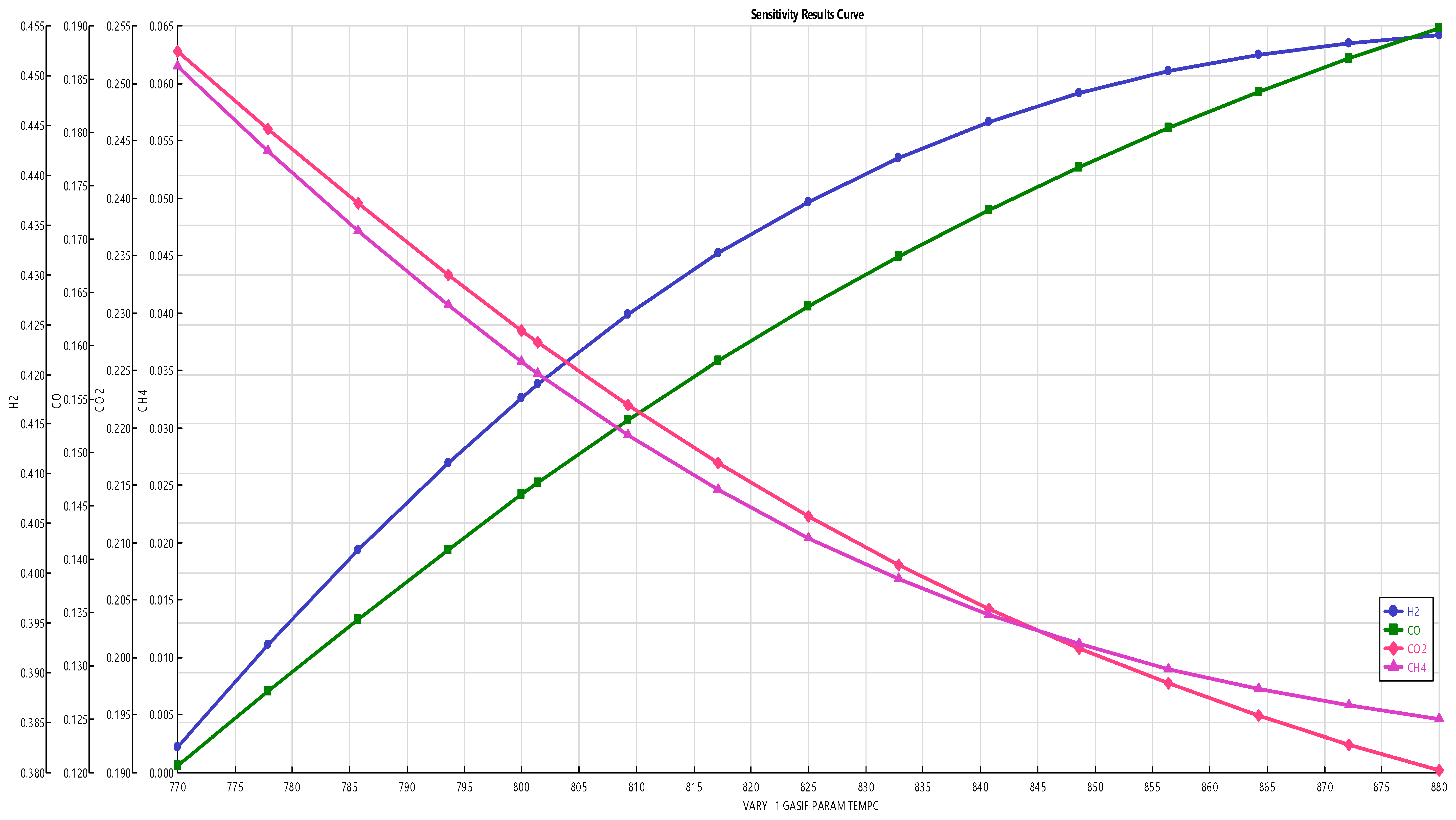
3.3. Effect of Gasification Temperature on Syngas Composition
A sensitivity analysis is carried out in order to evaluate the effect of the gasification temperature on the hazelnut shells-derived syngas composition, keeping the S/B ratio fixed at 0.8. In Figure 3, the trend of the syngas composition as a function of the temperature in the range 770–880 °C is shown. It can be observed that H2 and CO concentrations increase with the increase of temperature, due to the endothermic reactions R5 (water–gas) and R8 (steam methane reforming). On the other hand, the increase of temperature causes the decrease of CO2, CH4 and H2O. The decrease of CO2 production depends on reaction R7 (water–gas shift) that is exothermic, being favored at low temperatures, and for this reason, the higher temperature means higher CO and lower CO2 production. Similar trends were observed by [5,44].
3.4. Air-Steam Gasification Results and Model Validation
The developed simulation model has been validated using experimental data of Lv et al. [45] for air-steam gasification. The experimental set-up was a fluidized-bed reactor, operated at 1 bar and 800 °C, and the biomass feedstock used was pine sawdust, which presents very similar characteristics with respect to hazelnut shells, except for the inorganics that are not considered. The comparison of the operative conditions and results of the present model simulation and literature data are reported in Table 7. The discrepancy of the simulative results against experimental values is shown in Table 8.
The comparison of the resulting composition values with the literature ones, reported in Table 7, shows a comparable product syngas composition (the difference is 6% for the main gas, i.e., H2, below 18% for CO and CO2 and 80% for CH4, but it has already been mentioned previously that CH4 is under- or over-predicted). Tar production was not evaluated by Lv et al., but as for the case mentioned previously in the text, the results obtained for toluene, benzene and naphthalene agree with other literature experimental sources [25,29,39], and the same goes for the inorganic compounds’ concentration.
3.5. Steam-Oxygen Gasification Results and Model Validation
Experimental data is rarer regarding steam-oxygen; therefore, the developed simulation model has been validated using experimental data of Barisano et al. [46] for steam-oxygen gasification that used olivine instead of silica sand as bed material and almond instead of hazelnut shells as biomass. Almond shells have very similar characteristics respect to the hazelnut shells, and the olivine is well known to have a WGS catalyst effect (so the H2 and CO2 contents will be higher meanwhile CO lower). The experimental set-up used by Barisano et al. was a fluidized-bed reactor, worked at 1 bar and 850 °C. The comparison of the operative conditions and results of the present model simulation and literature data are reported in Table 9. The discrepancy of the simulative results against experimental values is shown in Table 10.
The comparison of the resulting composition values with the literature ones, reported in Table 9, shows a comparable product syngas composition (the difference is 16% for the main gas, i.e., H2, below 16% for CO and CO2 and 58% for CH4, but it has already been mentioned previously that CH4 is under- or over-predicted). Thus, even if olivine was used as bed material, the difference of H2, CO and CO2 are similar to the previous ones. Tar production was not evaluated by Barisano et al., but as for the case mentioned previously in the text, the results obtained for toluene, benzene and naphthalene agree with other literature experimental sources [25,29,46] and the same goes for the inorganic contaminants concentration.
4. Conclusions
In the last decades, biomass gasification technology has been established as a viable technique for the conversion of many solid biomass residues in valuable syngas that can generate electricity and heat via cogeneration devices such as combustion engines, turbines or fuel cells or produce biofuels or chemicals. In order to optimize gasifier design and its operation with minimal time and costs, models that do not require specific information on the dimensions, capacity and structure of the reactor but that at the same time can give accurate descriptions of syngas composition are needed. Quasi-equilibrium temperature models seem to provide an answer to this problem, but there is no model in literature that encompasses air/steam/oxygen gasification including inorganic (hydrogen sulphide, hydrogen chloride and ammonia) and organic (toluene, benzene and naphthalene) contaminants. In order to develop a model that can be applied to almost all the combinations of oxidizing agents, a Data-Fit of experimental data carried out with several gasifying agents (steam, air, oxygen or a mix of these) has been taken from literature. The model has been validated using the most abundant lignocellulosic waste (here hazelnut shell) and the most used oxidizing agents (S/B ratio at 0.4 and 0.8; steam at 0.5 and ER at 0.2; S/B ratio at 0.4 and oxygen to biomass ratio at 0.36) showing good correlation between simulative and experimental data. The maximum value of discrepancy for the hydrogen concentration, which is the main component of the gasification gas, is of 16.3%. Moreover, the sensitivity analysis has showed similar trends to the ones reported in literature. Thus, the model can be used to simulate composition and contaminants of different gasification processes without taking into account specific information on the dimensions, capacity and structure of the reactor but, nevertheless, being able to have results not too different from experimental ones.
Author Contributions
Conceptualization, E.B.; methodology, V.M., E.B.; software, V.M.; validation, V.M., E.B.; resources, E.B.; data curation, V.M.; writing—original draft preparation, V.M.; writing—review and editing, V.M., E.B. and D.M.; supervision, E.B. and D.M.; project administration, E.B.; funding acquisition, E.B. All authors have read and agreed to the published version of the manuscript.
Funding
This research was founded by the European Union’s Horizon 2020 research and innovation program under grant agreement No. 815284.
Conflicts of Interest
The authors declare no conflict of interest.
References
- Villarini, M.; Marcantonio, V.; Colantoni, A.; Bocci, E.; Villarini, M.; Marcantonio, V.; Colantoni, A.; Bocci, E. Sensitivity Analysis of Different Parameters on the Performance of a CHP Internal Combustion Engine System Fed by a Biomass Waste Gasifier. Energies 2019, 12, 688. [Google Scholar] [CrossRef] [Green Version]
- Colantoni, A.; Villarini, M.; Marcantonio, V.; Gallucci, F.; Cecchini, M. Performance Analysis of a Small-Scale ORC Trigeneration System Powered by the Combustion of Olive Pomace. Energies 2019, 12, 2279. [Google Scholar] [CrossRef] [Green Version]
- Qi, T.; Lei, T.; Yan, B.; Chen, G.; Li, Z.; Fatehi, H.; Wang, Z.; Bai, X.-S. Biomass Steam Gasification in Bubbling Fluidized Bed for Higher-H2 Syngas: CFD Simulation with Coarse Grain Model. Int. J. Hydrog. Energy 2019, 44, 6448–6460. [Google Scholar] [CrossRef]
- Tian, T.; Li, Q.; He, R.; Tan, Z.; Zhang, Y. Effects of Biochemical Composition on Hydrogen Production by Biomass Gasification. Int. J. Hydrog. Energy 2017, 42, 19723–19732. [Google Scholar] [CrossRef]
- Marcantonio, V.; De Falco, M.; Capocelli, M.; Bocci, E.; Colantoni, A.; Villarini, M. Process Analysis of Hydrogen Production from Biomass Gasification in Fluidized Bed Reactor with Different Separation Systems. Int. J. Hydrog. Energy 2019, 44, 10350–10360. [Google Scholar] [CrossRef]
- Li, X.T.; Grace, J.R.; Lim, C.J.; Watkinson, A.P.; Chen, H.P.; Kim, J.R. Biomass Gasification in a Circulating Fluidized Bed. Biomass Bioenergy 2004, 26, 171–193. [Google Scholar] [CrossRef]
- Fremaux, S.; Beheshti, S.-M.; Ghassemi, H.; Shahsavan-Markadeh, R. An Experimental Study on Hydrogen-Rich Gas Production via Steam Gasification of Biomass in a Research-Scale Fluidized Bed. Energy Convers. Manag. 2015, 91, 427–432. [Google Scholar] [CrossRef]
- Ngoc Lan Thao, N.T.; Chiang, K.-Y.; Wan, H.-P.; Hung, W.-C.; Liu, C.-F. Enhanced Trace Pollutants Removal Efficiency and Hydrogen Production in Rice Straw Gasification Using Hot Gas Cleaning System. Int. J. Hydrog. Energy 2019, 44, 3363–3372. [Google Scholar] [CrossRef]
- Puig-Arnavat, M.; Bruno, J.C.; Coronas, A. Review and Analysis of Biomass Gasification Models. Renew. Sustain. Energy Rev. 2010, 14, 2841–2851. [Google Scholar] [CrossRef]
- An, H.; Song, T.; Shen, L.; Qin, C.; Yin, J.; Feng, B. Coal Gasification with in Situ CO2 Capture by the Synthetic CaO Sorbent in a 1 KWth Dual Fluidised-Bed Reactor. Int. J. Hydrog. Energy 2012, 37, 14195–14204. [Google Scholar] [CrossRef]
- Ahmed, T.Y.; Ahmad, M.M.; Yusup, S.; Inayat, A.; Khan, Z. Mathematical and Computational Approaches for Design of Biomass Gasification for Hydrogen Production: A Review. Renew. Sustain. Energy Rev. 2012, 16, 2304–2315. [Google Scholar] [CrossRef]
- Doherty, W.; Reynolds, A.; Kennedy, D. Aspen plus simulation of biomass gasification in a steam blown dual fluidised bed; Book Chapter: Materials and processes for energy: communicating current research and technological developments; Méndez-Vilas, A., Ed.; Formatex Research Centre: Badajoz, Spain, 2013. [Google Scholar]
- Pala, L.P.R.; Wang, Q.; Kolb, G.; Hessel, V. Steam Gasification of Biomass with Subsequent Syngas Adjustment Using Shift Reaction for Syngas Production: An Aspen Plus Model. Renew. Energy 2017, 101, 484–492. [Google Scholar] [CrossRef]
- Patra, T.K.; Sheth, P.N. Biomass Gasification Models for Downdraft Gasifier: A State-of-the-Art Review. Renew. Sustain. Energy Rev. 2015, 50, 583–593. [Google Scholar] [CrossRef]
- Nikoo, M.B.; Mahinpey, N. Simulation of Biomass Gasification in Fluidized Bed Reactor Using ASPEN PLUS. Biomass Bioenergy 2008, 32, 1245–1254. [Google Scholar] [CrossRef]
- Basu, P. Biomass Gasification and Pyrolysis: Practical Design and Theory; Academic Press: Burlington, MA, USA, 2010. [Google Scholar]
- Ahmed, A.M.A.; Salmiaton, A.; Choong, T.S.Y.; Azlina, W.W. Review of Kinetic and Equilibrium Concepts for Biomass Tar Modeling by Using Aspen Plus. Renew. Sustain. Energy Rev. 2015, 52, 1623–1644. [Google Scholar] [CrossRef]
- Baruah, D.; Baruah, D.C. Modeling of Biomass Gasification: A Review. Renew. Sustain. Energy Rev. 2014, 39, 806–815. [Google Scholar] [CrossRef]
- Paviet, F.; Chazarenc, F.; Tazerout, M. Thermo Chemical Equilibrium Modelling of a Biomass Gasifying Process Using ASPEN PLUS. Int. J. Chem. React. Eng. 2019, 7. Available online: https://www.researchgate.net/publication/245418963_Thermo_Chemical_Equilibrium_Modelling_of_a_Biomass_Gasifying_Process_Using_ASPEN_PLUS (accessed on 19 December 2019). [CrossRef]
- Gumz, W. Gas Producers and Blast Furnaces; John Wiley & Sons: Hoboken, NJ, USA, 1950. [Google Scholar]
- Arteaga-Pérez, L.E.; Casas-Ledón, Y.; Pérez-Bermúdez, R.; Peralta, L.M.; Dewulf, J.; Prins, W. Energy and Exergy Analysis of a Sugar Cane Bagasse Gasifier Integrated to a Solid Oxide Fuel Cell Based on a Quasi-Equilibrium Approach. Chem. Eng. J. 2013, 228, 1121–1132. [Google Scholar] [CrossRef]
- Mirmoshtaghi, G.; Li, H.; Thorin, E.; Dahlquist, E. Evaluation of Different Biomass Gasification Modeling Approaches for Fluidized Bed Gasifiers. Biomass Bioenergy 2016, 91, 69–82. [Google Scholar] [CrossRef]
- Monarca, D.; Colantoni, A.; Cecchini, M.; Longo, L.; Vecchione, L.; Carlini, M.; Manzo, A. Energy Characterization and Gasification of Biomass Derived by Hazelnut Cultivation: Analysis of Produced Syngas by Gas Chromatography. Math. Probl. Eng. 2012, 2012, 1–9. [Google Scholar] [CrossRef] [Green Version]
- Monarca, D.; Cecchini, M.; Guerrieri, M.; Colantoni, A. Conventional And Alternative Use Of Biomasses Derived By Hazelnut Cultivation And Processing. Acta Hortic. 2009, 845, 627–634. [Google Scholar] [CrossRef]
- Di Carlo, A.; Borello, D.; Sisinni, M.; Savuto, E.; Venturini, P.; Bocci, E.; Kuramoto, K. Reforming of Tar Contained in a Raw Fuel Gas from Biomass Gasification Using Nickel-Mayenite Catalyst. Int. J. Hydrog. Energy 2015, 40, 9088–9095. [Google Scholar] [CrossRef]
- Ye, G.; Xie, D.; Qiao, W.; Grace, J.R.; Lim, C.J. Modeling of Fluidized Bed Membrane Reactors for Hydrogen Production from Steam Methane Reforming with Aspen Plus. Int. J. Hydrog. Energy 2009, 34, 4755–4762. [Google Scholar] [CrossRef]
- Sadaka, S.S.; Ghaly, A.E.; Sabbah, M.A. Two Phase Biomass Air-Steam Gasification Model for Fluidized Bed Reactors: Part I—Model Development. Biomass Bioenergy 2002, 22, 439–462. [Google Scholar] [CrossRef]
- Demirbaş, A. Carbonization Ranking of Selected Biomass for Charcoal, Liquid and Gaseous Products. Energy Convers. Manag. 2001, 42, 1229–1238. [Google Scholar] [CrossRef]
- Rapagnà, S.; Orazio, A.D.; Gallucci, K.; Ugo, P. Hydrogen Rich Gas from Catalytic Steam Gasification of Biomass in a Fluidized Bed Containing Catalytic Filters. Chem. Eng. Trans. 2014, 37, 157–162. [Google Scholar]
- Damartzis, T.; Michailos, S.; Zabaniotou, A. Energetic Assessment of a Combined Heat and Power Integrated Biomass Gasification-Internal Combustion Engine System by Using Aspen Plus®. Fuel Process. Technol. 2012, 95, 37–44. [Google Scholar] [CrossRef]
- Koppatz, S.; Pfeifer, C.; Hofbauer, H. Comparison of the performance behaviour of silica sand and olivine in a dual fluidised bed reactor system for steam gasification of biomass at pilot plant scale. Chem. Eng. J. 2011, 175, 468–483. [Google Scholar] [CrossRef]
- Serigio, R.; Ajmal, L. Steam Gasification of Almond Shells in a Fluidised Bed Reactor: The Influence of Temperature and Particle Size on Product Yield and Distribution. Biomass Bioenergy 1997, 12, 281–288. [Google Scholar]
- Karatas, H.; Olgun, H.; Akgun, F. Experimental Results of Gasification of Cotton Stalk and Hazelnut Shell in a Bubbling Fluidized Bed Gasifier under Air and Steam Atmospheres. Fuel 2013, 112, 494–501. [Google Scholar] [CrossRef]
- Barisano, D.; Canneto, G.; Nanna, F.; Villone, A.; Alvino, E.; Carnevale, M.; Pinto, G. Production of Gaseous Carriers via Biomass Gasification for Energy Purposes. Energy Procedia 2014, 45, 2–11. [Google Scholar] [CrossRef] [Green Version]
- Rapagnà, S.; Jand, N.; Kiennemann, A.; Foscolo, P.U. Steam-Gasification of Biomass in a Fluidised-Bed of Olivine Particles. Biomass Bioenergy 2000, 19, 187–197. [Google Scholar] [CrossRef]
- Esfahani, R.M.; Wan Ab Karim Ghani, W.A.; Mohd Salleh, M.A.; Ali, S. Hydrogen-Rich Gas Production from Palm Kernel Shell by Applying Air Gasification in Fluidized Bed Reactor. Energy Fuels 2012, 26, 1185–1191. [Google Scholar] [CrossRef]
- Barisano, D.; Canneto, G.; Nanna, F.; Alvino, E.; Pinto, G.; Villone, A.; Carnevale, M.; Valerio, V.; Battafarano, A.; Braccio, G. Steam/Oxygen Biomass Gasification at Pilot Scale in an Internally Circulating Bubbling Fluidized Bed Reactor. Fuel Process. Technol. 2016, 141, 74–81. [Google Scholar] [CrossRef]
- Karatas, H.; Akgun, F. Experimental Results of Gasification of Walnut Shell and Pistachio Shell in a Bubbling Fluidized Bed Gasifier under Air and Steam Atmospheres. Fuel 2018, 214, 285–292. [Google Scholar] [CrossRef]
- Savuto, E.; Di Carlo, A.; Bocci, E.; D’Orazio, A.; Villarini, M.; Carlini, M.; Foscolo, P.U. Development of a CFD Model for the Simulation of Tar and Methane Steam Reforming through a Ceramic Catalytic Filter. Int. J. Hydrog. Energy 2015, 40, 7991–8004. [Google Scholar] [CrossRef]
- Zhou, L.; Yang, Z.; Tang, A.; Huang, H.; Wei, D.; Yu, E.; Lu, W. Steam-Gasification of Biomass with CaO as Catalyst for Hydrogen-Rich Syngas Production. J. Energy Inst. 2019, 92, 1641–1646. [Google Scholar] [CrossRef]
- Dou, B.; Wang, C.; Chen, H.; Song, Y.; Xie, B.; Xu, Y.; Tan, C. Research Progress of Hot Gas Filtration, Desulphurization and HCl Removal in Coal-Derived Fuel Gas: A Review. Chem. Eng. Res. Des. 2012, 90, 1901–1917. [Google Scholar] [CrossRef]
- Florin, N.H.; Harris, A.T. Hydrogen Production from Biomass Coupled with Carbon Dioxide Capture: The Implications of Thermodynamic Equilibrium. Int. J. Hydrog. Energy 2007, 32, 4119–4134. [Google Scholar] [CrossRef]
- Inayat, A.; Ahmad, M.M.; Yusup, S.; Mutalib, M.I.A.; Inayat, A.; Ahmad, M.M.; Yusup, S.; Mutalib, M.I.A. Biomass Steam Gasification with In-Situ CO2 Capture for Enriched Hydrogen Gas Production: A Reaction Kinetics Modelling Approach. Energies 2010, 3, 1472–1484. [Google Scholar] [CrossRef] [Green Version]
- Puig-Gamero, M.; Argudo-Santamaria, J.; Valverde, J.L.; Sánchez, P.; Sanchez-Silva, L. Three Integrated Process Simulation Using Aspen Plus®: Pine Gasification, Syngas Cleaning and Methanol Synthesis. Energy Convers. Manag. 2018, 177, 416–427. [Google Scholar] [CrossRef]
- Lv, P.; Xiong, Z.; Chang, J.; Wu, C.; Chen, Y.; Zhu, J. An Experimental Study on Biomass Air–steam Gasification in a Fluidized Bed. Bioresour. Technol. 2004, 95, 95–101. [Google Scholar] [CrossRef] [PubMed]
- Barisano, D.; Cannetto, G.; Nanna, F.; Villone, A.; Rep, M.; Oudenhoven, T. UNIfHY 1000 Long Term Tests and Further Hardware Modifications; Deliverable 5.2, Restricted report, UNIFHY Project #299732 in FP7; 2016. [Google Scholar]
Figure 1.
Flowsheet of the plant evaluated in this study (the dashed streams are heat streams; the continuous streams are material streams).
Figure 1.
Flowsheet of the plant evaluated in this study (the dashed streams are heat streams; the continuous streams are material streams).

Figure 2.
Effect of S/B ratio on syngas composition.

Figure 3.
Effect of temperature on syngas composition.


Table 1.
Physical and chemical properties of hazelnut shells [25].
Table 1.
Physical and chemical properties of hazelnut shells [25].
| Bulk Density (kg/m3) | Moisture Content (%wt) | ||||
|---|---|---|---|---|---|
| 319.14 | 7.90 | ||||
| Proximate analysis (, dry basis) | |||||
| Ash | Volatile matter | Fixed carbon | |||
| 1.16 | 72.45 | 26.39 | |||
| Ultimate analysis (, dry basis) | |||||
| C | H | N | O | Cl | S |
| 50.38 | 6.03 | 0.22 | 42.32 | 0.38 | 0.67 |
| Heating values (MJ/kgdry) | |||||
| HHV | LHV | ||||
| 20.20 | 18.85 | ||||
Table 2.
Description of ASPEN Plus flowsheet unit operation presented in Figure 1.
Table 2.
Description of ASPEN Plus flowsheet unit operation presented in Figure 1.
| ASPEN Plus Name | Block ID | Description |
|---|---|---|
| RYIELD | DECOMP | RYield reactor—converts the non-conventional stream “BIOMASS” into its conventional components |
| TARPROD | RYield reactor—simulates the production of toluene, naphthalene and benzene | |
| RSTOIC | RSTOIC | RStoic reactor—simulates the production of H2S, HCl and NH3 |
| SEP | SEP | Separator—separates the biomass in three streams: VOLATILE, CHAR and INORG |
| SEPH2 | Separator—separates an amount of hydrogen used to produce tar | |
| H2OREMOV | Separator—separates water from syngas | |
| MIXER | MIX1 | Mixer—mixes oxidising fluid with VOL stream, that represents combustible fluid |
| MIX2 | Mixer—mixes the gas from gasifier with INORG and TAR | |
| MIX3 | Mixer—mixes the stream S3 and H2 | |
| FSPLIT | SPLIT | Splitter—splits char unreacted (S3) from char to burn (TOGASIF) |
| RGIBBS | GASIF | Gibbs free energy reactor—simulates drying, pyrolysis, partial oxidation and gasification and restricts chemical equilibrium of the specified reactions to set the syngas composition by specifying a temperature approach for individual reactions |
Table 3.
Gasification reactions [5].
Table 3.
Gasification reactions [5].
| Reaction | Reaction Name | Heat of Reaction | Reaction Number |
|---|---|---|---|
| Heterogeneous reaction | |||
| C + 0.5 O2 → CO | Char partial combustion | (−111 MJ·kmol−1) | (R4) |
| C + H2O ↔ CO + H2 | Water-gas | (+172 MJ·kmol−1) | (R5) |
| Homogeneous reactions | |||
| H2 + 0.5 O2 → H2O | H2 partial combustion | (−283 MJ·kmol−1) | (R6) |
| CO + H2O ↔ CO2 + H2 | Water gas-shift | (−41 MJ·kmol−1) | (R7) |
| CH4 + H2O → CO + 3H2 | Steam-methane reforming | (+206 MJ·kmol−1) | (R8) |
Table 4.
Data-fit.
| Test | 1 [31] | 2 [32] | 3 [32] | 4 [33] | 5 [34] | 6 [34] | 7 [34] | 8 [35] | 9 [36] | 10 [37] |
|---|---|---|---|---|---|---|---|---|---|---|
| Operational conditions | ||||||||||
| Biomass flow rate (kg/h) | 20 | 0.060 | 0.060 | 0.904 | 0.750 | 0.750 | 0.750 | 0.300 | 0.300 | 125 |
| Air flow rate (kg/h) | 0 | 0 | 0 | 0 | 0 | 0 | 0 | 0 | 0.650 | 0 |
| Oxygen flow rate (kg/h) | 0 | 0 | 0 | 0 | 0.094 | 0.188 | 0.375 | 0 | 0 | 39 |
| Steam flow rate (kg/h) | 16 | 0.048 | 0.048 | 0.298 | 0.375 | 0.375 | 0.375 | 0.300 | 0 | 55 |
| Gasifier temperature (°C) | 850 | 600 | 750 | 765 | 855 | 855 | 855 | 770 | 900 | 825 |
| Main variable for analysis | ||||||||||
| S/B (steam to biomass ratio) | 0.800 | 0.800 | 0.800 | 0.330 | 0.500 | 0.500 | 0.500 | 1.000 | 0 | 0.440 |
| Gas composition (mole fraction) | ||||||||||
| CO (%dry) | 0.245 | 0.217 | 0.250 | 0.385 | 0.242 | 0.250 | 0.256 | 0.332 | 0.040 | 0.300 |
| H2 (%dry) | 0.349 | 0.367 | 0.500 | 0.478 | 0.322 | 0.333 | 0.348 | 0.436 | 0.100 | 0.315 |
| CO2 (%dry) | 0.410 | 0.250 | 0.217 | 0.076 | 0.347 | 0.358 | 0.340 | 0.117 | 0.030 | 0.245 |
| CH4 (%dry) | 0.130 | 0.100 | 0.067 | 0.035 | 0.058 | 0.055 | 0.052 | 0.115 | 0.070 | 0.100 |
Table 5.
Comparison of operating conditions and steam gasification results (stream DRYSYNG) of the present study with literature data.
Table 5.
Comparison of operating conditions and steam gasification results (stream DRYSYNG) of the present study with literature data.
| Results | Case 1 | Case 2 | ||
|---|---|---|---|---|
| Model Simulation | Literature Data [32] | Model Simulation | Literature Data [38] | |
| Gasifier type | Fluidized-bed | Fluidized-bed | Fluidized-bed | Fluidized-bed |
| Bed-material | Silica sand | Silica sand | Silica sand | Silica sand |
| Biomass feedstock | Hazelnut shells | Hazelnut shells | Hazelnut shells | Walnut shells |
| Biomass flow rate (kg/h) | 0.06 | 0.06 | 0.898 | 0.898 |
| Gasification pressure (bar) | 1 | 1 | 1 | 1 |
| Gasification temperature (°C) | 800 | 800 | 770 | 770 |
| Oxidising agent | Steam | Steam | Steam | Steam |
| S/B ratio | 0.8 | 0.8 | 0.4 | 0.4 |
| H2 (%dry mole fraction) | 44.2 | 45.0 | 31.8 | 35 |
| CO (%dry mole fraction) | 16.7 | 26.7 | 20.4 | 22 |
| CO2 (%dry mole fraction) | 22.1 | 20 | 20 | 15 |
| CH4 (%dry mole fraction) | 5.3 | 6.0 | 7.6 | 8 |
| NH3 (ppm) | 1112.2 | Not evaluated | 1961.0 | Not evaluated |
| H2S (ppm) | 1479.1 | Not evaluated | 2609.5 | Not evaluated |
| HCl (ppm) | 1001.3 | Not evaluated | 1798.0 | Not evaluated |
| Toluene (g/Nm3) | 4.5 | Not evaluated | 5.3 | Not evaluated |
| Benzene (g/Nm3) | 10.6 | Not evaluated | 12.4 | Not evaluated |
| Naphthalene (g/Nm3) | 4.5 | Not evaluated | 7.4 | Not evaluated |
| LHV (MJ/Kg) | 9.5 | Not evaluated | 11.7 | 10.1 |
| Gas yield (Nm3/kg) | 1.3 | 1.5 | 1.6 | Not evaluated |
Table 6.
Discrepancy of simulative results against experimental data.
| Results | Case 1 | Case 2 |
|---|---|---|
| H2 (%dry mole fraction) | 1.7% | 9.1% |
| CO (%dry mole fraction) | 37.4% | 7.2% |
| CO2 (%dry mole fraction) | 10.5% | 33% |
| CH4 (%dry mole fraction) | 12% | 5% |
Table 7.
Comparison of operating conditions and air-steam gasification results (stream S10) of the present study with literature.
Table 7.
Comparison of operating conditions and air-steam gasification results (stream S10) of the present study with literature.
| Results | Model Simulation | Literature Data [45] |
|---|---|---|
| Gasifier type | Fluidized-bed | Fluidized-bed |
| Bed-material | Silica sand | Silica sand |
| Biomass feedstock | Hazelnut shells | Pine sawdust |
| Biomass flow rate (kg/h) | 0.445 | 0.445 |
| Gasification pressure (bar) | 1 | 1 |
| Gasification temperature (°C) | 800 | 800 |
| Oxidising agent | Steam and air | Steam and air |
| S/B ratio | 0.5 | 0.5 |
| ER | 0.2 | 0.2 |
| H2 (%dry mole fraction) | 35.0 | 33.0 |
| CO (%dry mole fraction) | 18.0 | 17.0 |
| CO2 (%dry mole fraction) | 34.6 | 42.0 |
| CH4 (%dry mole fraction) | 1.2 | 5.5 |
| NH3 (ppm) | 2095.1 | Not evaluated |
| H2S (ppm) | 2787.1 | Not evaluated |
| HCl (ppm) | 1621.3 | Not evaluated |
| Toluene (g/Nm3) | 6.5 | Not evaluated |
| Benzene (g/Nm3) | 15.3 | Not evaluated |
| Naphthalene (g/Nm3) | 9.4 | Not evaluated |
| LHV (MJ/Kg) | 5 | 6 |
| Gas yield (Nm3/kg) | 1.2 | 2 |
Table 8.
Discrepancy of simulative results against experimental data.
| Results | |
|---|---|
| H2 (%dry mole fraction) | 6.0% |
| CO (%dry mole fraction) | 5.8% |
| CO2 (%dry mole fraction) | 17.6% |
| CH4 (%dry mole fraction) | 78.0% |
Table 9.
Comparison of operating conditions and steam-oxygen gasification results (stream S10) of the present study with literature.
Table 9.
Comparison of operating conditions and steam-oxygen gasification results (stream S10) of the present study with literature.
| Results | Model Simulation | Literature Data [46] |
|---|---|---|
| Gasifier type | Fluidized-bed | Fluidized-bed |
| Bed-material | Silica sand | Olivine |
| Biomass feedstock | Hazelnut shells | Almond shells |
| Biomass flow rate (kg/h) | 122 | 122 |
| Gasification pressure (bar) | 1 | 1 |
| Gasification temperature (°C) | 850 | 850 |
| Oxidising agent | Steam and oxygen | Steam and oxygen |
| S/B ratio | 0.4 | 0.4 |
| Oxygen flow rate (kg/h) | 44.0 | 44.0 |
| H2 (%dry mole fraction) | 24.2 | 28.9 |
| CO (%dry mole fraction) | 25.1 | 21.7 |
| CO2 (%dry mole fraction) | 28.7 | 31.8 |
| CH4 (%dry mole fraction) | 4.0 | 9.5 |
| NH3 (ppm) | 2357.1 | Not evaluated |
| H2S (ppm) | 3136.1 | Not evaluated |
| HCl (ppm) | 1790.3 | Not evaluated |
| Toluene (g/Nm3) | 7.2 | Not evaluated |
| Benzene (g/Nm3) | 17.0 | Not evaluated |
| Naphthalene (g/Nm3) | 10.0 | Not evaluated |
| LHV (MJ/Kg) | 14.83 | 15.0 |
| Gas yield (Nm3/kg) | 1.1 | 1.1 |
Table 10.
Discrepancy of simulative results against experimental data.
| Results | |
|---|---|
| H2 (%dry mole fraction) | 16.3% |
| CO (%dry mole fraction) | 15.6% |
| CO2 (%dry mole fraction) | 9.7% |
| CH4 (%dry mole fraction) | 57.9% |
© 2019 by the authors. Licensee MDPI, Basel, Switzerland. This article is an open access article distributed under the terms and conditions of the Creative Commons Attribution (CC BY) license (http://creativecommons.org/licenses/by/4.0/).
Share and Cite
MDPI and ACS Style
Marcantonio, V.; Bocci, E.; Monarca, D. Development of a Chemical Quasi-Equilibrium Model of Biomass Waste Gasification in a Fluidized-Bed Reactor by Using Aspen Plus. Energies 2020, 13, 53. https://doi.org/10.3390/en13010053
AMA Style
Marcantonio V, Bocci E, Monarca D. Development of a Chemical Quasi-Equilibrium Model of Biomass Waste Gasification in a Fluidized-Bed Reactor by Using Aspen Plus. Energies. 2020; 13(1):53. https://doi.org/10.3390/en13010053
Chicago/Turabian StyleMarcantonio, Vera, Enrico Bocci, and Danilo Monarca. 2020. "Development of a Chemical Quasi-Equilibrium Model of Biomass Waste Gasification in a Fluidized-Bed Reactor by Using Aspen Plus" Energies 13, no. 1: 53. https://doi.org/10.3390/en13010053
Note that from the first issue of 2016, this journal uses article numbers instead of page numbers. See further details here.