1. Introduction
Some architectural domes, virus, fullerenes, soccer balls, and crystals share the same characteristic, they are structures that approximate the sphere. Many systems exist to replicate the shape of a sphere or any other quadric surface, most of them based on the juxtaposition of three-dimensional (3D) solids, two-dimensional (2D) panels, or one-dimensional (1D) bars + zero-dimensional (0D) nodes. The last case corresponds to the so-called space frames, a structural system assembled from linear elements arranged in such a way that the forces are transferred in a three-dimensional manner (
Figure 1).
The aim of this paper is to show a procedure to design space structures that approximate the sphere (and other quadric surfaces), by means of the application of computational geometry methods [
1]. It is possible to reduce the complex design process of 3D space structures to an adequate selection of points lying on a 2D plane. This can be achieved by substituting (i) Euclidean geometry by bi-dimensional projection of the elliptic geometry and (ii) rotations/symmetries on the sphere by Möbius transformations on the plane [
2].
Literature Review
Wester [
3] classified space frames in three categories, (i) lattices, frames composed of one-dimensional bars interconnected at zero-dimensional nodes; (ii) plates, bi-dimensional elements that conform the faces of a polyhedron; and (iii) solids, composed of three-dimensional elements. The plate type structures derive from lattice type geometries by applying the principle of structural and geometric duality, based on the concept of a point’s polarity regarding a sphere [
3].
One of the most paradigmatic examples of the lattice structure is the geodesic dome, originally applied by Bauersfeld in 1922, and then famously, thanks to Buckminster Fuller, in the early 1950s [
4]. The geodesic dome is based on the triangulated subdivision of the faces of regular polyhedra (Platonic solids) or semiregular polyhedra (Archimedean solids), in which the edges are subdivided into an equal number of parts (frequency). These polyhedra are highly symmetrical, belonging to different symmetry groups, depending on being vertex-transitive, edge-transitive, and face-transitive. Although the geodesic dome was originally conceived for spatial frames, its structure has also been applied to other fields like optics (planetarium projections) [
5], cartography (Dymaxion Map, equal-area map projections) [
6,
7], biology (virus’ capsid design) [
8], or chemistry (Buckminsterfullerenes molecules of carbon) [
9].
In the late 1960s, Clinton worked on the systematization of the procedures for the design of geodesic tessellations of the sphere [
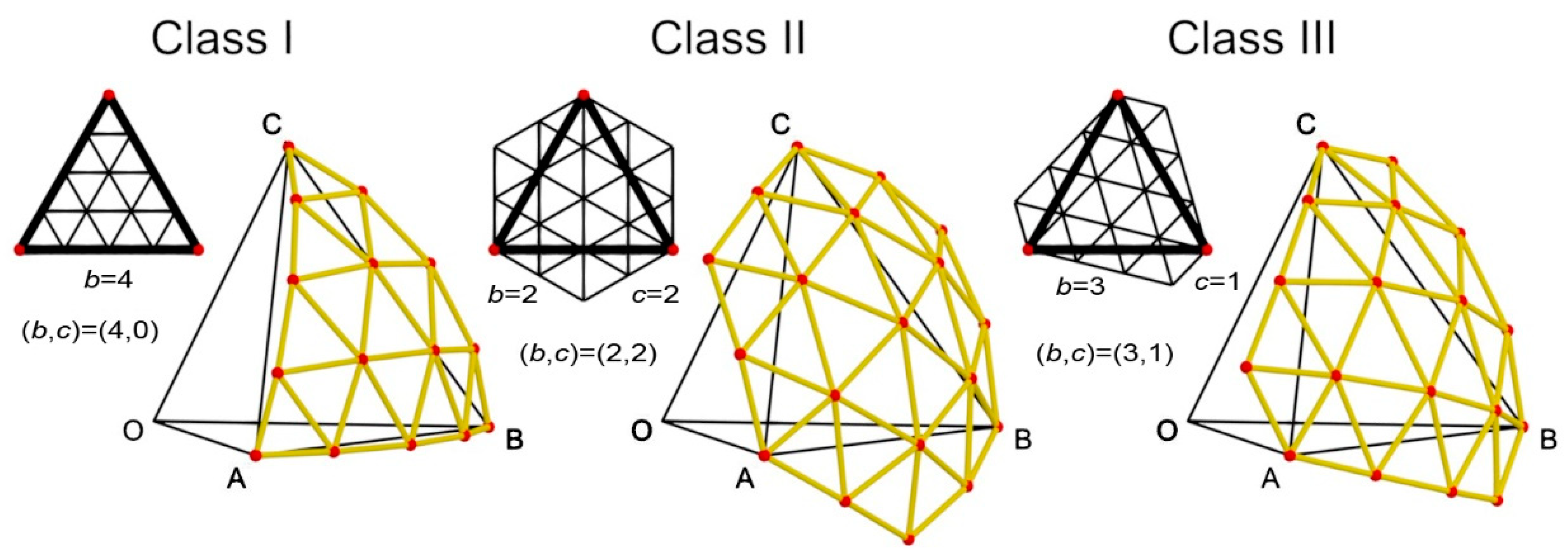
10], obtaining eight different methods that could be applied to two different topologies (Class I and Class II). During the next decade, H. M. Wenninger [
11] proposed a Class III inspired by the geometric characterization of virus capsules, which show certain skewed topologies (
Figure 2).
Yacoe and Davies proposed the geotangent structures in 1986 [
12]. These panel structures can have two types of faces, (i) regular polygons on the equator and on the north pole of the sphere, and (ii) at least half of the other faces being non-equilateral pentagons or hexagons. The sphere that is approximated by this kind of polyhedron is tangent to each edge in only one point, its section with the face’s plane being a circle inscribed in that face.
Because of the symmetry characteristics of the regular polyhedra used for this purpose, it is necessary to calculate just one single face (or a subdivision of the face, e.g., Schwartz triangle) in order to obtain the total definition of the global structure.
A specific application of this method is the design of driven geometry in architecture, using parametric modeling and genetic algorithms [
13].
2. Methodology
2.1. Geometry Concepts
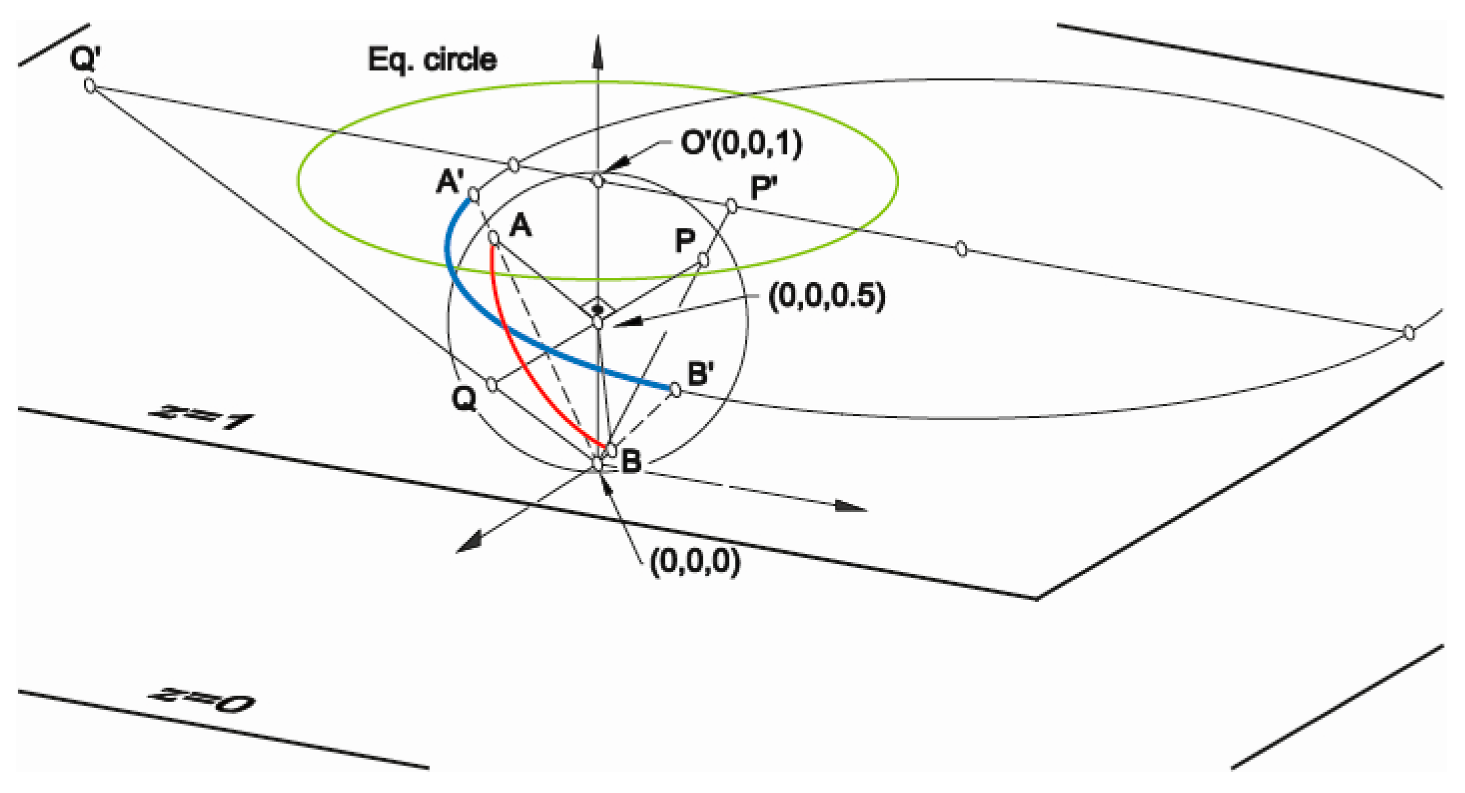
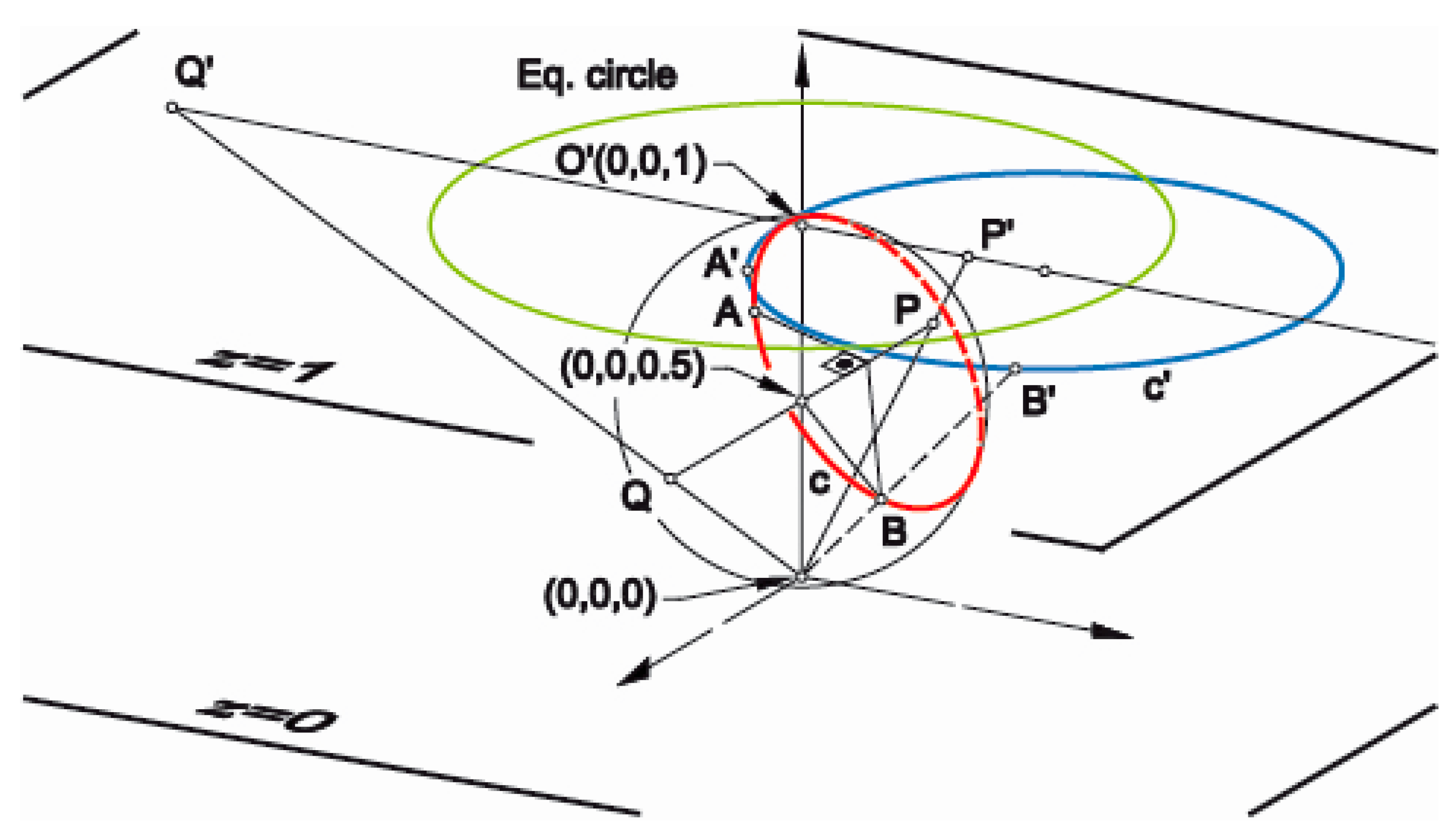
The Poincaré model is adopted to support the approach developed in this work, consisting of a plane model of elliptic geometry obtained by means of a stereographic projection of the points belonging to a sphere (Pi) onto a plane (P’i), and vice versa. The equation for the sphere is
x2 +
y2 + (
z − 0.5)
2 = (0.5)
2, and the equation for the plane is
z = 1 (upper tangent plane). The center of the stereographic projection is the origin of coordinates (this projection is an inversion using the unit sphere centered at the origin). In order to obtain a point-to-point correspondence between the sphere and the plane, the working Euclidean plane is extended, introducing a point at infinity (inversive plane) [
14].
As a reminder, in the bi-dimensional projection of the elliptic geometry, measurement of angles is conventional (the same as in Euclidean geometry), and lines (great circles of the sphere) are represented by circles intersecting the stereographic projection of the equatorial great circle in the antipodal (diametrically opposite) points. Henceforth, for the sake of brevity, these lines will be called as elliptic lines.
The procedure starts by selecting a set of points, S’, in the plane (called sites), from which the Delaunay triangulation (or Voronoi diagram) is calculated. The triangulation is stereographically projected onto the sphere, so that it creates an inscribed (or circumscribed) polyhedron that approximates this surface [
15].
The projection is strictly stereographic for triangulations, where each site, P’i, of the plane is transformed to a point, Pi, on the sphere. These points must be linked with respect to the connectivity of the original triangulation in
z = 1, giving birth to an inscribed polyhedron. However, this cannot be applied to the case of the Voronoi diagrams, where it is necessary to project the points of
z = 1 on the sphere and then calculate their respective polar planes. By changing the points for the planes, the duality of the problem in 3D space is established. A conventional projection from the origin of the coordinates of the vertices of each Voronoi cell onto their respective polar plane generates the vertices of the faces belonging to the circumscribed polyhedron (refer to the examples shown in the section about Study Cases). Taking into consideration the properties of Voronoi diagrams, the stereographic projection and polarity can be combined in a single expression that directly projects the vertices of the cells onto their final position in the space [
16].
The disposition of the sites chosen in
z = 1 corresponds to the stereographic projection of the vertices of the fundamental grid [
17] defined on the sphere (
Figure 3). Until this moment, it was not possible to define these sites directly on the plane. The method to obtain them will be shown in the following section.
2.2. Transformations Procedure
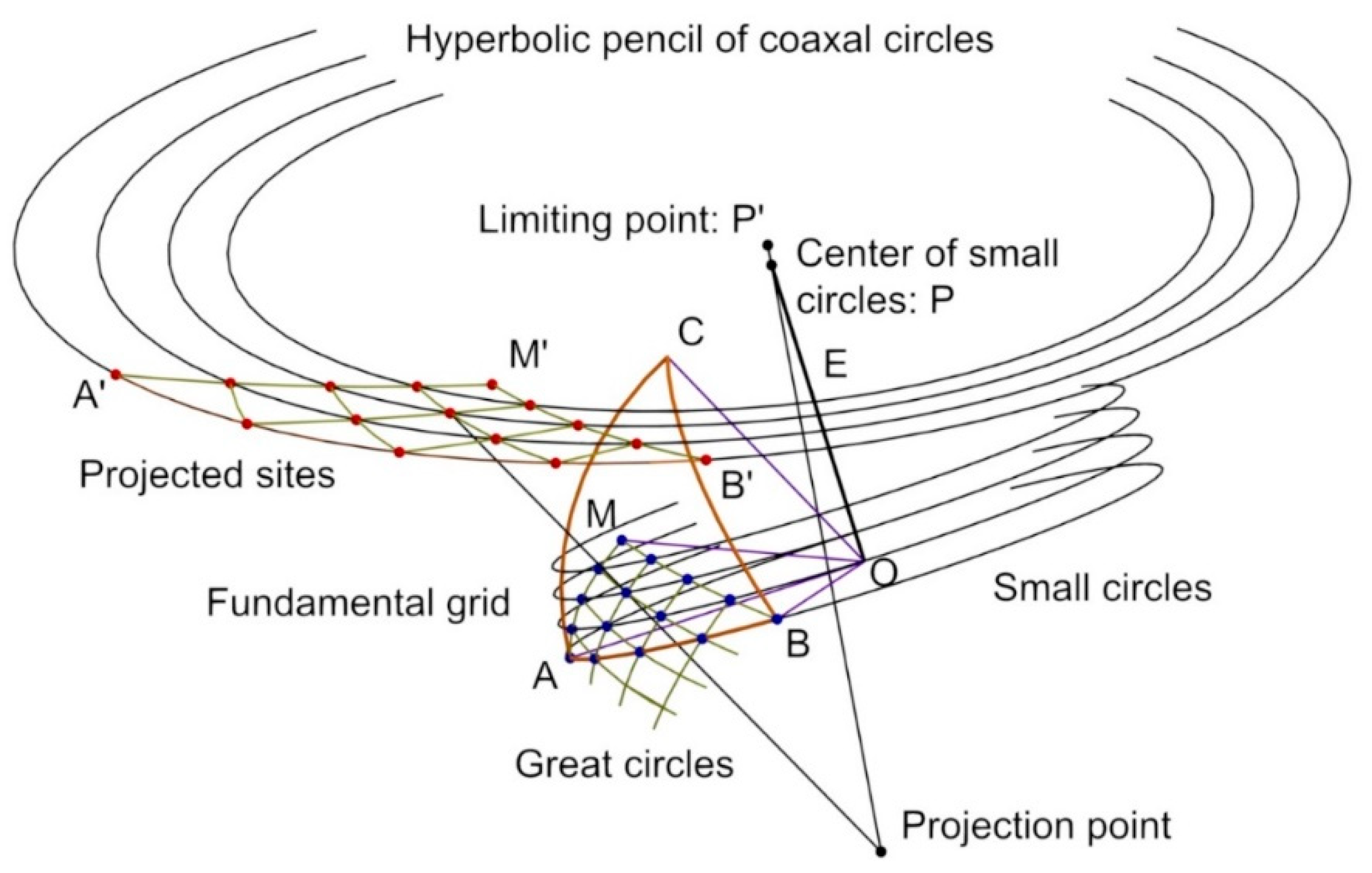
Let us consider the known the projections on the plane (A’, B’, C’) of the vertices (A, B, C) that define the spherical triangle (
Figure 4), as well as the projection of the equatorial great circle (intersection of the sphere with the plane
z = 0.5). In the stereographic projection, great circles and concentric small circles are transformed into elliptic lines and hyperbolic pencils of coaxal circles, respectively [
14].
This method makes use of the Möbius transformations (Equation (1)), consisting of rational linear functions of one complex variable
z, where
a,
b,
c, and
d are complex constants necessary for characterizing the transformation [
14]. These functions are both circular and conformal, so that they reproduce on the plane the transformations defined on the sphere (rotations, reflections, and spatial inversions), both direct (Equation (1), left) and opposite (Equation (1), right) [
18].
The correct definition of a Möbius transformation, by means of the complex constants
a,
b,
c, and
d of Equation (1), requires the identification of three points and their images, because either they preserve the cross ratio of four points, or they change it by their complex conjugation [
18]. The correspondence between the points and images depends on the transformation to be implemented, as will be explained in the next paragraphs.
Figure 5 shows the homologous transformation of a rotation on the sphere around the polar axis PQ. The endpoints of this axis (points P and Q) are projected onto the plane (P’ and Q’), which are transformed onto themselves after the rotation (P’
→P’; Q’
→Q’). Another third point (A’) as well as its transformed (B’), define the magnitude of the rotation to be performed (A’
→B’).
Similarly,
Figure 6 shows the homologous transformation of an inversion on the sphere, with respect to a reference circle c [
18] passing through points A and B. This curve is projected into c’ and those points into A’ and B’, which are self-inverse points (A’
→A’, B’
→B’). The constant of the inversion is established by setting the correspondence of any point with its transformed. With respect to any circle on the sphere, the polar points (P and Q) of the axis (PQ) perpendicular to the plane of such a circle are transformed into each other (P’
→Q’).
Particularly, an inversion on the sphere, with respect to a great circle, is equivalent to a mirror symmetry, with respect to the plane of the circle, therefore the reflection symmetry, with respect to an elliptic line, will be characterized in the same way as the inversion.
2.3. Fundamental Grid and Propagation of Sites
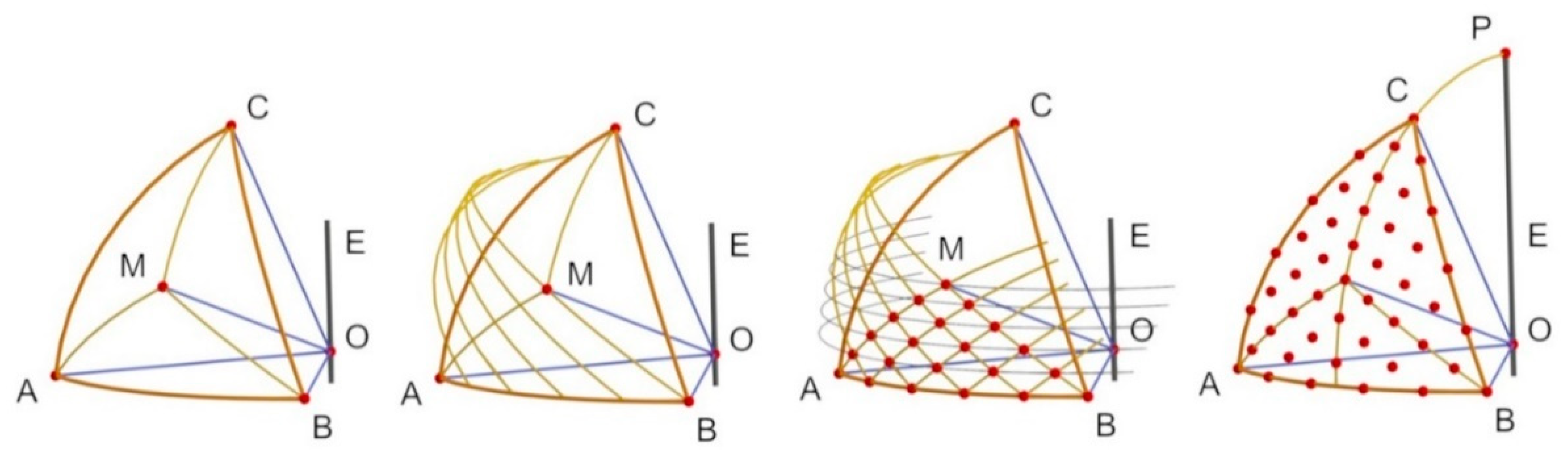
The following procedure will be used to propagate a fundamental grid in the projection of a regular spherical triangle (see
Figure 3 and
Figure 7). The starting point is the definition of the points A’, B’, C’, and O’ on the inversive plane by using stereographic projection, as well as the equatorial great circle.
- •
- 1.
Draw side A’B’ (there are two possible arches, keep the one at the opposite side point O’).
- 2.
Obtain projections P’ and Q’ from the endpoints of the polar axis perpendicular to the plane of the great circle containing A and B on the sphere. These points are the intersection of the lines perpendicular to the side A’B’ from A’ and B’.
- 3.
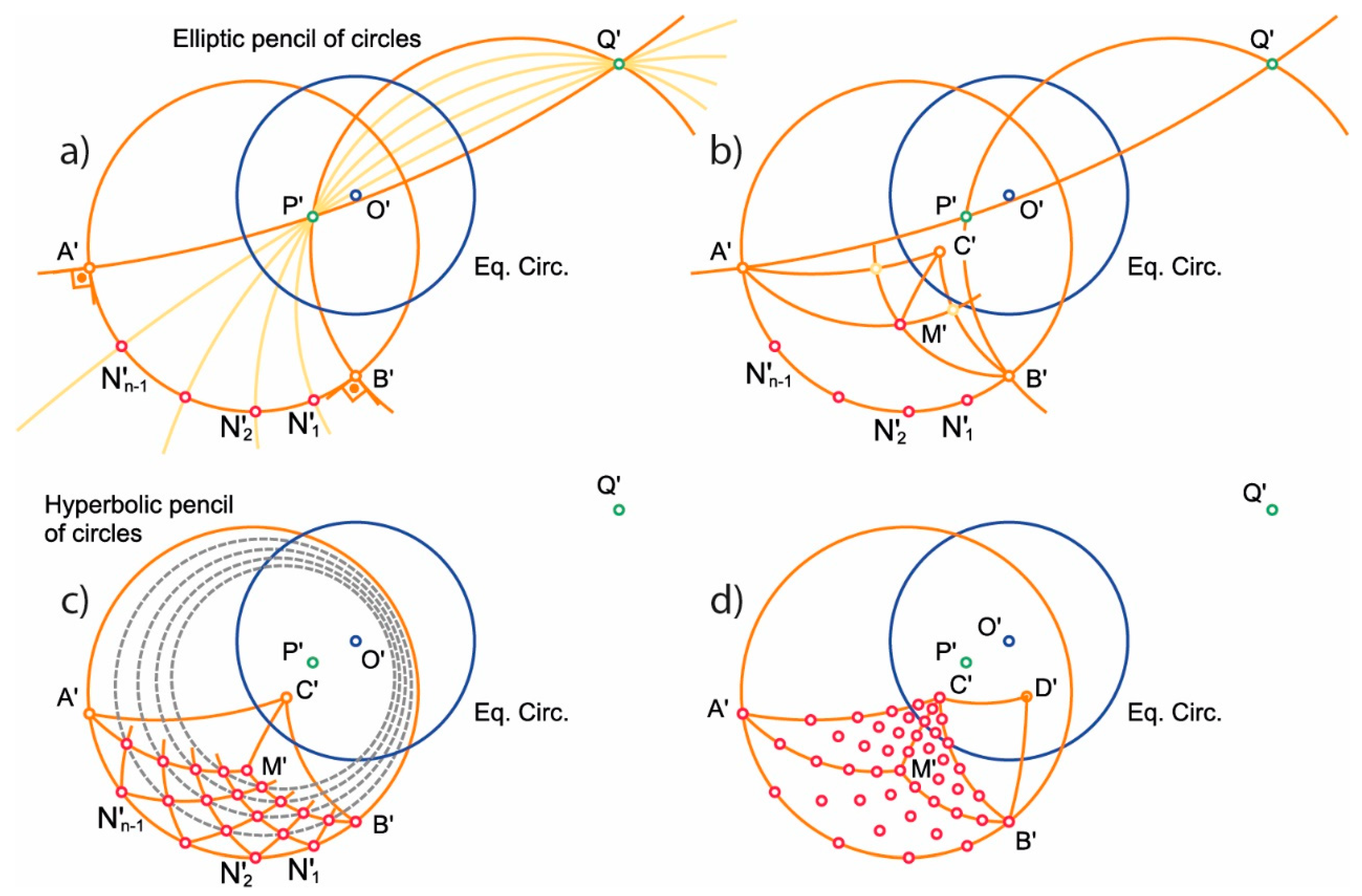
Divide side A’B’ into n equal parts (points N’i) by intersection with the elliptic lines dividing angle A’P’B’ into n equal parts (these lines belong to an elliptic pencil of circles through P’ and Q’).
- •
- 4.
Draw sides A’C’ and B’C’ and locate the middle point (M’) of the projected spherical triangle by intersection of the medians of both sides.
- •
- 5.
Define the Möbius transformation that performs the rotations of consecutive division points (N’i) of A’B’. Apply, in the triangle A’M’B’, such rotations to side B’M’ (direction B’
→A’) and to side A’M’ (direction A’
→B’). The intersections of the rotated sides define the points of the fundamental grid (which belong to a hyperbolic pencil of circles [
18]).
- •
- 6.
Propagate the fundamental grid to the whole projection of the spherical triangle by means of reflection symmetry, with respect to lines A’M’ and B’M’.
- 7.
Propagate the sites of the whole projection of the spherical triangle to the adjacent ones, by means of reflection symmetry, with respect to its three sides. Unknown vertices of the projections of the new spherical triangles are obtained by inversion (for example, vertex D’ is the inverse of A’, with respect of side B’C’).
2.4. Generalization of Models by Means of Power Diagrams
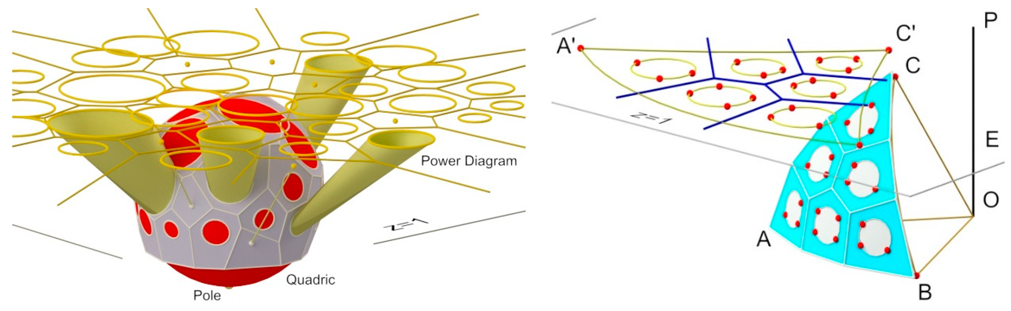
The design procedure outlined in the previous section allows to define both the inscribed and circumscribed polyhedra, depending on the actions applied to the points in plane z = 1. However, computational geometry has proved that it is possible to obtain solutions that are more generic when the following occurs:
In this case, each cell of the power diagram will lead to a face of the polyhedron approximating the quadric surface, which can cut, or not, such a surface (
Figure 8, right). If this happens, the section produced by the intersection is stereographically projected onto the plane as one of the circles of the power diagram.
For those situations that require more symmetrical configurations, it is possible to select the points from the fundamental grid, using this grid as a design template to define the generators (in this case, circles) of the power diagram (
Figure 8, right).
3. Study Cases
The procedure outlined in the previous section has been conceived for the definition of polyhedral structures approximating the sphere. Therefore, it is not restricted to the field of structural engineering, and it can also be applied to other fields such as those cited in
Section 1. Additionally, it has been stated that it is also possible to extend the catalogue of lattices in two directions.
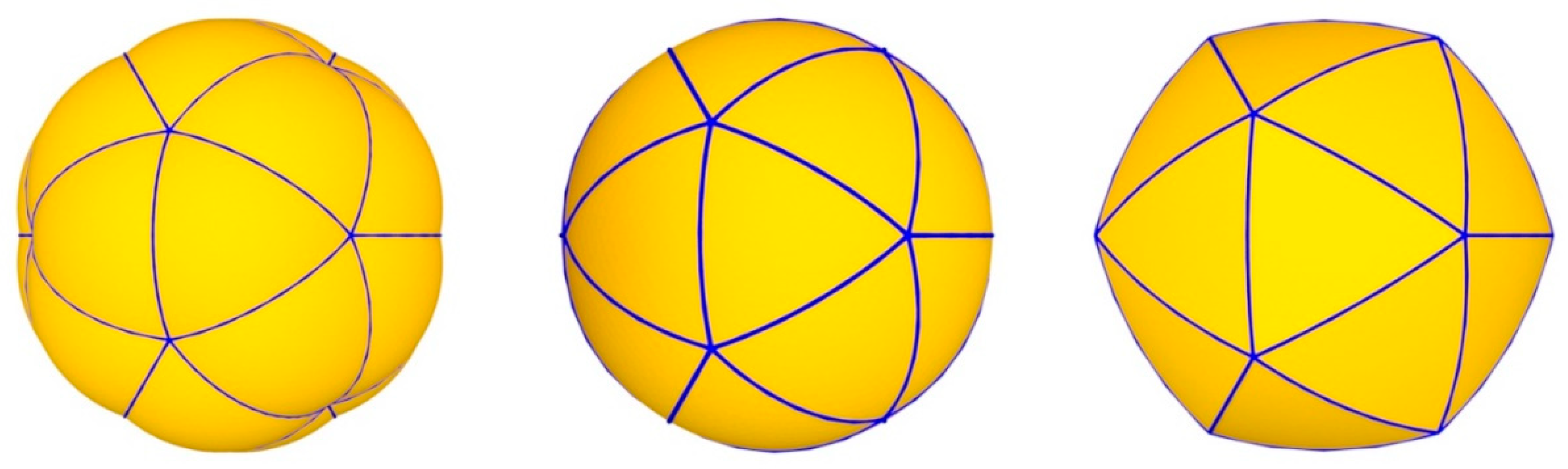
The first one is the use of cutting by parallel trihedra procedure [
17], which allows for generating two kinds of surfaces much more specialized, namely: the inflated and the flattened surfaces shown in
Figure 9 (left) and
Figure 9 (right), respectively.
The second one deals with the application of a projective transformation on any of the polyhedra associated to the sphere. This procedure allows for generating new meshes approximating other elliptic quadrics, both lattice and panel structures, which can present revolution symmetry (CR-tangent meshes [
15]) or not (C-tangent meshes [
19]), as can be shown in
Figure 10.
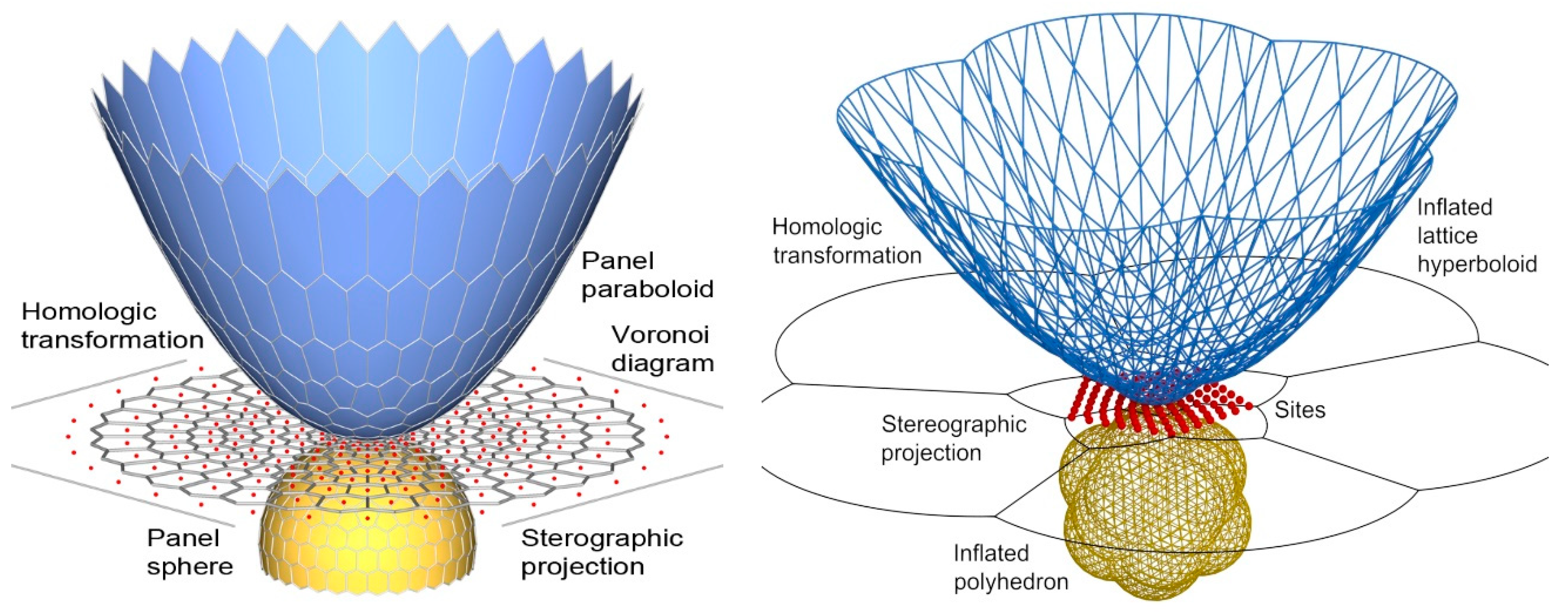
After obtaining the polyhedron approximating the sphere, it is possible to apply a specific homological transformation to the sphere (or to the obtained polyhedron) in such a way that the result is an elliptic quadric surface (or the approximating polyhedron).
Figure 10 (left) shows an application to a paraboloid of revolution, while
Figure 10 (right) depicts an application to a hyperboloid of revolution (globular).
4. Discussion
The proposed procedure assures the correct generation of meshes for any distribution of points in plane z = 1. Therefore, an adequate modification of the distribution of the sites would allow for emulating the solutions proposed by other researchers (Fuller, Clinton, Wester, etc.). Until now, the comparison of all of these models has been carried out using only graphical methods.
When the distribution of the sites matches the points of a fundamental grid, the result is an optimal mesh [
17], both for the lattice or the panel configurations (because of the duality between Delaunay triangulations and Voronoi diagrams).
The projective transformation generates polygons whose sizes are larger when they are farther from the origin of projection. Improved knowledge of the Möbius transformations is just one of the ways of ensuring that the edges of the polygons obtained in this way are more similar among them.
5. Conclusions
It is possible to design polyhedral structures approximating the sphere by means of procedures in the bi-dimensional plane. The application of Möbius transformations allows for replicating the operations (symmetry, rotation, and inversion) in the plane performed in the three-dimensional space. Therefore, an appropriate selection of sites can be made using computational geometry to generate (both lattice and panel) space structures with an optimal size and shape. As a result, computational geometry becomes a useful tool capable of providing new ideas for the development of design software and structure calculation, giving support to many different fields of science and technology.
By means of performing projective transformations, the polyhedra that approximate the sphere can become the polyhedra approximating any elliptic quadrics, although the optimal shape and size of the lattice or panels cannot be maintained. However, these kinds of transformations open a wide new catalogue of original spatial structures.
6. Further Research
Some interesting questions can still be asked from a structural point of view, namely: “Would it be possible to calculate the spatial mesh in the inversive plane?”, “How could we dimension geometrical and mechanical parameters to perform those calculations?”, and “How could we introduce the loads and boundary conditions to the so-defined structure?”.
From a different point of view, now taking into consideration the design and fabrication process, “Would it be possible to represent on the drawings the three-dimensional components (e.g. bars, nodes, and panels), usually represented symbolically (e.g. lines, points, and polygons) in a realistic manner?”.
Author Contributions
The authors contributed equally to this work, which comes integrally from J.A.D.-S.’s doctoral thesis, supervised by C.O. The methodology and supervision of article and thesis, C.O.; investigation and writing (original draft), J.A.D.-S.; software development for spatial space models and computational geometry, C.M.; writing, reviewing, and editing final manuscript, V.G.-J.
Funding
This research received no external funding.
Acknowledgments
Thanks to INGEGRAF for their contribution and financial support in the publishing process of this article.
Conflicts of Interest
The authors declare no conflict of interest.
References
- Aurenhammer, F. Power Diagrams: Properties, Algorithms and Applications. SIAM J. Comput. 1987, 16, 78–96. [Google Scholar] [CrossRef]
- Diaz, J.A.; Otero, C.; Togores, R.; Manchado, C. Power diagrams in the design of Chordal Space Structures. In Proceedings of the 2nd International Symposium on Voronoi Diagrams in Science and Engineering, Seoul, Korea, 10–13 October 2005; pp. 93–104. [Google Scholar]
- Wester, T. A Geodesic Dome-Type Based on Pure Plate Action. Int. J. Space Struct. 1990, 5, 155–167. [Google Scholar] [CrossRef]
- Fuller, R.B. Building Construction. U.S. Patent US2682235, 29 June 1954. [Google Scholar]
- Bauersfeld, W. Projection Planetarium and Shell Construction. Proc. Inst. Mech. Eng. 1957, 171, 75–80. [Google Scholar] [CrossRef]
- Fuller, R.B. Cartography. U.S. Patent US2393676, 29 January 1946. [Google Scholar]
- Snyder, J.P. An equal-area map projection for polyhedral globes. Cartographica 1992, 29, 10–21. [Google Scholar] [CrossRef]
- Coxeter, H.S.M. Virus macromolecules and geodesic domes. In A Spectrum of Mathematics; Butcher, J.C., Ed.; Auckland University Press: Auckland, New Zealand, 1972; pp. 98–108. [Google Scholar]
- Clinton, J.D. A topological model of the Buckminsterfullerene family of molecules and other clusters having icosahedral symmetry. Unpublished work. 1992. [Google Scholar]
- Clinton, J.D. Advanced Structural Geometry Studies. Part I: Polyhedral Subdivision Concepts for Structural Applications; NASA-CR-1734; NASA: Washington, DC, USA, 1971.
- Wenninger, M.J. Spherical Models; Cambridge University Press: Cambridge, UK, 1979. [Google Scholar]
- Yacoe, J.C. Polyhedral Structures that Approximate a Sphere. U.S. Patent US4679361, 14 July 1987. [Google Scholar]
- Turrin, M.; von Buelow, P.; Stouffs, R. Design explorations of performance driven geometry in architectural design using parametric modeling and genetic algorithms. Adv. Eng. Inform. 2011, 25, 656–675. [Google Scholar] [CrossRef]
- Coxeter, H.S.M. Introduction to Geometry; John Wiley and Sons: New York, NY, USA, 1969. [Google Scholar]
- Otero, C.; Gil, V.; Alvaro, J.I. CR-Tangent Meshes. IASS 2000, 41, 41–48. [Google Scholar]
- Rey Pastor, J.; Santaló, L.A.; Balazant, M. Geometría Analítica, 5th ed.; Kapelusz: Buenos Aires, Argentina, 1969; pp. 481–484. [Google Scholar]
- Alvaro, J.I.; Otero, C. Designing optimal spatial meshes: Cutting by parallel trihedra procedure. IASS 2000, 41, 101–110. [Google Scholar]
- Schwerdtfeger, H. Geometry of Complex Numbers. Circle Geometry, Moebius Transformation, Non-Euclidean Geometry; Dover Publications: New York, NY, USA, 1979. [Google Scholar]
- Otero, C.; Togores, R. Computational Geometry and Spatial Meshes. In Computational Science-ICCS 2002; Sloot, P.M.A., Hoekstra, A.G., Tan, C.J.K., Dongarra, J.J., Eds.; Springer: Heidelberg, Germany, 2002; pp. 315–324. [Google Scholar]
© 2018 by the authors. Licensee MDPI, Basel, Switzerland. This article is an open access article distributed under the terms and conditions of the Creative Commons Attribution (CC BY) license (http://creativecommons.org/licenses/by/4.0/).


