A Hierarchical Mapping System for Flat Identifier to Locator Resolution Based on Active Degree


1
School of Electronics and Communication Engineering, Zhengzhou University of Aeronautics, Zhengzhou 450046, China
2
Department of Technology, Zhengzhou University of Aeronautics, Zhengzhou 450046, China
*
Author to whom correspondence should be addressed.
Future Internet 2018, 10(8), 75; https://doi.org/10.3390/fi10080075
Submission received: 26 June 2018
/
Revised: 2 August 2018
/
Accepted: 7 August 2018
/
Published: 8 August 2018
Abstract
:Overloading of IP address semantics appeals for a new network architecture based on Identifier (ID)/Locator separation. The challenge of Identifier (ID)/Locator separation is how to solve the scalability and efficiency challenges of identity-to-location resolution. By analyzing the requirements of the Identifier (ID)/Locator separation protocol, this paper proposes a hierarchical mapping architecture on active-degree (HMAA). This HMAA was divided into three levels: active local level, neutral transfer level, and inert global level. Each mapping item is dynamically allocated to different levels to ensure minimizing delay according to its activity characteristics. The top layer CHORD is constructed by the Markov Decision Process, which can keep consistency between the physical topology and the logical topology. The simulation results on delay time show that HMAA can satisfy the scalability and efficiency requirements of an Identifier (ID)/Locator separation network.
1. Introduction
With the popularity of intelligent devices and diversified network services, the Internet has become one of the essential infrastructures of human society. However, it faces many challenges such as scalability, mobility, security, multi-homed, and many other challenges [1]. It is well known that the main cause of these challenges is IP semantic overload [2]. That is, an IP address represents both the ID (identifier) and Locator of an endpoint. Binding the ID of an endpoint with its locator results in conflicts with multi-homing, traffic engineering, mobility, and security. With newly emerging requirements in the industry, an architecture that follows the idea of ID/Locator separation is becoming more and more imperative [3].
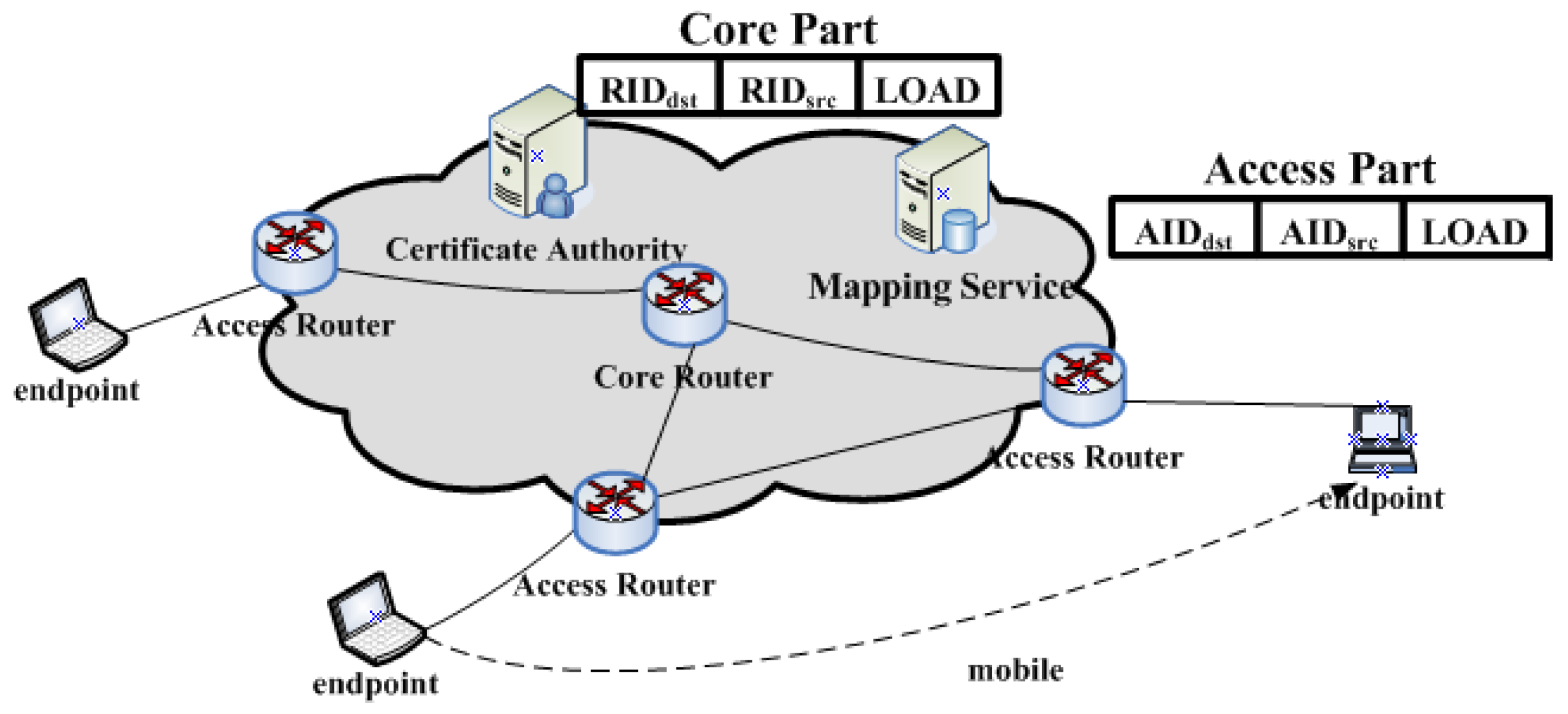
Several recent schemes are proposed with the aim to replace the single IP namespace of the Internet with two distinct namespaces (i.e., a locator namespace and an identifier namespace). These schemes are divided into two categories according to their relationship with the existing Internet. One is the evolution of the existing Internet, such as HIP(Host Identity Protocol) [4], LIN6 [5], and LISP (Locator/ID Separation Protocol) [6], while another is a completely new, revolutionary network architecture, such as universal network (UN) [7], as shown in Figure 1.
The UN consists of an access network (AN) and a core network (CN). Original IP addresses are changed to access identifiers (AIDs) for identifying endpoints and routing identifiers (RIDs) for locating endpoints in the Internet. Access identifiers must be replaced with RIDs when the packets enter a CN from an AN, and RIDs must be changed to AIDs when the packets leave from an CN. That is, a UN uses identifiers replacing the packet’s transmission, instead of encapsulating it.
Identifier replacing has some merits, as follows. Firstly, it supports mobility strongly like other ID/Locator separation schemes. Secondly, ANs do not know the locators and CNs dont know the IDs, which results in the attackers from ANs not being able to attack the endpoints of a CN. For example, a host attaching to its access router and which wants to attack by DDoS cannot control packets routed to the victim destination, and the attackers from the core part (sometimes an eavesdropper) cannot eavesdrop on the packet of a given user because they do not know the ID of the user. As a result, replacing addresses is more secure as compared to encapsulating packets.
The key challenge of ID/Locator separation is how to design a resolution system that can provide a corresponding RID to an AR (Access Router) for a given AID when the packets enter the CN, and provides a corresponding AID to an AR for a given RID when the packets leave the CN.
HIP [4] adds the host identity (HI) layer between transport layer and IP layer. The host identity tag (HIT) is used to identify the endpoint host, and IP is used only for routing in the network layer. HIP provides two main solutions for identifier resolving. The first solution uses dynamic DNS for resolving mapping. DNS always keeps the latest IP address and the corresponding HI/HIT for mobile endpoint host. There is no doubt that the host’s frequent mobility will cause a sharp performance decline of DNS servers, resulting in poor performance and scalability. Another limitation is that it cannot accurately resolve mapping information when the source and destination hosts move at the same time. The second solution uses a rendezvous server (RS) for resolving mapping. It requires that each home network must be configured by RS, which causes that the HIP is not incrementally deployed.
LIN6 [5] divides an IPv6 address into two parts: the identifier (i.e., LIN6 ID) and the exchange routing locator (i.e., LIN6 prefix). LIN6 ID is used in the upper layer for end-to-end communication, and the identifier-to-locator resolving is achieved by the protocol stack of the endpoint host and the mapping agency. However, LIN6 should be distinguished with MIPv6, which causes that the LIN6 namespace is limited too.
LISP [6] uses EID (Endpoint Identifier) representing the endpoint identifier, and RLOC (Routing Locator) representing the locators of routers and network interfaces. LISP-ALT, LISP-CONS, LISP-EMACS, LISP-NERD are the different resolving systems of LISP according to the differences of storing and querying mapping. Although different query and storage mechanisms are designed for resolving EID-to-RLOC, they all require the structure of EID to be aggregatable.
TLMS [8] proposes a two-level mapping model based on the PUSH/PULL mechanism, in which the actual mapping information is stored in bottom level and the upper level stores the reachability information of location of the actual mapping item locates. LMS [9] designs a hierarchical mapping system, but its identifier ELOC (identify endpoint) still uses a format similar to IP, which required ELOC is aggregative.
For a global locator or local locator, the aggregation requirement for EID or ELOC actually reflects the location information. In fact, for a network which uses the ID/Locator separation mechanism, the identifier should not contain any location information. That is, the identifier should be non-structural or flat. This makes it possible to find the storage position of an identifier-to-locator mapping only through two ways: flooding or storage based on specific rules advanced which the finder also knows. However, because the number of AIDs, the identifier in the UN, is huge, and one AID can map to any RID in theory, we must store mapping information based on specific rules advanced. In addition, mobility causes frequent mapping updates. Numerous mobile endpoints require controlling the cost and delay caused by the mapping item updates. Distinguishing the endpoints based on their mobile feature can improve the efficiency of mapping items resolving. Reference [10] proposed a mapping method based on energy level, but the construction method of the top layer is not deeply expressed, and its performance analysis is slightly insufficient.
This paper concentrated on the question of how to provide a locator resolution service for flat identifiers under the ID/Locator separation architecture using the replacement of addresses based on Reference [10]. The main goal is reducing the delay of mapping resolution from ID to locator.
We achieve the goal mainly by the following four methods: (1) Architecture: the mapping items storage architecture for resolving is divided into three different levels according to the different activity items stored. (2) Mapping items flow mechanism: based on the push mechanism, updated mapping items will be stored in the appropriate position; change the storage position dynamically according to the activity of an item; policy report (PR) is used for an identifier according to the different mobility of the corresponding endpoint. (3) Location awareness construction method of the top layer: using the Markov decision process to construct the top layer CHORD, thus keeping the consistency between the physical topology and the logical topology.
This paper is organized as follows. In Section 2 we present the overall framework of resolution. Section 3 focuses on the related process and mechanism of identification resolving. Section 4 focuses on the construction method of the top layer. Section 5 focuses on the performance analysis of the proposed method.
2. Hierarchical Mapping Architecture on Active-Degree (HMAA) for Identifier Resolution
Reference [11] points out that the activity of an IP subnet prefix meets the heavy-tailed distribution, in which the underlying reason is related to the psychological characteristics and social life habits of network users such as usage habits that do not change usually. So, by taking advantage of the character in the existing network, we “push” the active mapping items to network users under the ID/Locator separation architecture.
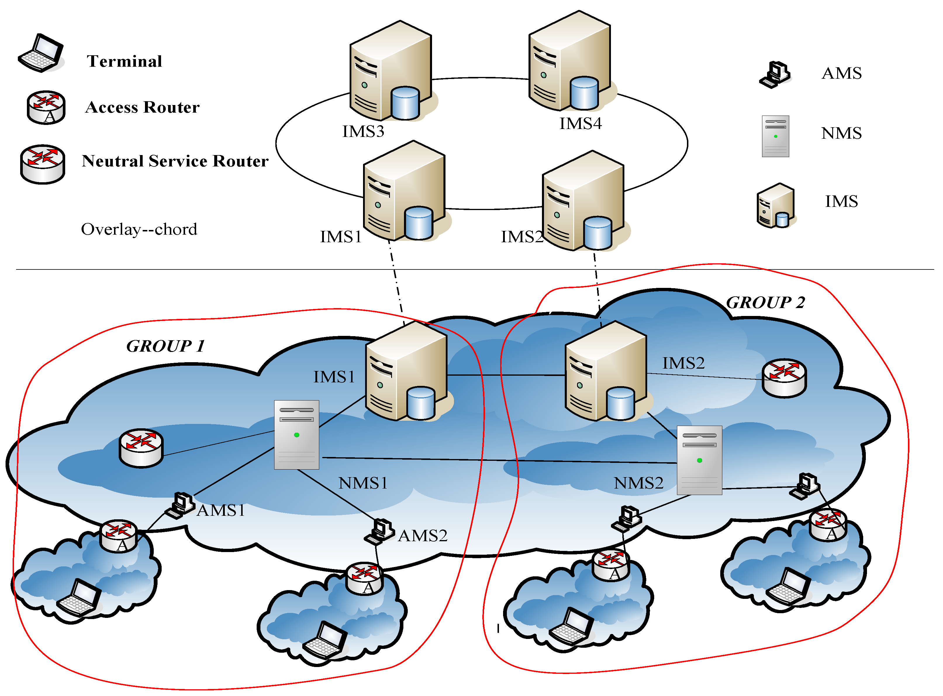
The mapping structure is divided into three levels: active local level, neutral transfer level, and inert global level. Their corresponding mapping servers are AMS (Active Mapping Server), NMS (Neutral Mapping Server), and IMS (Inert Mapping Server), respectively. Figure 2 shows the entire resolving system, which is called HMAA (Hierarchical Mapping Architecture on Active-Degree).
Here we use active-degree to indicate the activity of mapping items. The nearer to endpoint, the higher the active-degree. The mapping item which is used frequently will be assumed a higher active-degree to a special user and will be stored at the mapping server with the higher activity layer.
AMS provides services for one or a group of AR(s), stores related copies of frequently-used mapping items, and allocates appropriate RIDs to the corresponding endpoint AIDs if necessary. That is, it produces the original mapping item. The purpose of using AMS is to ensure the queries of mapping are quickly replied for most users communication; NMS stores less frequently used mapping items which are related to a group of ARs, and performs the Policy Report (PR) of mapping items, which aims to reduce the frequent mapping item updates caused by the numerous endpoint frequently move; IMS stores all the copies of mapping items, and every mapping item which is allocated by AMS should be reported to IMS. Storing all mapping items in IMS is to ensure the robustness of query for identifier-to-locator; mapping items are placed and dynamically flow between the three levels according to their activity.
Policy Report occurs in a special area we call GROUP. The so-called GROUP refers to a set consisting of several ARs, neutral services routers, AMSs and NMSs in the same geographical range. A neutral service router is a special core router, which directly associates with the corresponding NMS logically within the GROUP. A neutral service router deals with the first several packets sent to the mobile endpoints in the same GROUP, and informs the fact RIDs of mobile endpoints to communicate to peers. Within each GROUP there is one or more NMS, and each NMS is responsible for the storage of less frequently used communicating peers’ identifier mapping items corresponding of several AMSs in the GROUP and local endpoint mapping items reported by the ARs. In this paper, we consider the case that each GROUP has only one NMS, because we can regard each region as a group, which corresponds with an NMS and its several corresponding AMSs, as shown in Figure 2.
It should be noted that, in order to prevent the mapping system from possible user attacks, we deploy the mapping system in the routing identifier space, that is, every mapping server is identified by RID.
3. Mapping Items Flow Mechanism
3.1. Mapping Item in HMAA
In the abovementioned framework, HMAA, AMS is responsible for dynamically allocating an RID to each legal endpoint of local ARs, and storing the local mapping items of communicating peers used most commonly. So there are two tables in AMS: LRMT (Locate Register Mapping Table) and ARMT (Active Remote Mapping Table). The LRMT item at least is the three-tuple (AID, RID, T), where AID and RID is a mapping correspondence (hereinafter similarly), and T is the established time of the mapping item. The ARMT item at least is the three-tuple (AID, RID, F), where F is the activity of the mapping item.
There are two tables in NMS: NLMT (Neutral Locate Mapping Table) and NRMT (Neutral Remote Mapping Table). The NLMT stores the mapping item generated by the endpoint registration in the GROUP. The NLMT item at least is the six-tuple (AID, RID, RIDa, T, M, Flag), where RIDa is the corresponding mobile routing identifier (mRID). The mRID is different from a general routing identifier (RID) in that a mobile routing identifier indicates its corresponding endpoint as a mobile endpoint. A mobile routing identifier is not assigned by default, but is assigned only if the endpoint is frequently mobile. T is the establishing time of the mapping item, and M is a measure of the change rate of the mapping item with an initial value of 0. Flag is used for PR, which indicates that the routing identifier NMS reports to IMS is RID or RIDa. We set Flag = true if the reported routing identifier is RID, otherwise false. The NRMT stores less frequently used communication peers’ mapping item called by local endpoints, which at least is the four-tuple (AID, RID, F, RIDm), where F is the activity of the mapping item.
The format of the mapping item in IMS is at least the three-tuple (AID, RID, (RIDm)). The number of elements in set (RIDm) is limited, recording all cache location of the mapping item. As the aggregation of RID is available, we can easily merge these elements when the number of elements exceeds a const. Because the number of mapping items stored in IMS is large, we use DHT. Here we use the CHORD.
In this framework, we need to be concerned with the following points: (1) mapping item initialization and update; (2) mapping item query; and (3) the mechanism by which mapping item flow in HMAA.
3.2. Definition of Active Degree
There is an element of “F” in the mapping item of both ARMT and NRMT, which marks the activity level. In fact, “F” is very important in HMAA and is the soul of the whole structure. It decides how the mapping item flows in the three different levels.
Active degree (AD) refers to the activity level of the mapping item in the mapping resolution system; that is the times the mapping item is queried over a period of time.
That is
Here, QN represents the number of queries for a mapping item in time ST.
3.3. Mapping Item Initialization, Update, and PR Mechanism
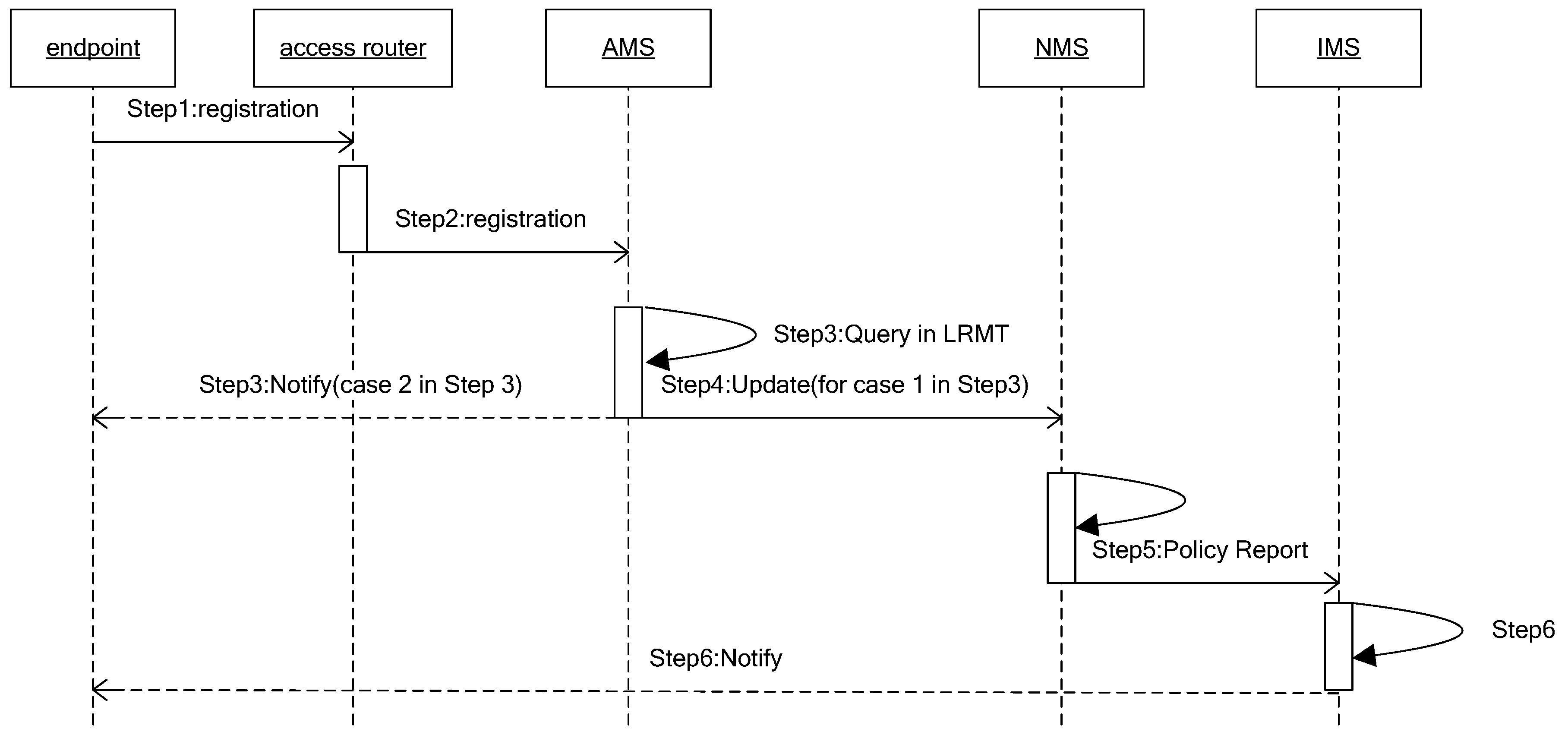
When an endpoint registers to an access router or moves to an area a new access router covers, it will be allocated a corresponding routing identifier (RID). The difference is that moving to a new access router will cause an update of the relevant copies, and the main process is described in Figure 3. The process includes six steps:
- Step 1
- Endpoint with AIDi sends registration request packet to the access router;
- Step 2
- Access router verifies the legitimacy of the endpoint. If legitimate, sends registration request packet to the corresponding AMS. Otherwise, refuses service;
- Step 3
- AMS queries the AIDi item in LRMT.
- Case 1
- If no relevant mapping item, allocates a new routing locator RIDai for it, and turns to Step 4.
- Case 2
- Otherwise, using the original mapping item, sends a registration success message to AIDi and exits.
- Step 4
- The new mapping item of AIDi (AIDi:RIDai,) is stored in AMS and reported to the corresponding NMS;
- Step 5
- NMS queries the mapping item in NLMT using key AIDi. The process is divided into the following cases:
- Case 1
- If there is not a relevant mapping item, then it generates an item (AIDi, RIDai, RIDa, T, M, Flag) and stores it in NLMT, and reports (AIDi, RIDai) to IMS.
- Case 2
- If there is a relevant mapping item (AIDi, RID, RIDa, T, M, Flag) related to AIDi, it judges if the (AIDi, RID) is valid through sending the verification message to RID.
If valid, indicating that now the endpoint has two routing locators, that is, it is a multi-homing endpoint, then it adds a piece of mapping information for this item. If the Flag shows that the mapping item reported to IMS is an access routing identifier, then it needs to report this mapping item to IMS. Invalid item conditions will be described in the PR mechanism next.
We can set the reported mapping item as (AIDi:RIDi).
- Step 6
- Receiving the mapping table, IMS queries the mapping item with key AIDi based on the relevant CHORD algorithms. If successful, assuming the mapping item is (AIDi, RID0, (RIDm)), it firstly verifies the legitimacy of this mapping items. If legal, then it adds the item (AIDi, RIDi, (RIDm)), and notifies this item to (RIDm). Otherwise, it stores it directly.
In the second case of Step 5, that is, if invalid, it indicates that the endpoint has moved. Then, it replaces RID with RIDai. To distinguish frequently mobile hosts and fixed hosts, apparently, the M in item is the key. In fact, for the mobile endpoint, its mobility is a long-time statistical result. Therefore, we use the number of that endpoint’s leaps across two different access routers as the statistical value of M. Then we judge an endpoint as a mobile terminal or fixed terminal in the following way. Supposing the current clock is Tn, if ( is a const), it is a fixed endpoint, and reports its access routing identifier. Otherwise, it is a frequently mobile endpoint, and assigns a mobile routing identifier and reports to IMS. We call this method the Policy Report (PR) mechanism mentioned above.
3.4. Mapping Item Query and Lifting Mechanism
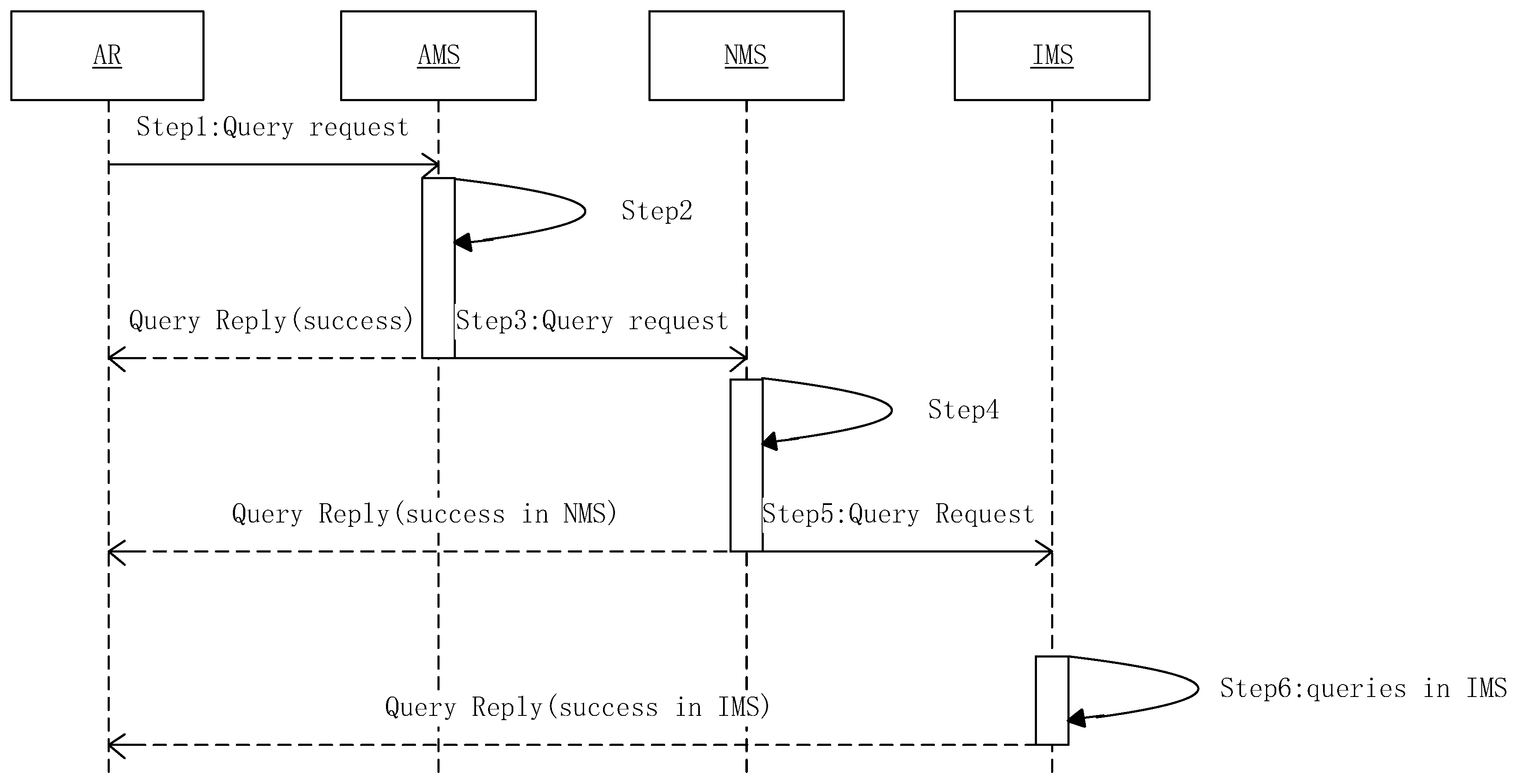
When the endpoint A (AIDa) launches a communication to endpoint B (AIDb), the access router of A needs query mapping information about B. Meanwhile, in order to avoid the access router of B querying the mapping information of A, A sends its own mapping information to B in the first communication. The main process of query mapping information is shown in Figure 4. The process includes six steps:
- Step 1
- The access router sends a request to AMS for querying the relevant mapping items of AIDb;
- Step 2
- It queries the relevant mapping items using the key AIDb in ARMT of AMS. If successful, the value of F in the mapping items should be updated according to Formula (1), and returns the result;
- Step 3
- AMS sends a query request to the corresponding NMS;
- Step 4
- It queries the mapping of AIDb in NRMT, if successful, the value of F in the mapping items should be updated according to Formula (1), and it starts the mapping item lifting mechanism mentions next in this Section, and returns the result;
- Step 5
- NMS sends a query request to IMS;
- Step 6
- It queries the mapping of AIDb in IMS, and adds the corresponding item in relevant NRMT, and returns the result; otherwise, the query fails (the intended user does not exist).
It should be noted that once a unit of time ΔT has passed, items in AMS and NMS should update their activity according to Formula (1). This allows the previously often used mapping item exit the current level when it is now no longer often used, as to avoid data contamination.
The above-mentioned mapping items lifting mechanism decides how the mapping items flow up and down in HMAA according to their usage. It relates to these two levels: active local level and neutral transfer level. There are two different situations: (1) mapping items move from inert global level to neutral transfer level; and (2) the activity of mapping items is high enough and triggers the move from the neutral transfer level to active local level.
We assume the minimum activity value of mapping items in an NMS at the neutral transfer level is Fnmin, and the maximum value is Fnmax. The minimum activity value of mapping items in an NMS at the active local level is Famin, and the maximum value is Famax. The above values are local property, that is, they are only valid for one mapping server.
For case (1), in order to ensure the mapping items at the neutral transfer level are not deleted too quickly, set the element F of mapping items as Fnmax/2.
For case (2), assuming the number of AMS, which one NMS serves, is n. To map an item in NRMT, if (), then put the mapping item into the corresponding AMS and set the activity value as Famax/2; move the mapping item with the smallest activity value from AMS to NRMT, and set the activity value as Fnmax/2.
The mapping item mentioned above moves from the low level to the high level. Conversely, if a mapping item (AID, RID, F) has a low query activity and other items need to enter the server, the AMS reports the mapping item to the corresponding NMS, and the NMS directly deletes the mapping item. Of course, it needs to report the address changes of the cache to the IMS.
3.5. Multi-Homing Supporting with Multi-Mapping Item Mechanism
When an endpoint gets services by accessing two or more access routers at the same time, it creates problems for mapping item management where the different AMSs assigns different RIDs, and each RID is effective. As we consider the case that AMS supports only services for one access router, there are not two valid RIDs corresponding to an AID in the AMS. Therefore, we only consider the NLMT and IMS. We focus on verifying mapping item validity and adding it to the mapping table.
Suppose the AMS/NMS storing a routing identifier RIDm reports a mapping item (AID, RID0). After the query in the NLMT/IMT, the corresponding item is (AID, RID, RIDa/(RIDm)). The multi-mapping item mechanism consists of two steps. In order to describe them clearly, we divided them into two cases:
- Case 1
- AMS reports to NMS, and the corresponding item queried in NLMT is (AID, RID, RIDa).
- Step 1
- Checks RIDm (corresponding to an AMS) whether the RID is under its management. If so, it indicates the queried item in NLMT is invalid, replaces the RID with RID0 in (AID, RID, RIDa), sends a mapping update message to IMS, and exits;
- Step 2
- Sends RID a message and checks if the RID of the corresponding AID in (AID, RID) is valid. If valid, showing that it is a multi-homing endpoint, it forms a new item (AID, RID0,), stores it locally, and reports this item to IMS; if invalid, it deletes the item.
- Case 2
- NMS reports to IMS, and the corresponding item queried in IMT is (AID, RID, RIDm).
- Step 1
- Checks RIDm (corresponding to an NMS) and whether its an RID under its management. If so, showing that it is a multi-homing endpoint, forms a new item (AID, RID0, {RIDm}...), stores it locally, and sends a mapping update message to (RIDm), and then exits;
- Step 2
- Sends RID a message, and checks if the RID of the corresponding AID in (AID, RID, RIDm1, RIDm2) is valid, If valid, showing that it is a multi-homing endpoint, forms a new item (AID, RID0, {RIDm}...), stores it locally, and sends a mapping update message to {RIDm}; if invalid, indicating the original item has expired, and it is not a multi-homing endpoint, it deletes the item.
The above mechanism can be used to ensure that there are many mapping items for one endpoint at the same time, instead of the latter item replacing previous items, which supports multi-homing.
4. Construction Method of the Top Layer Consisting of IMS
The top layer consisting of IMS is organized by CHORD. In the original CHORD, the physical node is organized into a loop, and each node identification is assigned by hashing the node address. In the system designed in this paper, the construction of the loop should consider the proximity of the nodes in the physical network as far as possible, and keep the consistency between the physical topology and the logical topology. When building a loop, it starts from an initial node and builds along the sequence of adjacent nodes, similar to a sequential decision process, and is only related to the current node, independent of the selected nodes in the loop, that is, it is memoryless. Therefore, in this section, the mapping resolution system building process is modeled as a Markov Decision Process (MDP) [12].
4.1. Model Building
The solution to a decision problem is to calculate a strategy that maximizes the user’s set of optimal criteria, which is called the optimal strategy. The optimization criterion of the Markov Decision Process used in this section is the total expectation reward under bounded conditions. In order to build a position aware DHT, this section uses the MDP model to describe the construction process of the mapping resolution system, and obtains an optimal construction strategy by solving the Markov Decision problem.
4.1.1. Decision Point, State, Action, and Transfer Probability
The system construction process can be naturally divided into some decision points, and each decision point corresponds to a node selection in the construction process. Obviously, the number of mapping resolution servers in the system is limited, so the construction process belongs to a bounded problem. In the process of system construction, the system state is defined as all the nodes that may be selected, and represents the node identification, is used to represent the current state of the node , and represents the number of nodes. Then, the state space can be represented as . At each decision point, the decision is made based on the current state according to the transfer probability and the action is selected from the action space. To avoid routing loops, each node can only choose one time, That is, the action space can be expressed as a set of remaining candidate nodes, . After executing the action, the system will be transferred from the current state to the state . Considering the characteristics of the construction process, the transfer probability can be defined as.
where and represent the maximum and minimum hops from the current node to the candidate node respectively, represents the hops between the currently selected node and the selected node .
4.1.2. Reward Function
When the reward function is designed, the physical distance and the logical delay between the current node and the selected next node should be taken into consideration, and an optimal or approximately optimal mapping resolution system is constructed from the whole. The reward function can be defined as the combination of the physical distance and the logical delay between the current node and the next node, considering the possibility that the time delay between the nodes adjacent to the physical location is not necessarily the shortest. The represents the gain from the physical distance between the nodes, and the represents the gain from the logical delay, where represents the states and represents the action. The total reward function can be defined as
where , > 0, is a weight factor. The weight factor provides an extra feature for the system and can change the proportion between two revenue functions by adjusting the weight factor, and the different weight factor values can be applied to different scenarios.
In reward function, hop count is used as a measure of distance, and represents the maximum distance between the current node and all selectable next nodes. So the distance reward function can be defined as
From Formula (4), we can see that the closer the selected node is from the current node, the greater the system gains.
The time delay reward function can be defined as:
where represents the time delay between the current node and all possible selected nodes, and the represents the delay between the current node and the next node to be selected. From Formula (5), we can see that the smaller the delay between the selected node and the current node, the greater the system gains.
4.1.3. Optimization Equation
The goal of the decision problem is to calculate a strategy that maximizes the standard value of a certain optimization. The Markov Decision Process optimization standard used in the system construction process is the total expected reward value with a limited boundary. In the process of constructing the system, the total expected reward value is the sum of the gains from physical distance and logical delay. Given a strategy and an initial state , the MDP optimization problem can be formulated as
where represents the optimal strategy. According to the characteristics of MDP, the optimized value function is unique and can be defined as the solution of Formula (7).
Formula (7) indicates that the total reward value of a certain state is the sum of the expected immediate reward and the discount reward that is expected to be obtained from the best action. Given the optimal value function, the optimal strategy can be expressed as
In the process of building the system, the MDP optimal policy represents which node to choose as the next node’s decision. According to the optimal strategy, we can construct a mapping analysis system which is optimal or suboptimal in the overall delay performance.
4.2. Construction Algorithm
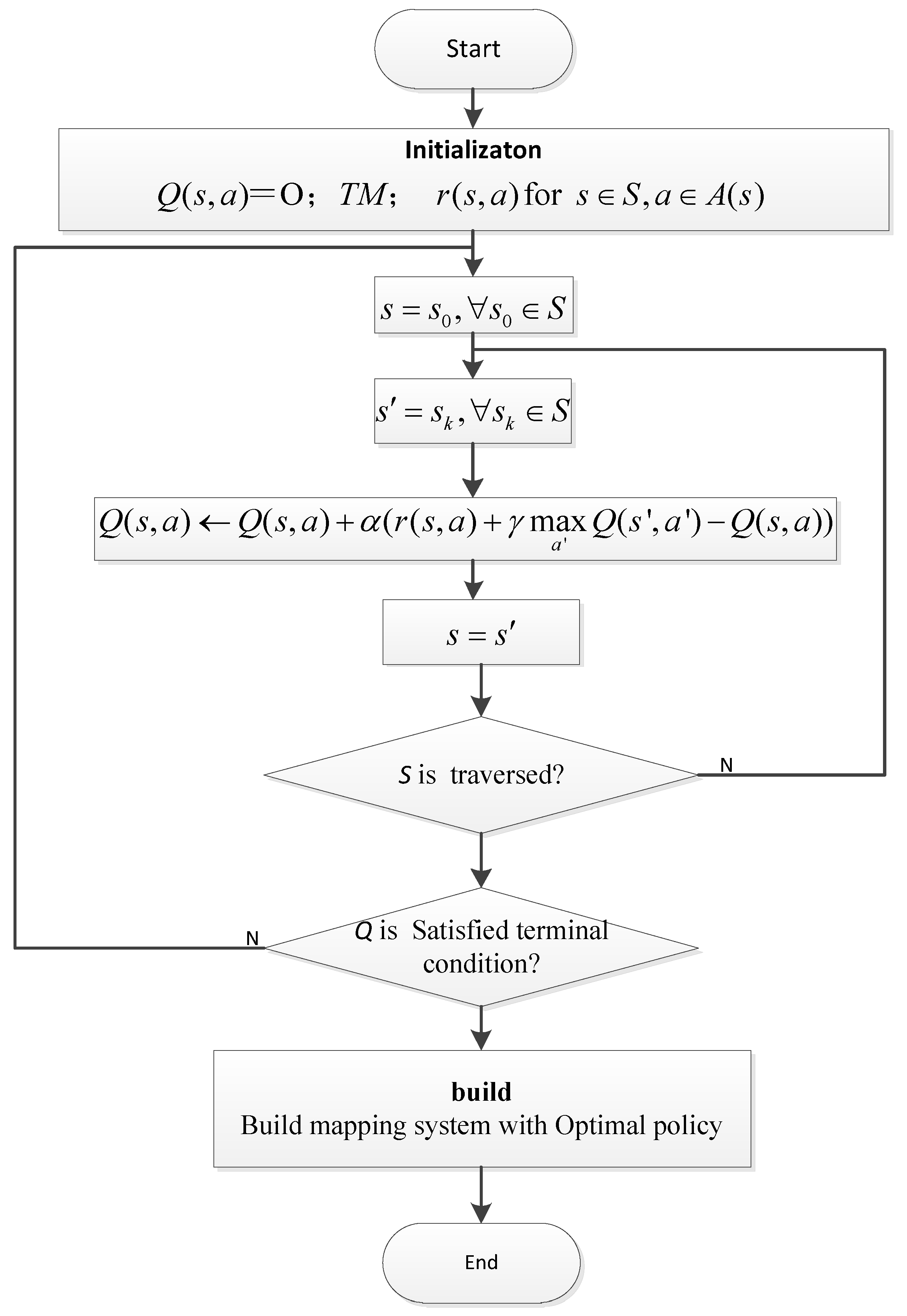
Q-learning [13] is usually used to solve MDP problems with unknown prior parameters. Q learning uses the Q function to simulate the cumulative reward. The Q function represents the maximum reward that can be obtained by executing action in state . In the process of learning, we first start with an initial state of , and then update recursively according to Formula (9) in the form of continuous trial and error.
The recursive definition of the Q function is the root of Q learning. Taking into account the characteristics of the construction process, based on the improvement of Q learning, the Markov Decision Making algorithm MDC (Markov Decision Construction) is proposed which is shown in Figure 5. The algorithm contains the following three steps:
- Step 1
- Initialization: The MDC algorithm first initializes the Q matrix to be zero and uses the topological matrix TM and the reward function matrix as input, and initializes all the parameters.
- Step 2
- Iteration: When the algorithm satisfies the termination condition, the iteration process is terminated. If the termination condition is not satisfied, the iteration process continues and calculates a complete construction path containing all nodes from the given initial node s0. In the process of building path computation, the system starts from the initial state s0 and executes a series of actions according to the greedy strategy. After executing each action, the system updates according to Formula (9). In addition, the influence of the loop must be removed in the process of constructing the path.
- Step 3
- Build: After the iteration is terminated, the optimal construction strategy will be found from the Q matrix. Then, based on the optimal construction strategy, we can build a mapping resolution system with optimal delay performance.
4.3. Analysis of Algorithm Complexity
From the flow of the above algorithm, it can be seen that:
In step 1, it is necessary to initialize the Q matrix required O(Ns,a) times, which O(Ns,a) is the number of state values.
In step 2, it is necessary to calculate a complete construction path that contains all nodes of the given initial node s0, and all possible states needed to be iterated in the worst case. This can be solved in O(Ns,a) times too.
The entire computing process needs to be circulated O(M) times, with M representing the number of Q-learning algorithms exploring the scene. Therefore, the complexity of the MDC algorithm is O(MNs,a). A detailed analysis of algorithm complexity is shown in Reference [14].
5. Performance Analysis and Simulation
5.1. Experimental Parameters
This section builds a simulation environment based on the overlay network simulation framework OverSim [15]. OverSim is a P2P overlay network simulation module running on OMNeT++ [16]. OMNeT++ is a discrete event driven simulator, which is widely used in the academic field. In order to simulate the application scene, the network topology is randomly created according to the typical Internet model InetUnderlay, and the network topology is composed of 10 backbone routers and 100 access routers. The number of mapping resolution servers is set in two cases. One is that the number of mapped parsing servers is less than 1000. In this case, the number of mapping resolution servers increases from 100 to 1000 with an interval of 100, which is mainly used to evaluate the performance of the mapping resolution system under the small regular mode network. Another case is that the number of mapping resolution servers is increasing from 1000 to 10,000 with an interval of 1000, which is mainly used to assess the performance of the mapping resolution system in a large network environment. Each access router has 100 terminals on average, so there are approximately 10,000 terminal nodes in the network. In every experiment, the number of mapping resolution servers is constant. This is because the mapping resolution system proposed in this paper is mainly used in an Internet backbone network. In a backbone network, the probability of node joining/leaving or failure in the mapping analysis system is very small. Therefore, the effect of node disturbance (churn) can be ignored in the evaluation process of the performance of the mapping resolution system.
In each experiment, each mapping resolution server is registered with an average of 1000 mapping items, so when the number of mapping resolution servers is 1000, the overall mapping resolution system has approximately 1,000,000 mapping items on the whole in the process of experimental measurement, each terminal node runs a test program periodically sending mapping resolution requests with a request interval of 1 s. The request pattern follows the web page browsing model proposed in Reference [17]. The popularity of mapping resolution parses items follows a Zipf probability distribution similar to the popularity of web pages, uniformly distributed 160 bit length identifiers are used to map the parsing system. The activity threshold is set to (ADmin + ADmax)/2, with ADmin and ADmax representing the minimum and maximum values of the mapping information activity in the local active mapping server, respectively. To reflect the general situation, the experiment was repeated 10 times and the average value of 10 times was taken as the final result. Furthermore, the time of each simulation was set to 1 h.
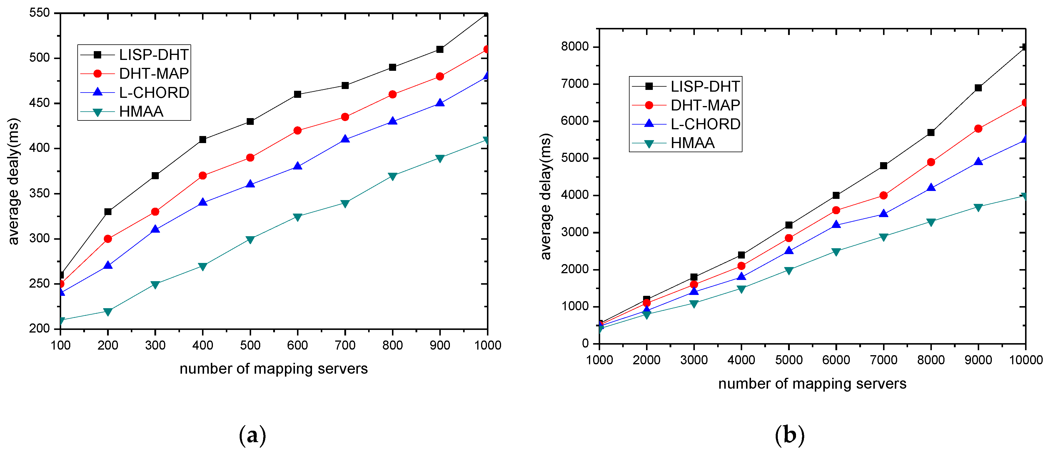
5.2. Average Delay of Mapping
The average delay of mapping is very important to the mapping resolution system, because it defines the time required between sending a mapping parse request and receiving the mapping item later. An important goal of the mapping resolution service design is to keep mapping delay at an acceptable level even though the number of tags is very large.
In Figure 6, the x-axis represents the size of the mapping resolution system, and the y-axis represents the average mapping delay. Figure 6a gives a comparison of the simulation results of average mapping delay in small networks. It can be seen from the figure that the mapping system proposed in this paper has a lower average mapping resolution delay than LISP-DHT [18], DHT-MAP [2], and Lchord [19]. The average decreased by 18%, 13%, and 8%, respectively. This proves that when the network size is small, the mapping system proposed in this paper is effective in reducing the mapping resolution delay. Figure 6b gives the average mapping delay comparison of different mapping systems under large-scale network conditions. It can be seen from the figure that the mapping system proposed in this paper has a lower average mapping resolution delay than LISP-DHT, DHT-MAP, and Lchord. The average decreased by 32%, 23%, and 13%, respectively. Especially, with the increasing scale of the mapping system, the advantage of the mapping system proposed in this paper is more obvious. This shows that when the network size is large, the mapping system proposed in this paper is more effective in reducing the mapping resolution delay.
5.3. Average Delay of One-Hop
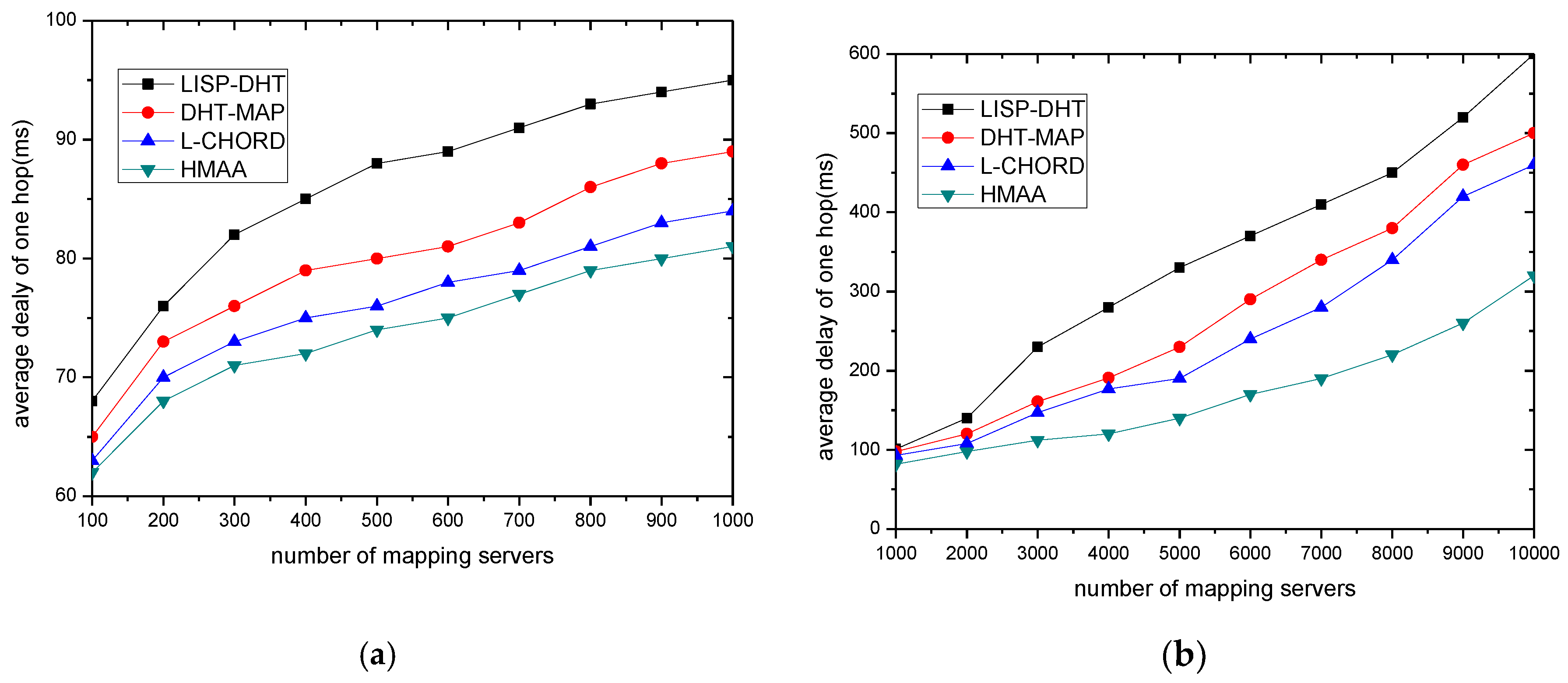
This section evaluates the average delay of one-hop. Average delay of one-hop is the ratio of average delay of mapping to hop count. It can accurately reflect physical network structure and delay characteristics. To some extent, it can also reflect the matching degree between physical topology and logical topology.
Figure 7 gives the comparison of the average hop delay performance of several mapping resolution systems under different network sizes. Figure 7a gives a comparison of the average delay of one-hop under a small-scale network. It can be seen from the figure that the performance of the proposed system and Lchord is better than that of LISP-DHT and DHT-MAP, which is because the proposed system and Lchord are mapping systems based on location aware DHT. Figure 7b gives a comparison of the average delay of one-hop under a large-scale network. It can be seen from the figure that the performance gap between the proposed system and the Lchord increases with the scale of the number of increasing of mapping servers, which shows that the advantage of the proposed mapping system in a large-scale network is more obvious. This result can be explained by two points. For the first point, the structure of HMAA is in accordance with the current Internet. This can guarantee that the mapping requests are met in the shortest path. For the second point, the difference between HMAA and Lchord is that the construction of the overlay in HMAA not only depends on the physical topology, but also depends on the logical topology. This can avoid bottleneck nodes which may lead to high one-hop delay efficiently.
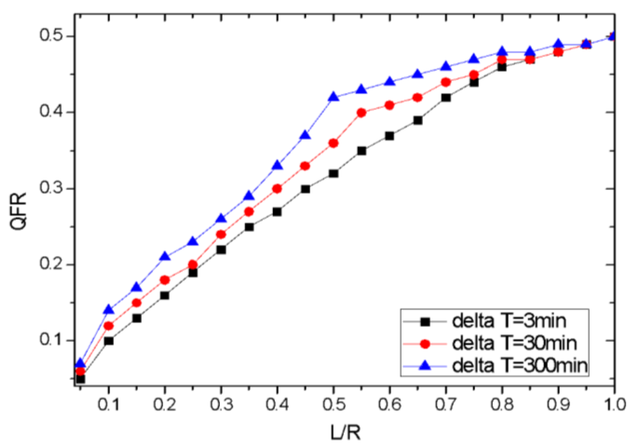
5.4. Query Failure Rate (QFR)
Since hosts roam from one access router to another access router, their ID-to-locator mapping items change accordingly by reporting to the IMS. If the cache timeout for a mapping item is too short, an AMS frequently queries the mapping system (IMS), but the new item perhaps does not update. This results in the failure of the query.
In fact, the query failure rate is impacted by factors including the capacity of the mapping server cache, ∆T, the definition and update of F, and other factors. We only simulated the capacity of mapping server cache and ∆T in this paper because they are the main factors.
The simulation was completed based on the structure shown in Figure 2. We used PC simulation of the three entities: IMS, NMS, and AMS. The data collected over 30 days can be accessed from UCB1993 [9]. The data can be ordered as destination IP address: communication time. We assume one time of communication corresponding stands for one time of mapping query, the destination IP address stands for AID, and assume that the mapping entries have been stored in the existing IMS. In the simulation, we defined F as the number of queries that F adding 1 with a query occurs, and decrease 1 with the time ∆T past, which replaces the defined for the activity in Formula (1) with the simplified method.
We reproduced the communicating process, and the statistic of QFR in AMS for query is shown in Figure 8. Here L/R stands for the rate of AMS local cache size to remote AID numbers.
Figure 8 shows the QFR increased with the cache size. When the L/R increased to a certain amount, the QFR no longer increased rapidly. We can also conclude that the QFR was correlative to ∆T. This result can be explained by two points. First, the larger the AMS cache size, the less the query from IMS was, which resulted in more failure. In addition, the larger the ∆T, the less the query from IMS was, which resulted in more failure too.
6. Conclusions
This paper presents an identifier resolving architecture called HMAA under the ID/Locator separation mechanism. The identifier mapping information (mapping item) is stored at different levels according to their degree of activity, and dynamically flows up and down through different levels. According to different mobility characteristics of an endpoint, a different policy report is executed to reduce the cost of mapping item updating. The top layer CHORD is constructed by the Markov Decision Process, which can keep the consistency between the physical topology and the logical topology. The simulation results show that HMAA can satisfy the scalability and efficiency requirements of the Identifier (ID)/Locator separation network. Of course, the simulation of QFR is relatively simple. Next, we will further study the impact of relevant factors on QFR.
Author Contributions
Conceptualization: J.L. and S.H.; Data curation: S.H.; Methodology: J.L. and Y.W.; Writing—original draft: J.L.
Funding
This work was supported in part by the National Natural Science Foundation of China (Grant No. 61672471), the key scientific research project of colleges and universities in Henan province plan (Grant No. 19A630033, Grant No. 19A510025 and Grant No. 19A510024), by the China Postdoctoral Science Foundation (Grant No. 2018M633733), and the Scientific and Technological Key Project of Henan Province (Grant No. 182102210449).
Acknowledgments
The authors acknowledge all the support from the above programs. They would also like to thank the anonymous reviewers and the associate editor for their useful comments.
Conflicts of Interest
The authors declare no conflict of interest.
References
- Ramirez, W.; Masip-Bruin, X.; Yannuzzi, M.; Serral-Gracia, R.; Martinez, A.; Siddiqui, M.S. A survey and taxonomy of ID/Locator Split Architectures. Comput. Netw. 2014, 60, 13–33. [Google Scholar] [CrossRef]
- Zhang, H.; Luo, H.; Chao, H.C. Dealing with Mobility-Caused Outdated Mappings in Networks with Identifier/Locator Separation. IEEE Trans. Emerg. Top. Comput. 2016, 4, 199–213. [Google Scholar] [CrossRef]
- Conti, M.; Chong, S.; Fdida, S.; Jiad, W.; Karle, H.; Linf, Yi.; Mähöneng, P.; Maierh, M.; Molvai, R.; Uhlig, S.; et al. Research challenges towards the Future Internet. Comput. Commun. 2011, 34, 2115–2134. [Google Scholar] [CrossRef]
- Nikander, P.; Ylitalo, J.; Wall, J. Integrating Security, Mobility and Multi-Homing in a HIP Way. In Proceedings of the 10th Network and Distributed System Security Symposium, NDSS 2003, San Diego, CA, USA, 6–7 February 2003. [Google Scholar]
- Teraoka, F. LIN6: A Solution to Mobility and Multi-Homing in IPv6; Internet Draft Ietf; University of Tokyo: Tokyo, Japan, 2003. [Google Scholar]
- Gohar, M.; Bashir, F.; Choi, J.G.; Koh, S.; Ahmad, W. A hash-based distributed mapping control scheme in mobile locator-identifier separation protocol networks. Int. J. Netw. Manag. 2017, 27, e1961. [Google Scholar] [CrossRef]
- Luo, H.; Zhang, H.; Zukerman, M. Decoupling the design of identifier-to-locator mapping services from identifiers. Comput. Netw. 2011, 55, 959–974. [Google Scholar] [CrossRef]
- Wu, W.C.; Chen, Y.M. TLMS: A Novel DRM Scheme for Multimedia Sharing in P2P Networks. In Proceedings of the IEEE 2009 Fifth International Conference on Intelligent Information Hiding and Multimedia Signal Processing, Kyoto, Japan, 12–14 September 2009; pp. 873–876. [Google Scholar] [CrossRef]
- Sun, L.; Yin, X.; Wang, Z.; Wu, J. LMS: A Layered Mapping System for Scalable Routing. In Proceedings of the 13th IEEE Global Internet Symposium, San Diego, CA, USA, 19 March 2010. [Google Scholar]
- Liu, J.; Wu, J.; Cheng, D.; Liang, W.; Lan, J. An Energy-Level Topology Architecture for Flat Identifier Resolution. Adv. Sci. Lett. 2012, 5, 766–770. [Google Scholar] [CrossRef]
- Lin, S.C.; Wang, P.; Akyildiz, I.F.; Luo, M. Delay-Based Maximum Power-Weight Scheduling with Heavy-Tailed Traffic. IEEE/ACM Trans. Netw. 2017, 25, 2540–2555. [Google Scholar] [CrossRef]
- Anselmi, J.; Dufour, F.; Prieto-Rumeau, T. Computable approximations for continuous-time Markov decision processes on Borel spaces based on empirical measures. J. Math. Anal. Appl. 2016, 443, 1323–1361. [Google Scholar] [CrossRef]
- Morozs, N.; Clarke, T.; Grace, D.; Zhao, Q. Distributed Q-learning based dynamic spectrum management in cognitive cellular systems: Choosing the right learning rate. In Proceedings of the 2014 IEEE Symposium on Computers and Communications (ISCC), Funchal, Portugal, 23–26 June 2014. [Google Scholar]
- Watkins, C.J.C.H. Learning from Delayed Rewards. Robot. Auton. Syst. 1989, 15, 233–235. [Google Scholar] [CrossRef]
- OverSim. The Overlay Simulation Framework. Available online: http://www.oversim.org/ (accessed on 30 April 2018).
- Steinbach, T.; Meyer, P.; Buschmann, S. Extending OMNeT++ Towards a Platform for the Design of Future In-Vehicle Network Architectures. In Proceedings of the OMNeT++ Community Summit, Brno University of Technology, Czech Republic, 15–16 September 2016. [Google Scholar]
- Johnson, T.; Seeling, P. Landing on the mobile web: From browsing to long term modeling. IEEE Commun. Mag. 2016, 54, 146–151. [Google Scholar] [CrossRef]
- Mathy, L.; Iannone, L. LISP-DHT: Towards a DHT to map identifiers onto locators. In Proceedings of the ACM CONEXT Conference, New York, NY, USA, 10–13 December 2008; pp. 1–6. [Google Scholar] [CrossRef]
- Zhao, G.; Cui, R.; Liu, Y. Lchord: Locality-aware chord for fast mapping in ID/Locator split routing. J. Comput. Inf. Syst. 2013, 9, 1399–1406. [Google Scholar]
Figure 1.
Universal Network (UN): A kind of ID/Locator separation network.

Figure 2.
Hierarchical mapping architecture on active-degree (HMAA).

Figure 3.
Mapping item initialization, update, and policy report (PR).

Figure 4.
Mapping item query.

Figure 5.
Markov Decision Construction (MDC) procedure.

Figure 6.
Average mapping delay comparisons: (a) Average mapping delay in small-scale networks; and (b) average mapping delay in large-scale networks.
Figure 6.
Average mapping delay comparisons: (a) Average mapping delay in small-scale networks; and (b) average mapping delay in large-scale networks.

Figure 7.
Average delay of one-hop: (a) small scale networks; and (b) large-scale networks.

Figure 8.
Query failure rate (QFR) compared to the rate of AMS local cache size to remote AID numbers (L/R).
Figure 8.
Query failure rate (QFR) compared to the rate of AMS local cache size to remote AID numbers (L/R).

© 2018 by the authors. Licensee MDPI, Basel, Switzerland. This article is an open access article distributed under the terms and conditions of the Creative Commons Attribution (CC BY) license (http://creativecommons.org/licenses/by/4.0/).
Share and Cite
MDPI and ACS Style
Liu, J.; Huo, S.; Wang, Y. A Hierarchical Mapping System for Flat Identifier to Locator Resolution Based on Active Degree. Future Internet 2018, 10, 75. https://doi.org/10.3390/fi10080075
AMA Style
Liu J, Huo S, Wang Y. A Hierarchical Mapping System for Flat Identifier to Locator Resolution Based on Active Degree. Future Internet. 2018; 10(8):75. https://doi.org/10.3390/fi10080075
Chicago/Turabian StyleLiu, Jianqiang, Shuai Huo, and Yi Wang. 2018. "A Hierarchical Mapping System for Flat Identifier to Locator Resolution Based on Active Degree" Future Internet 10, no. 8: 75. https://doi.org/10.3390/fi10080075
Note that from the first issue of 2016, this journal uses article numbers instead of page numbers. See further details here.