A Review on Recent Advances and Future Trends of Transformerless Inverter Structures for Single-Phase Grid-Connected Photovoltaic Systems

 ,
, 
 ,
,  ,
,
Abstract
:1. Introduction
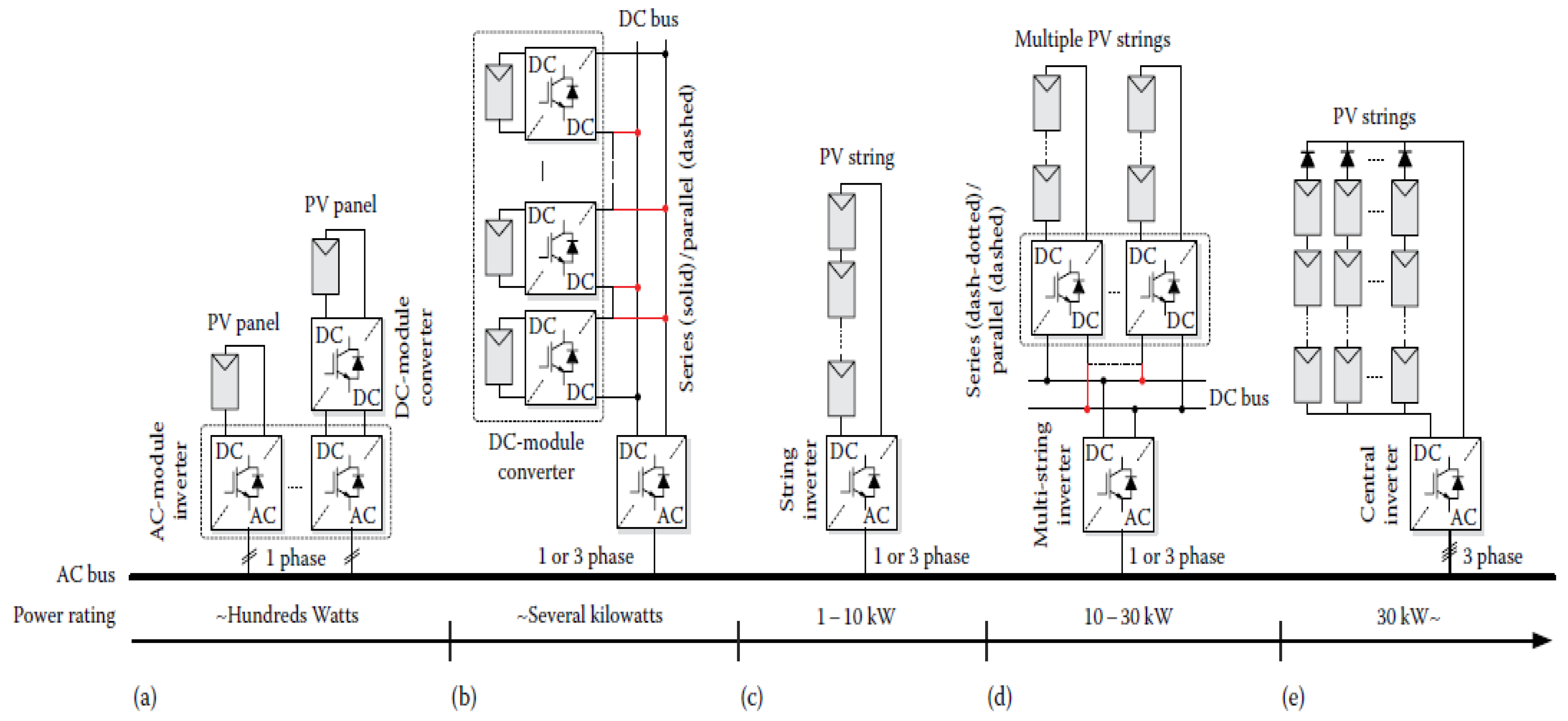
2. Power Converter Technology for PV Systems
- (a)
- H-bridge or full-bridge (BP)
- (b)
- NPC
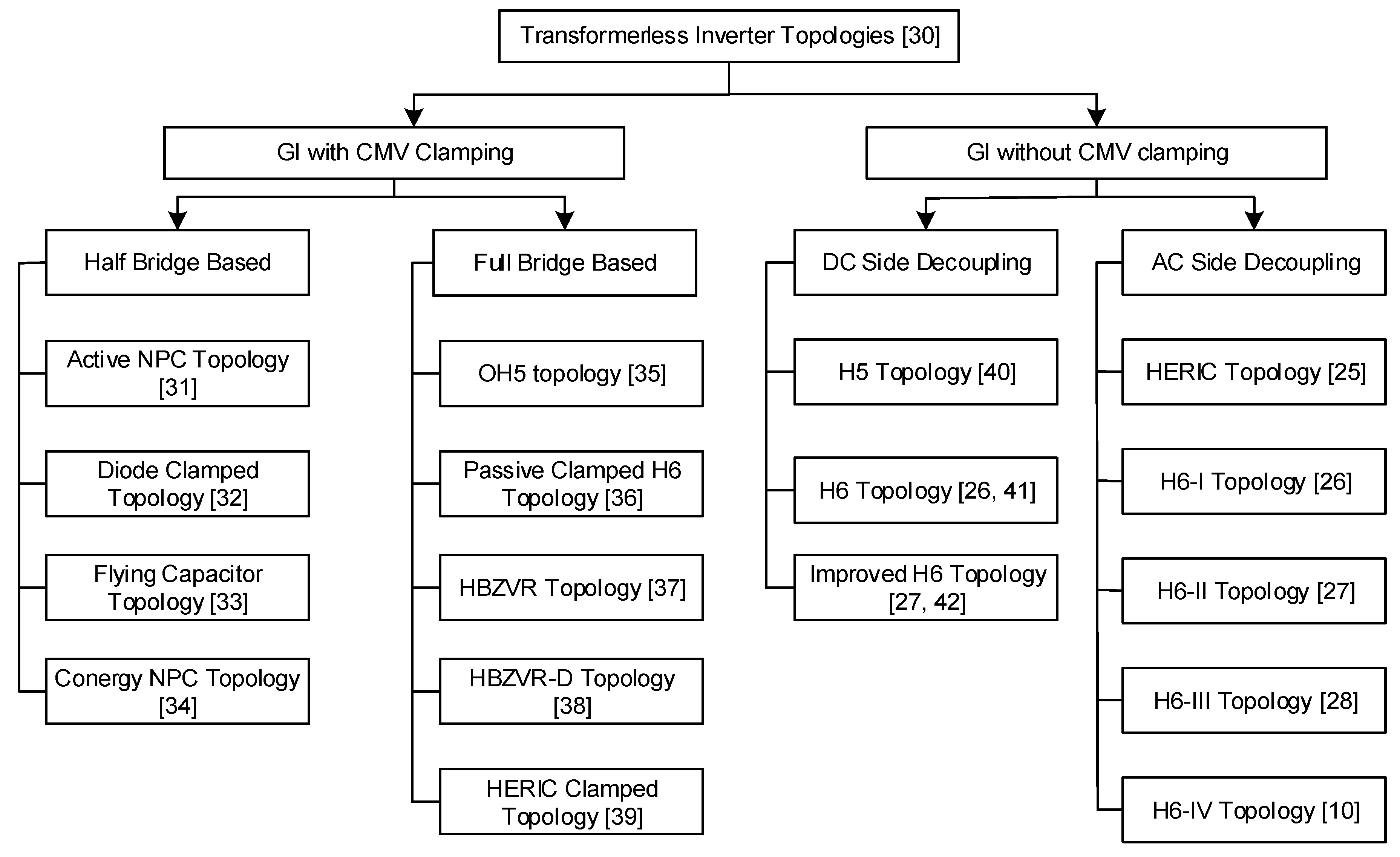
Classification of Transformerless Inverter Topologies
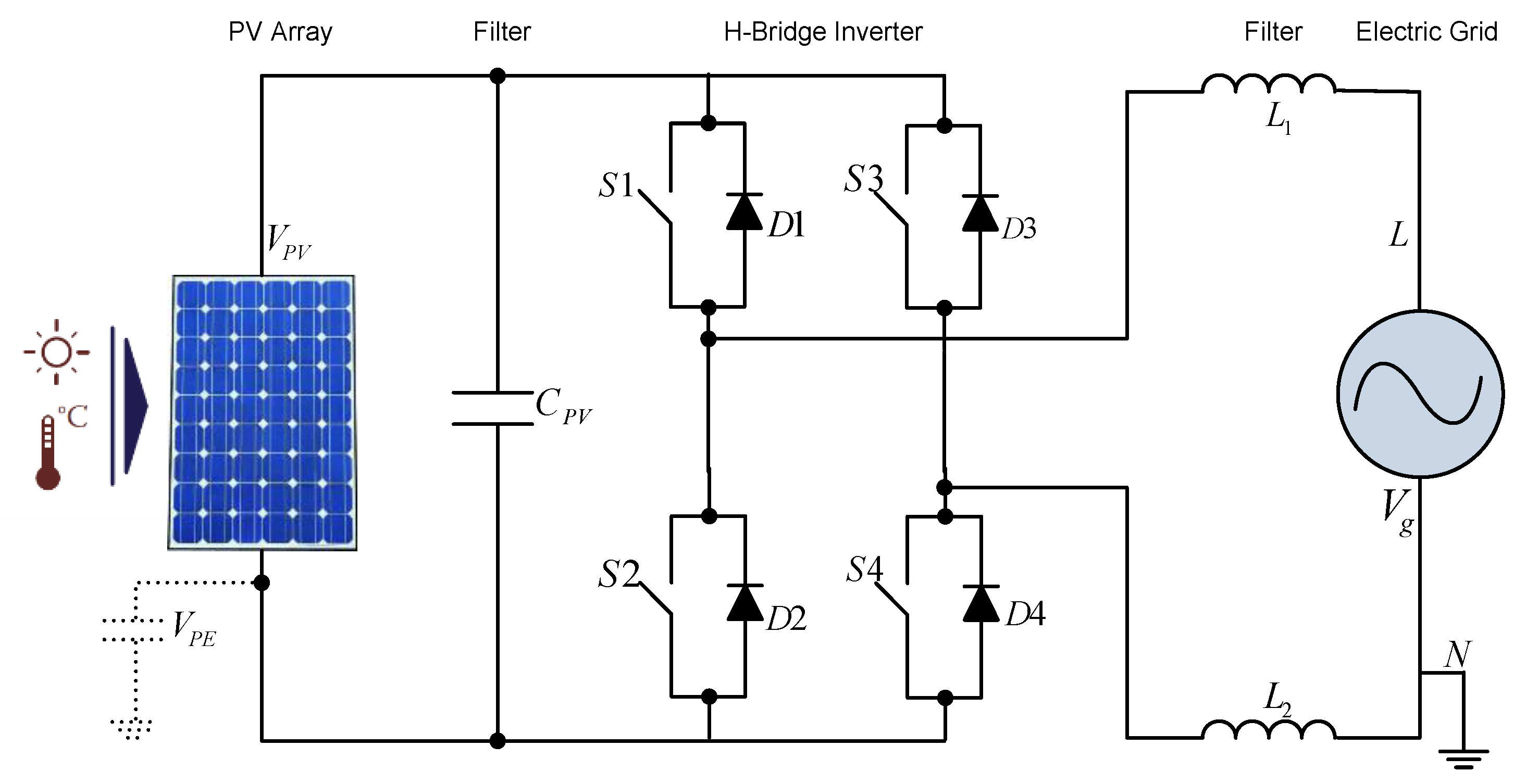
3. H-bridge Based Inverter Structures
3.1. Modulation Strategies
- Two-level modulation
- Three-level modulation
- Hybrid modulation
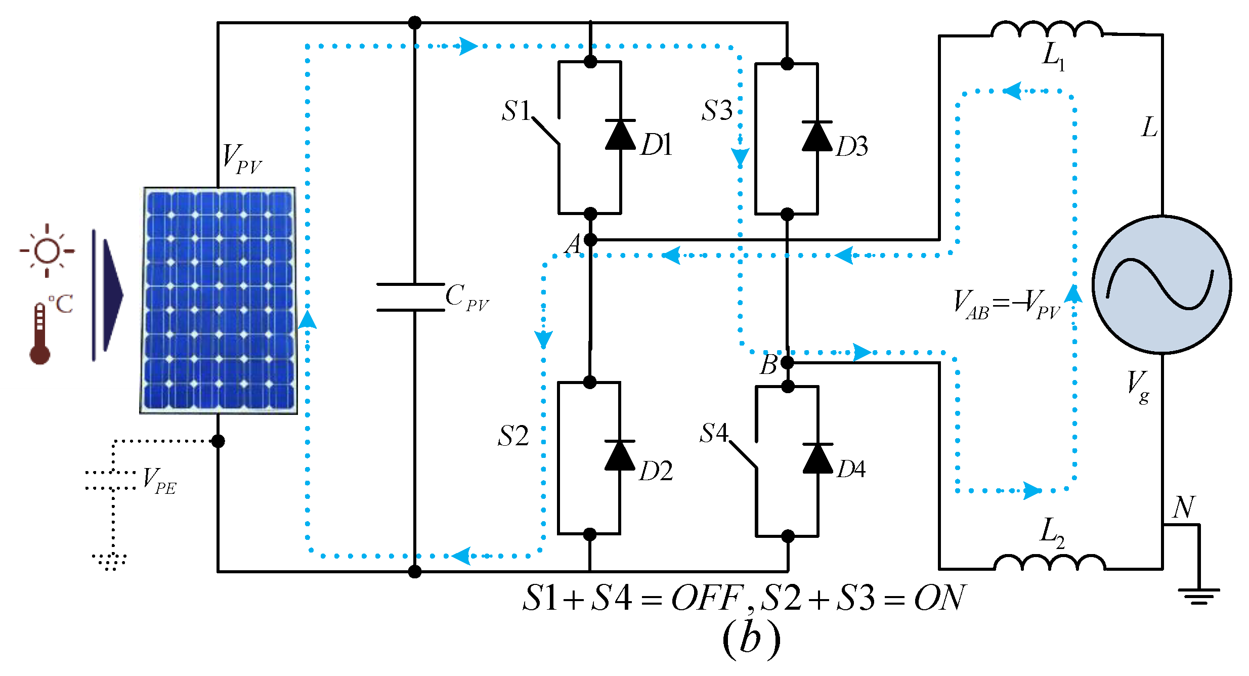
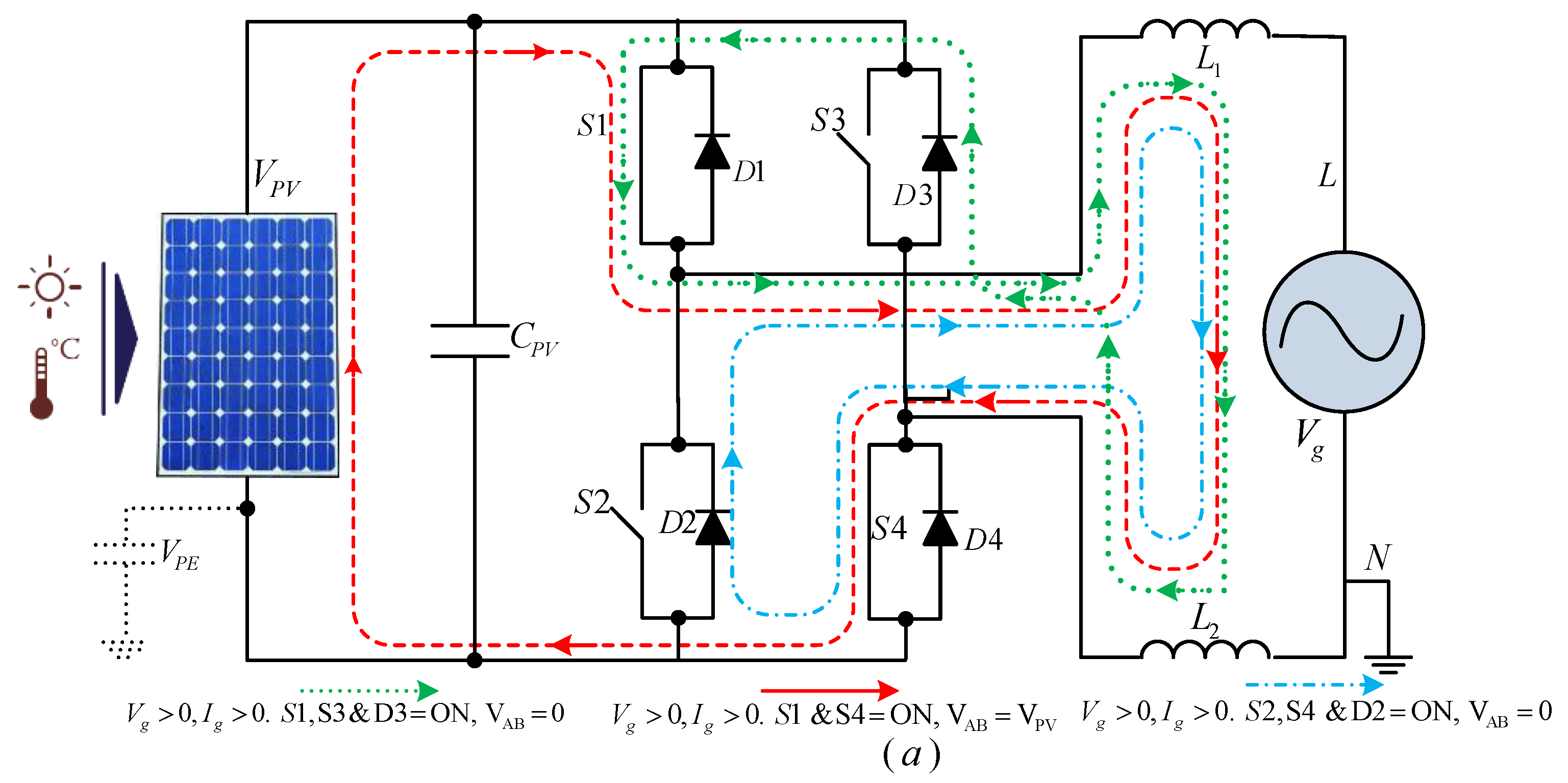
3.1.1. Two Level Modulation
- The diagonal switches are synchronously switched on i.e., S1 with S4 or S2 with S3 at high frequency.
- Zero voltage state at the output is not possible.
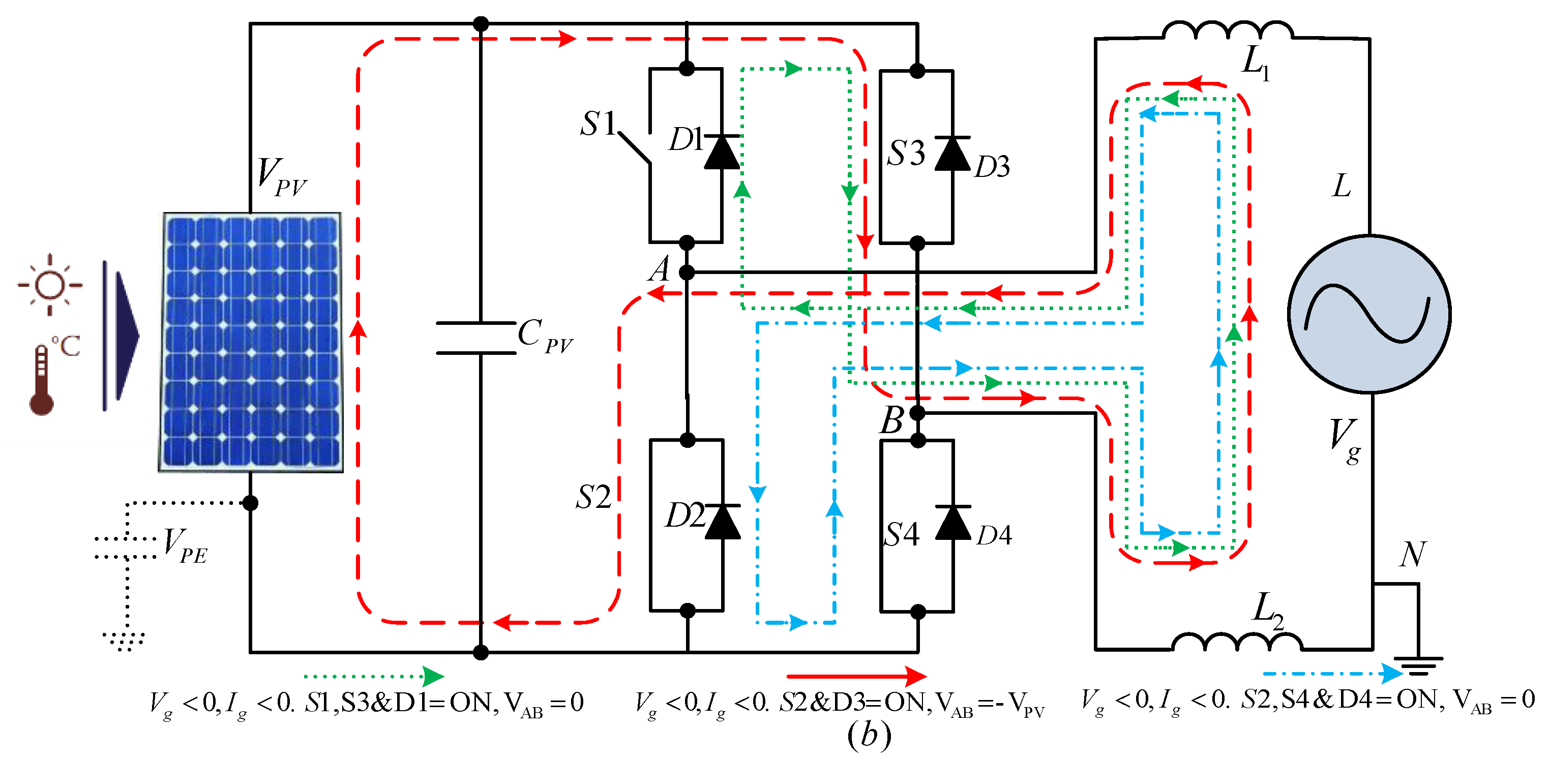
3.1.2. Three-Level Modulation
- Switching of leg, A and leg B at high-frequency with reflected sinusoidal reference.
- Voltage state with zero output is probable: when S1, S3 or S2, S4 are ON.
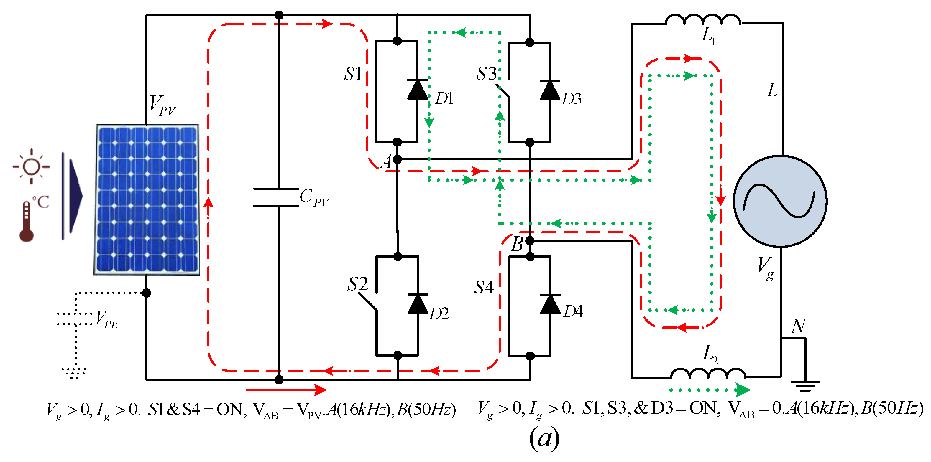
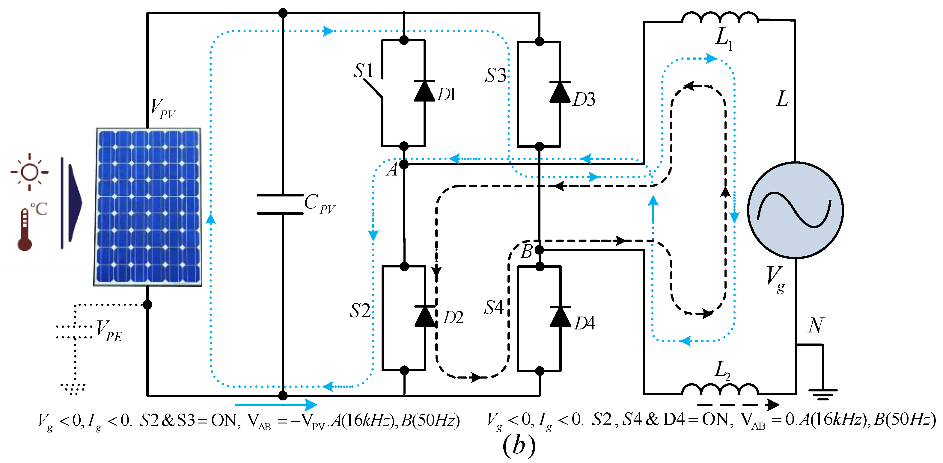
3.1.3. Hybrid Modulation
- At high PWM frequency, leg A is turned on while leg B is turned on at grid low frequency.
- Voltage state with two zero output is possible: when S1, S2 or S3, S4 are ON.
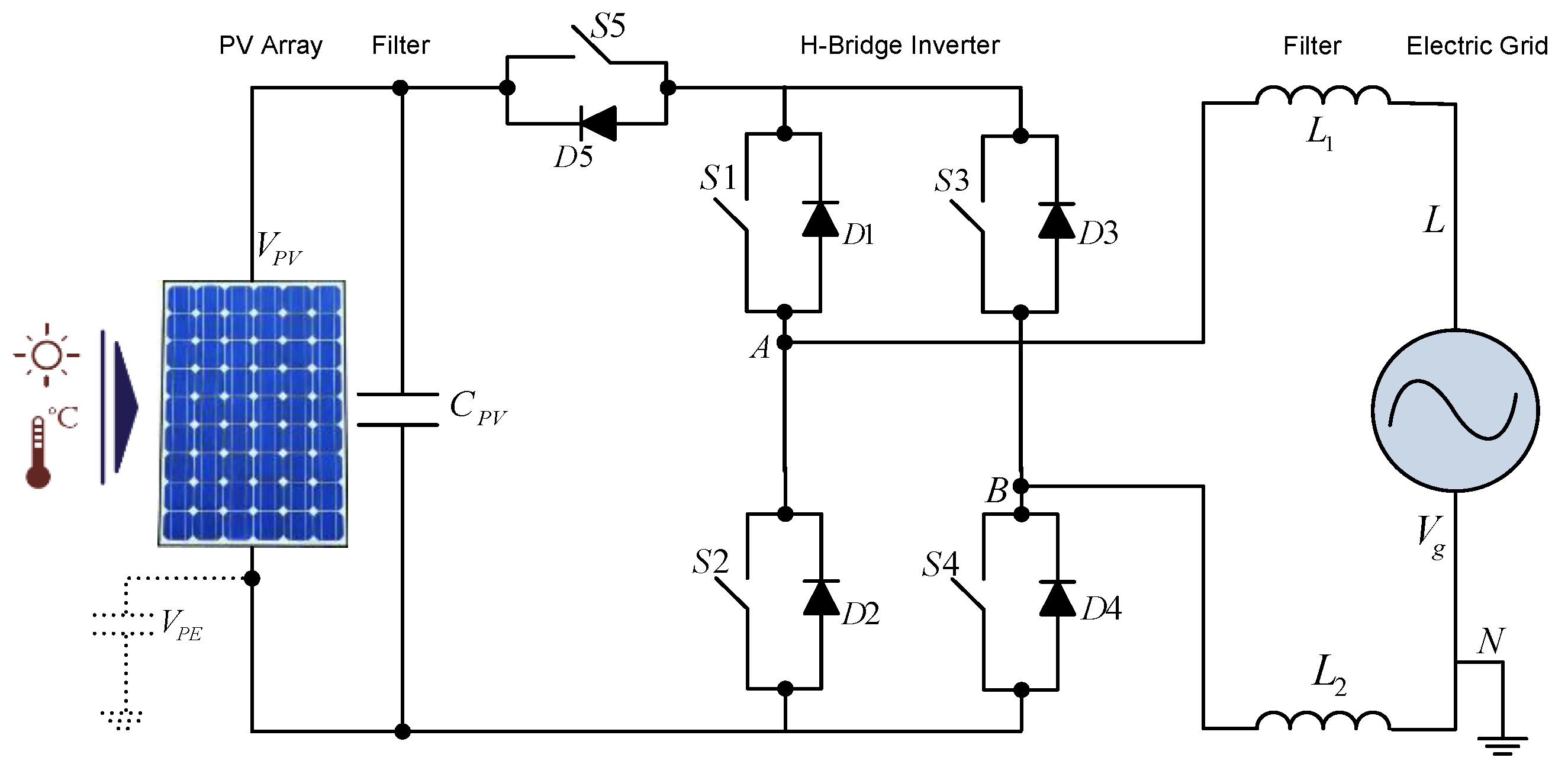
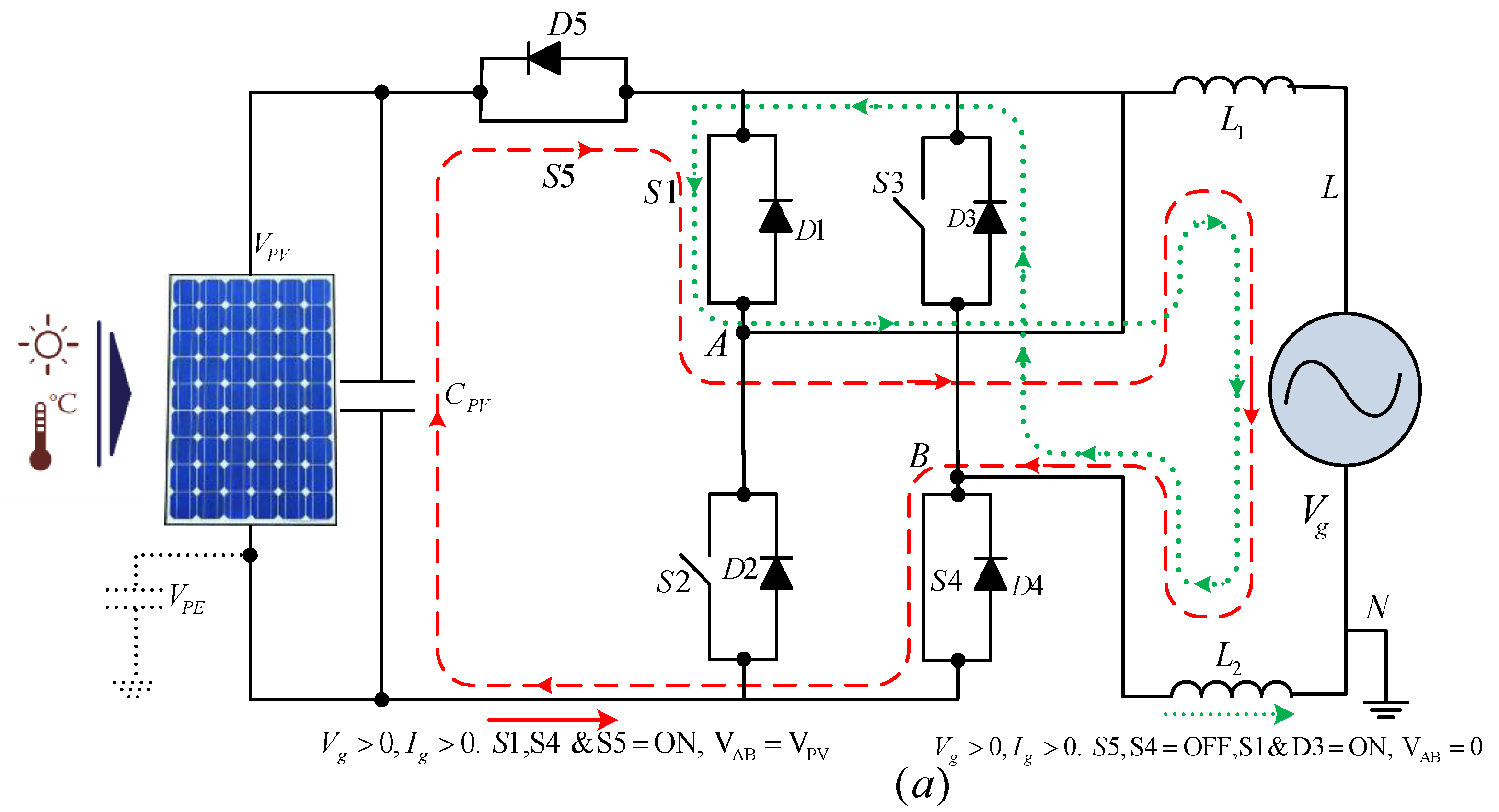
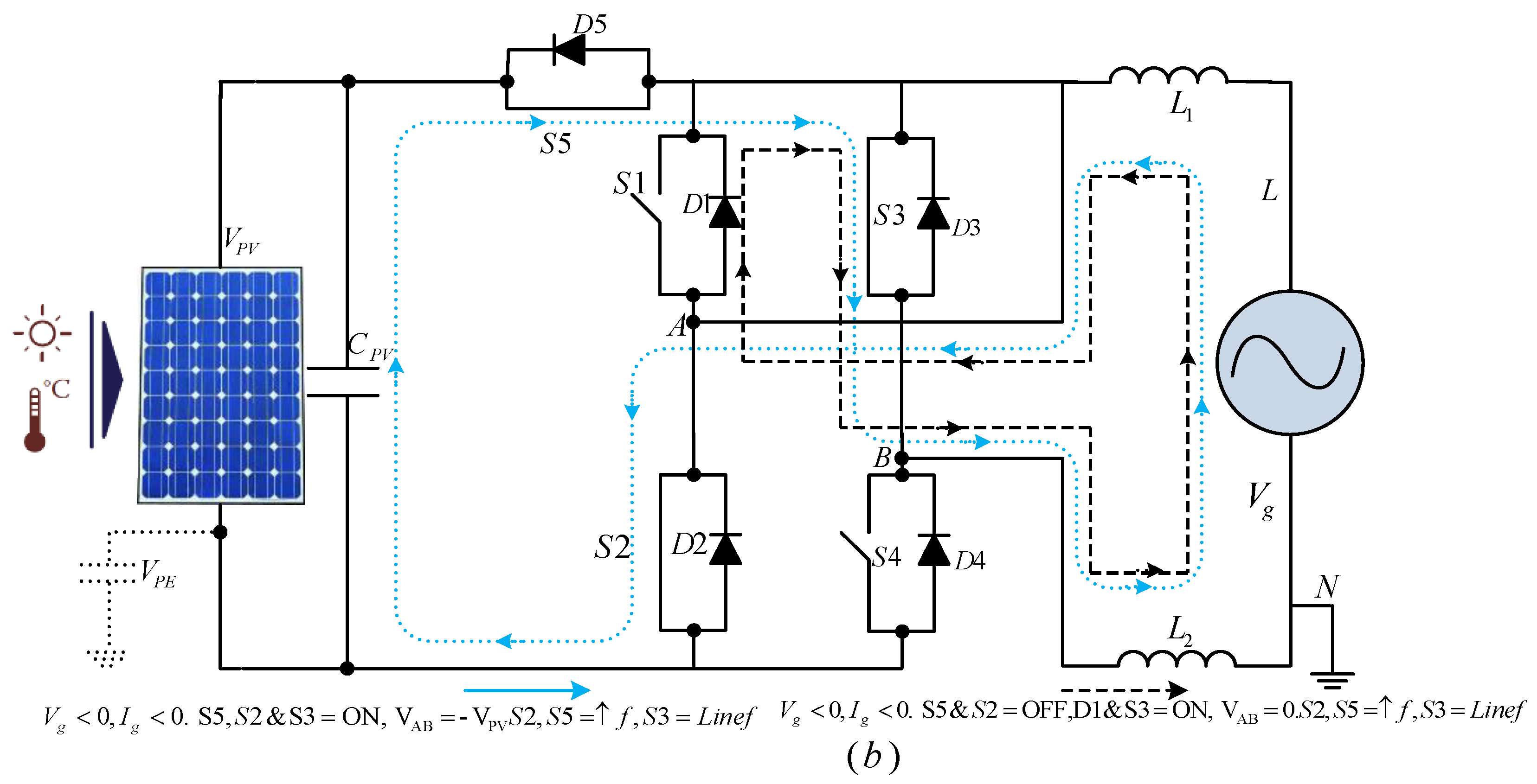
3.2. H5 Inverter (SMA)
- Voltage states with two zero output are possible, i.e., when S5 OFF and S4 (S2) are ON.
- S1 and S3 are switched at grid frequency and S2, S4, and S5 are switched at high frequency.
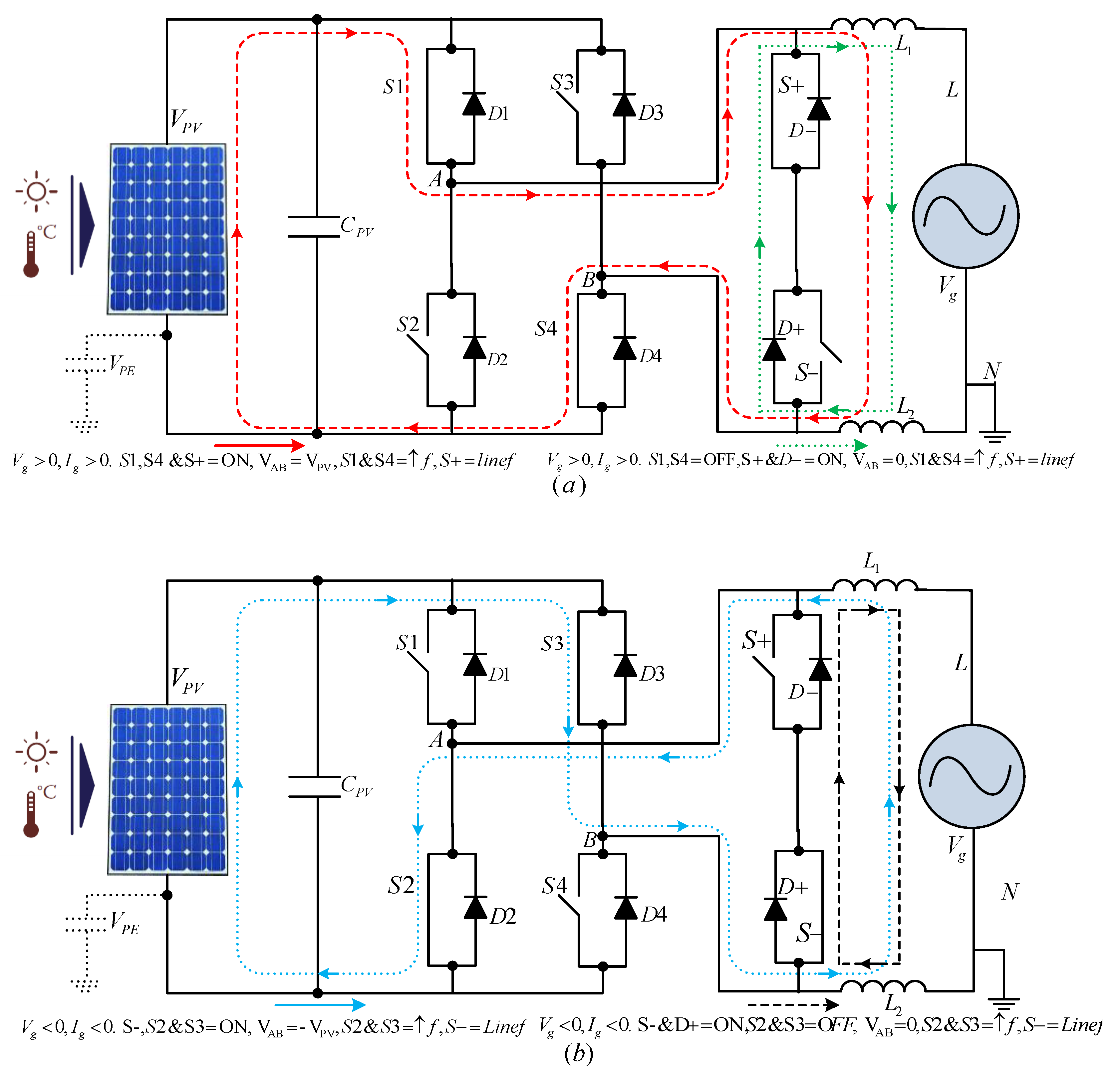
3.3. HERIC Inverter (Sunways)
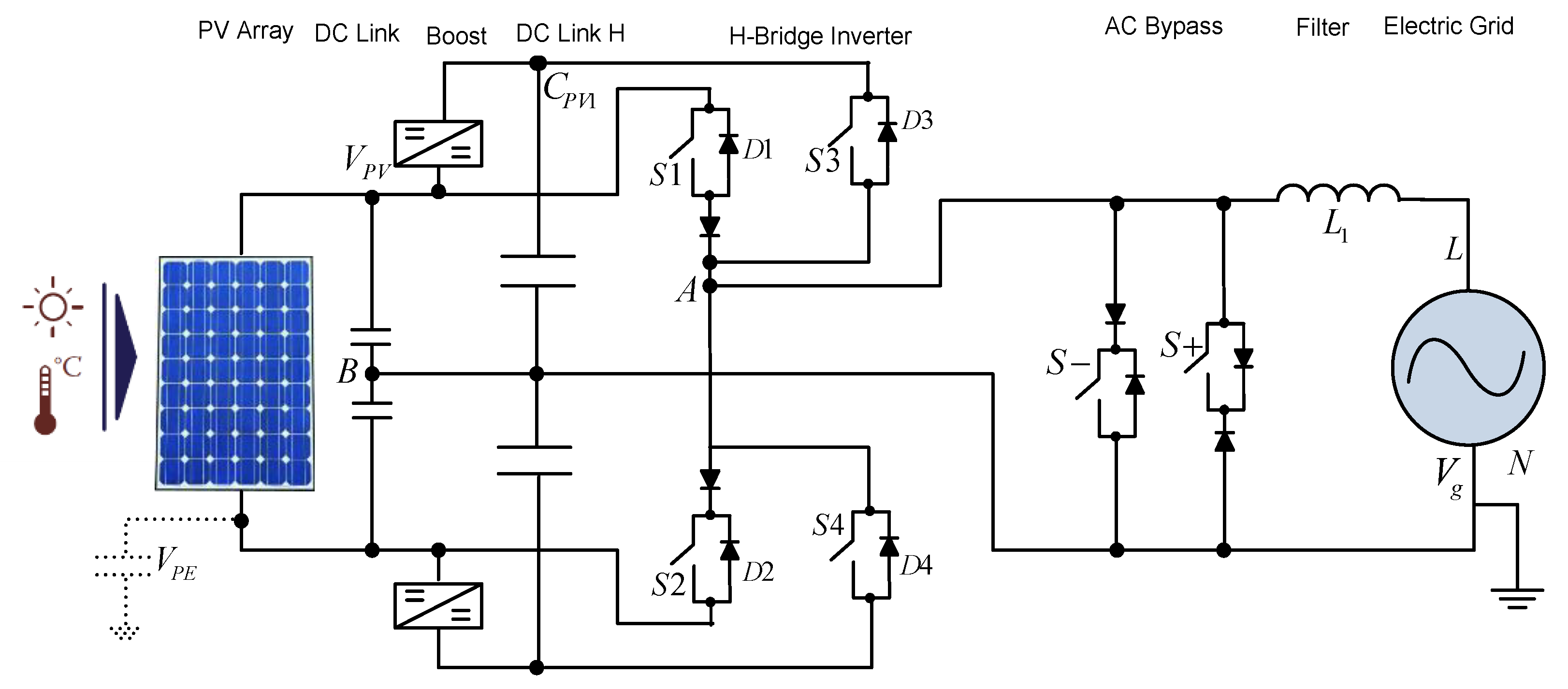
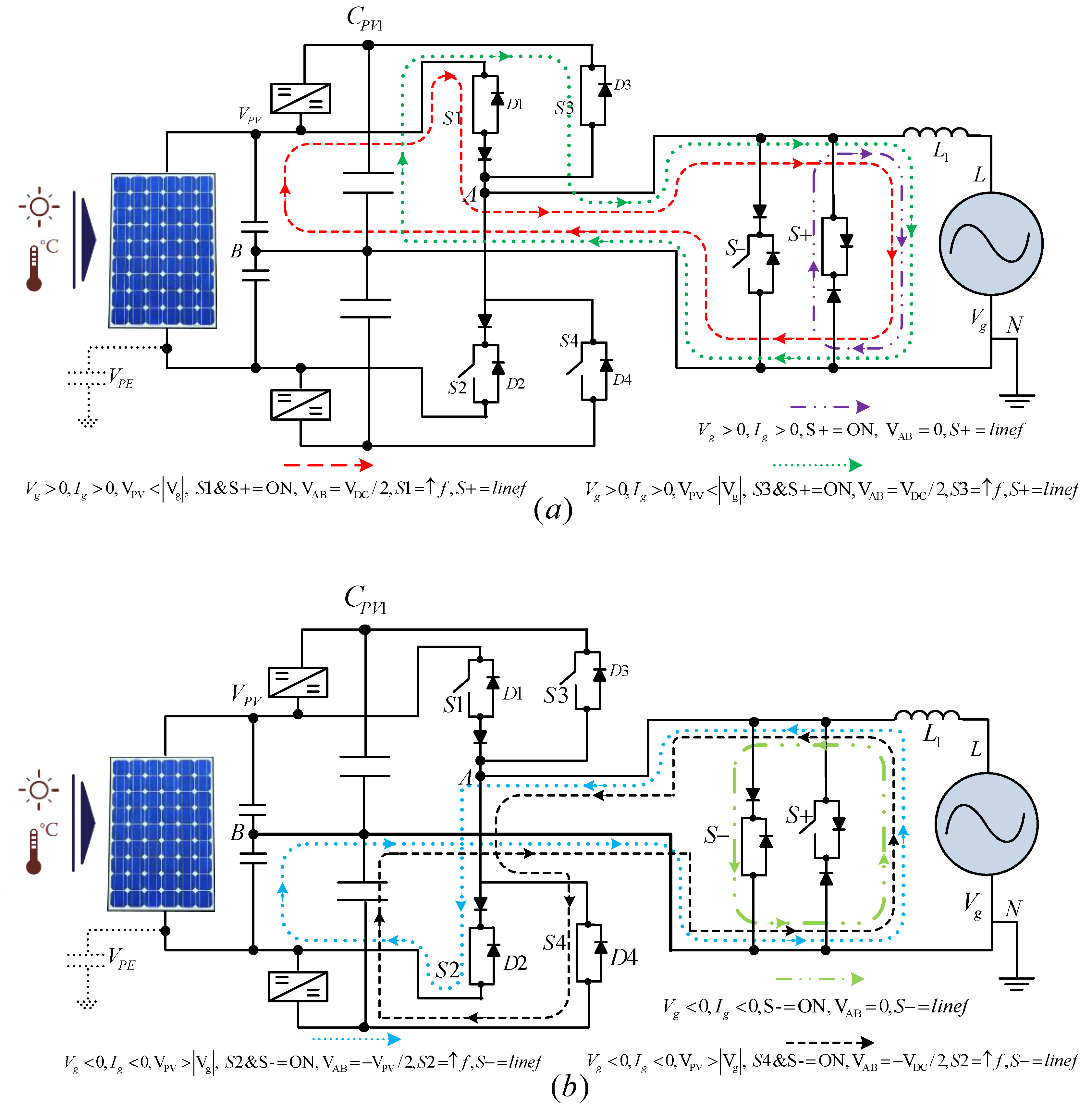
3.4. REFU Inverter
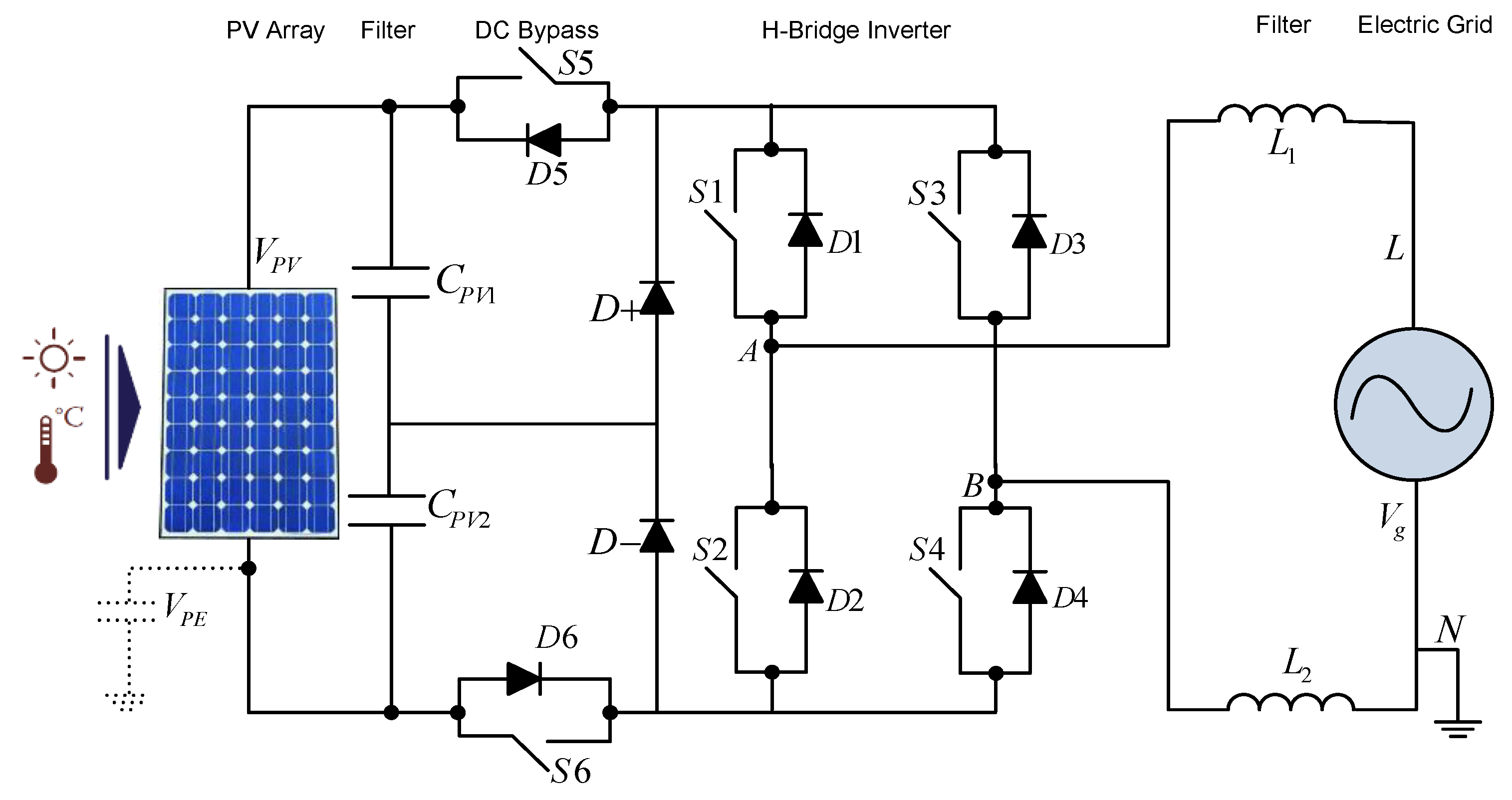
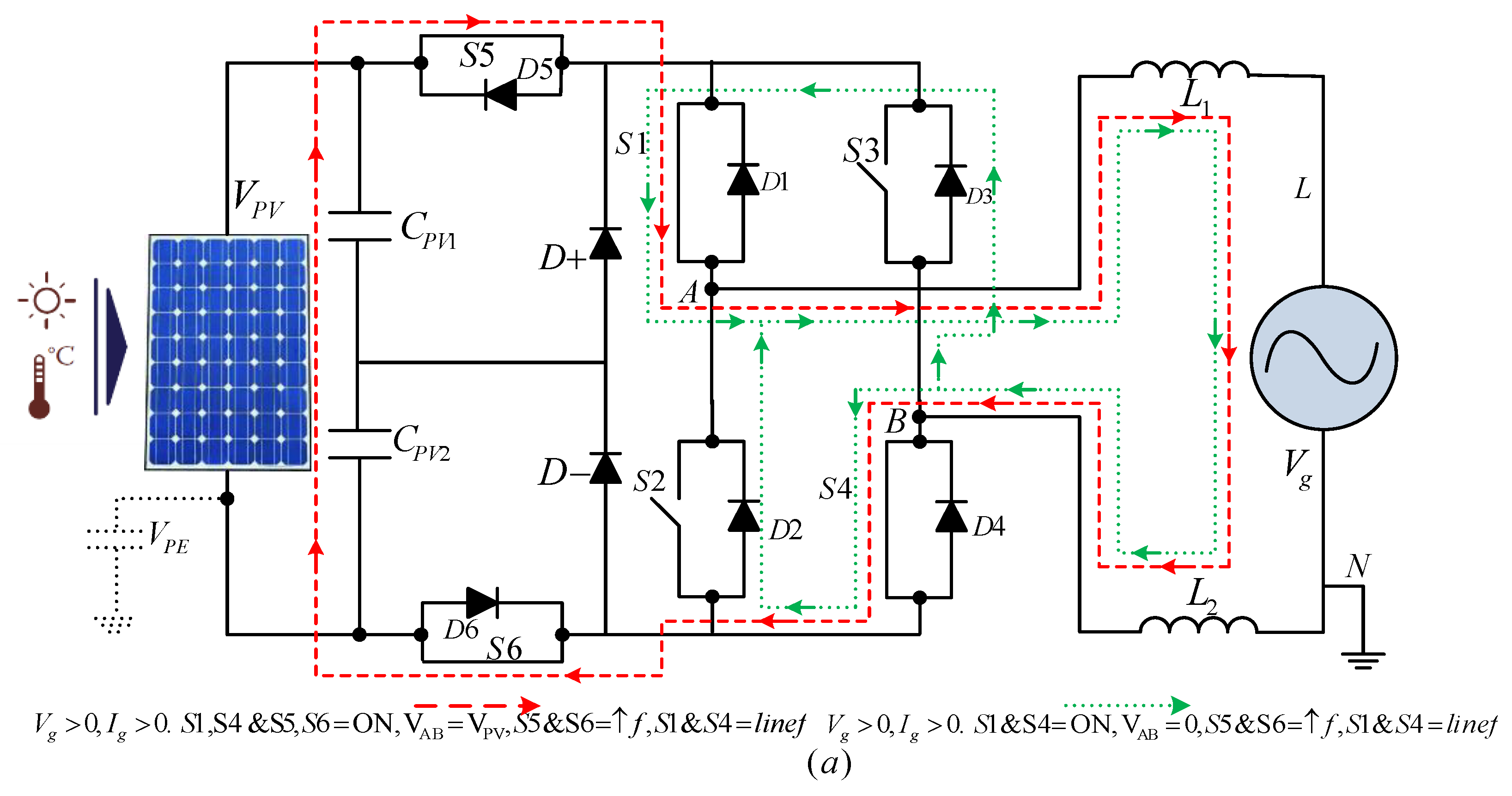
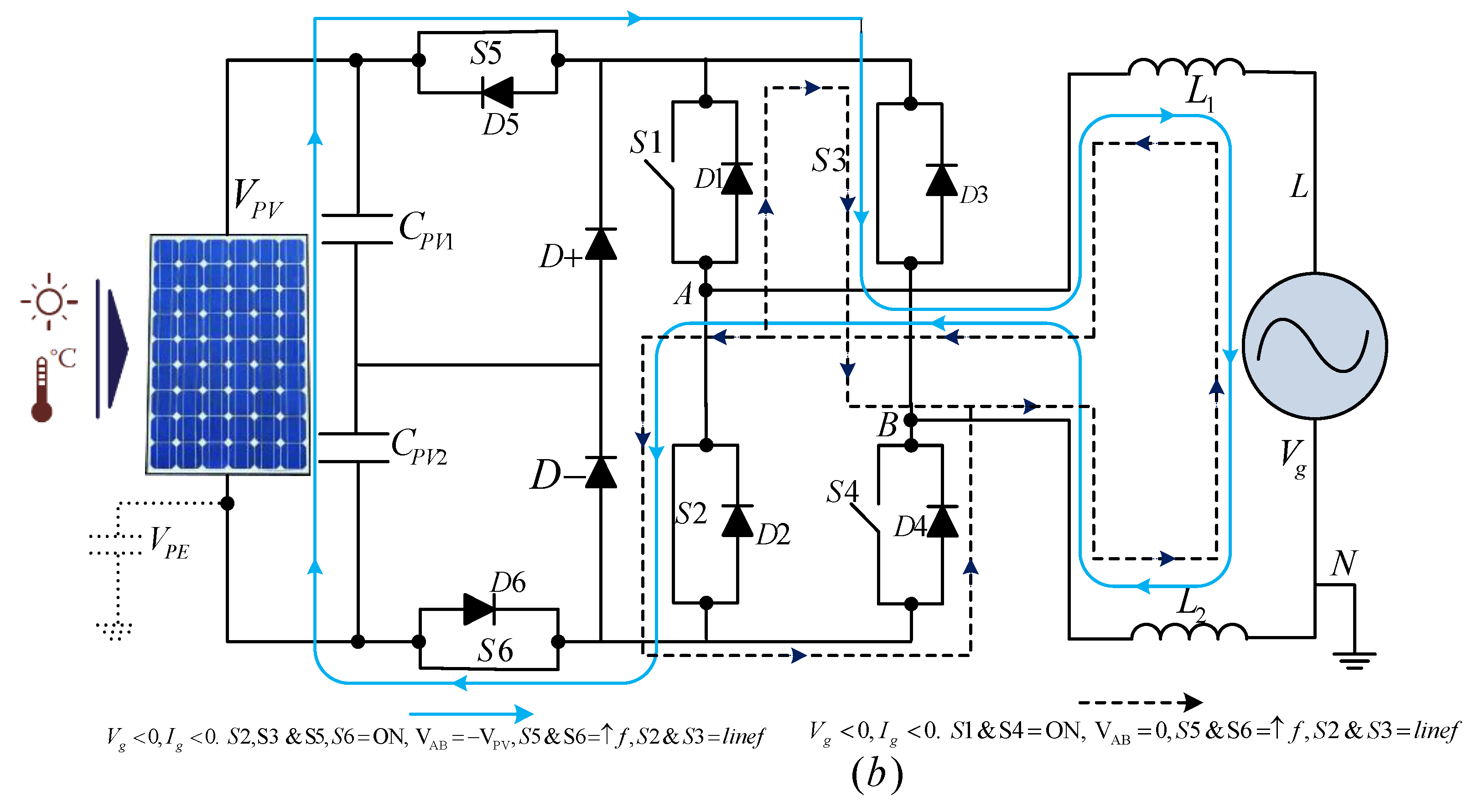
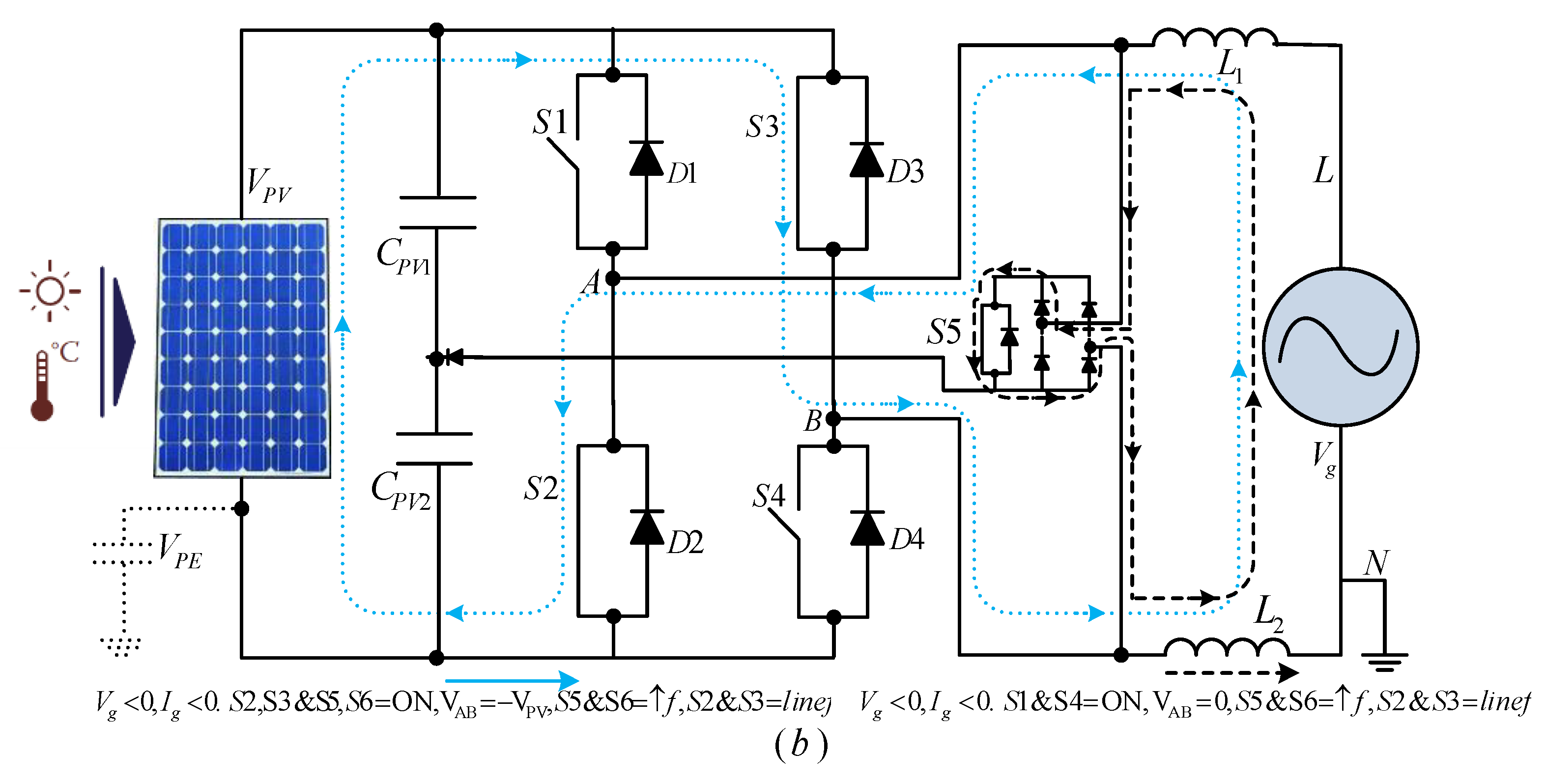
3.5. FB-DCBP (Ingeteam) Inverter
- The switches S1 (S2) or S4 (S3) are turned on at grid frequency while the switching frequency of S5 and S6 are high.
- Zero voltage at the output is attained by turning the DC bypass switches (S5 & S6) OFF. The current divides into two ways, When S5, S6 are turned OFF and S2, S3 are turned ON i.e., (a) The freewheeling diode (D2) of S2 and S4, and (b) S1 and the freewheeling diode (D3) of S3. Consequently, no switching losses appear as S2 and S3 are turned ON with no current. The current path during zero voltage state for negative grid current will be S2-D4 or S3-D1, while for positive grid currents will be S1-D3 or S4-D2. To the half of the DC-link voltage, for clamping the bypass switches D+ and D- are used [10].
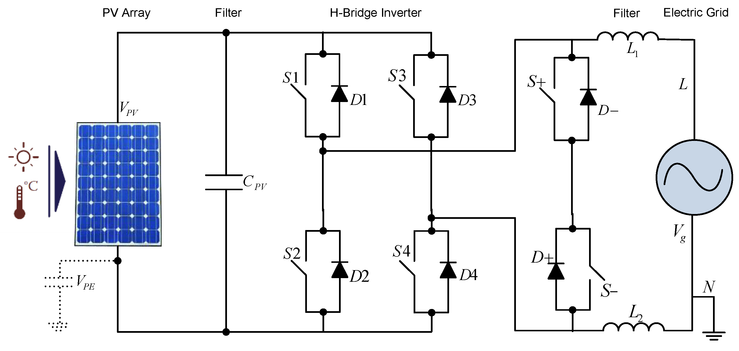
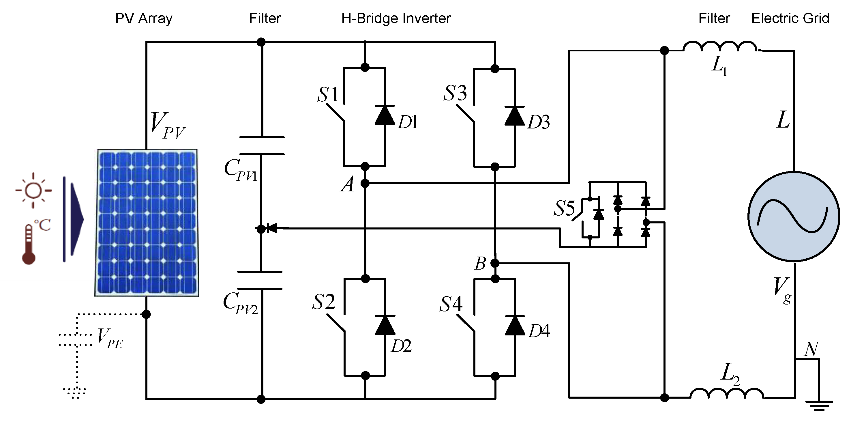
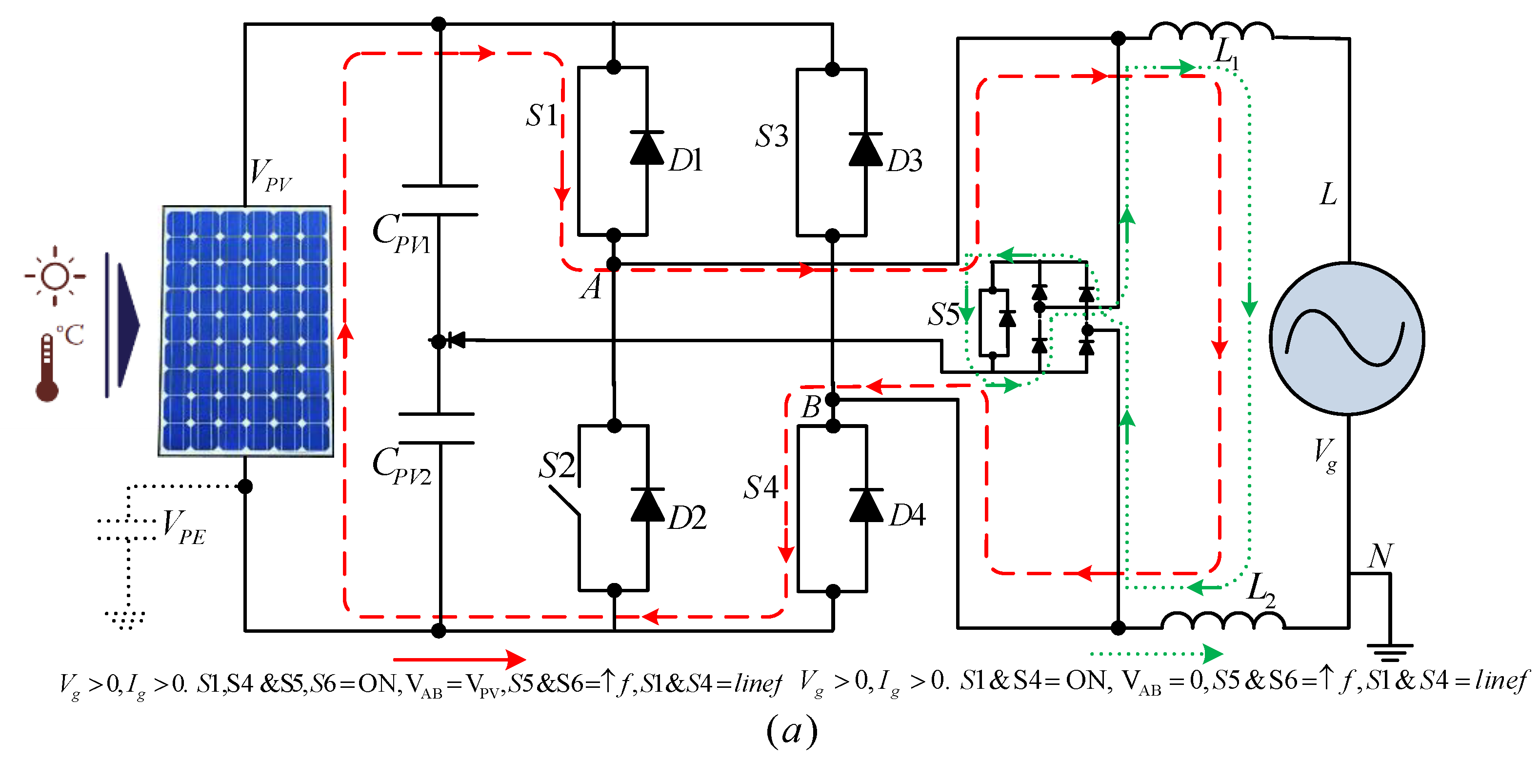
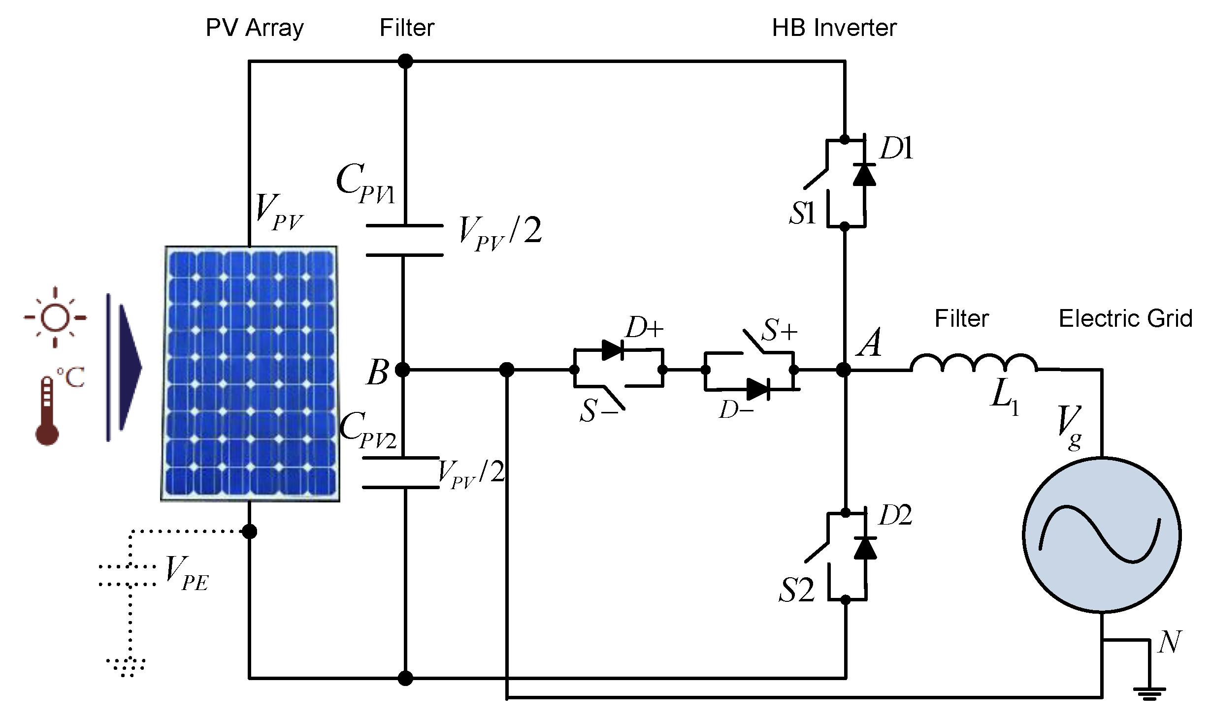
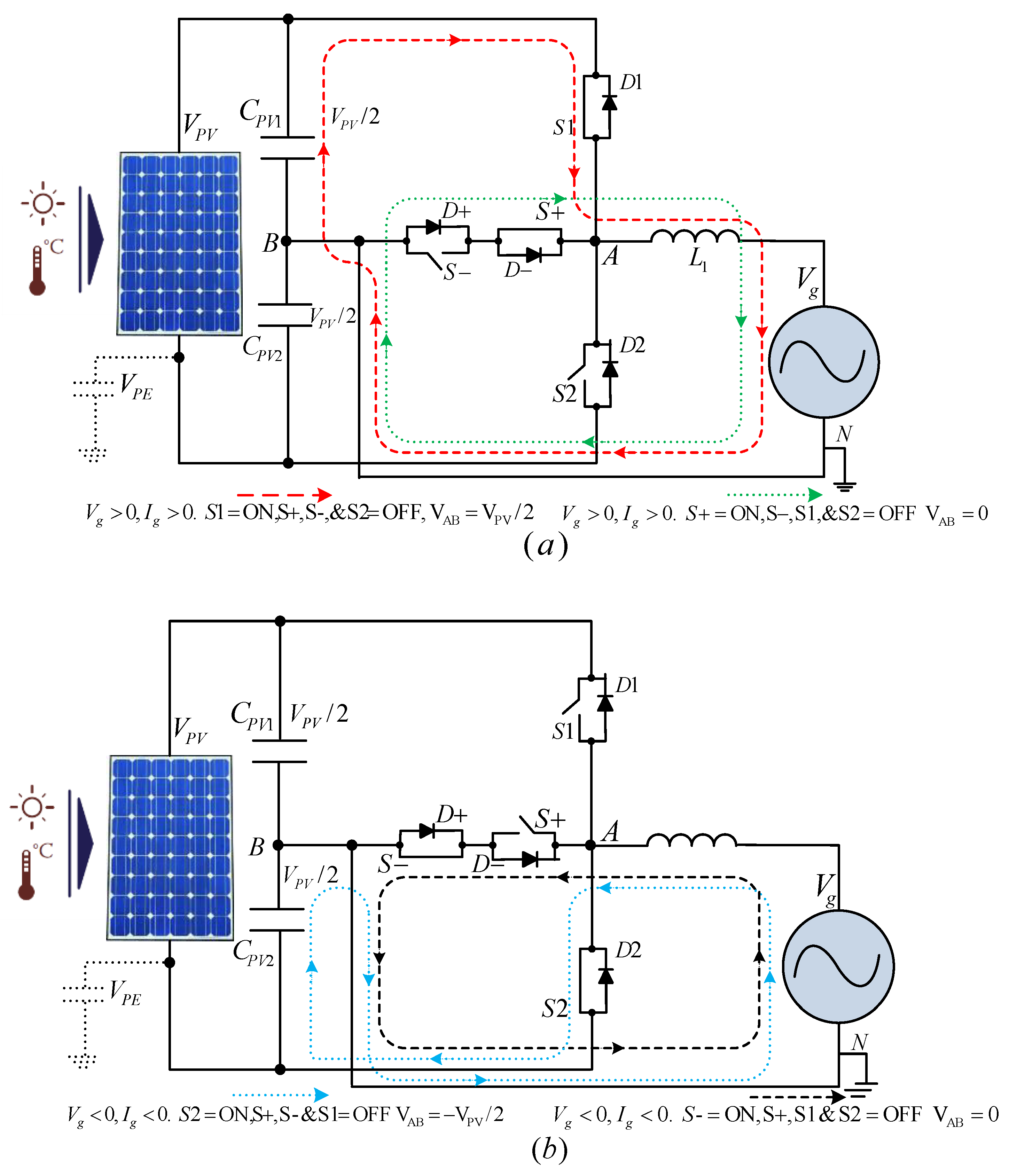
3.6. Full-Bridge Zero Voltage Rectifier-(FB-ZVR) Inverter
- Like in bipolar modulation, the switches are diagonally switched in FB. The zero state is introduced by turning off all switches of the bridge except S5.
3.7. FB-Derived Inverter Topologies: An Overview
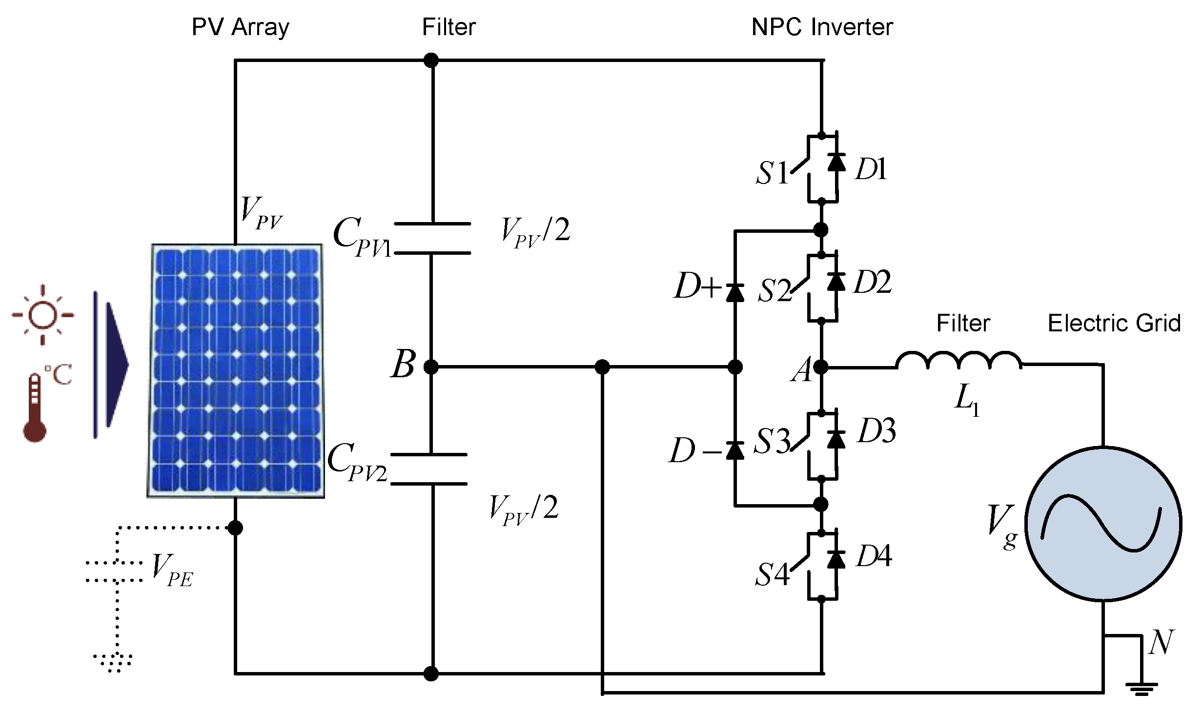
4. NPC Based Inverter Structures
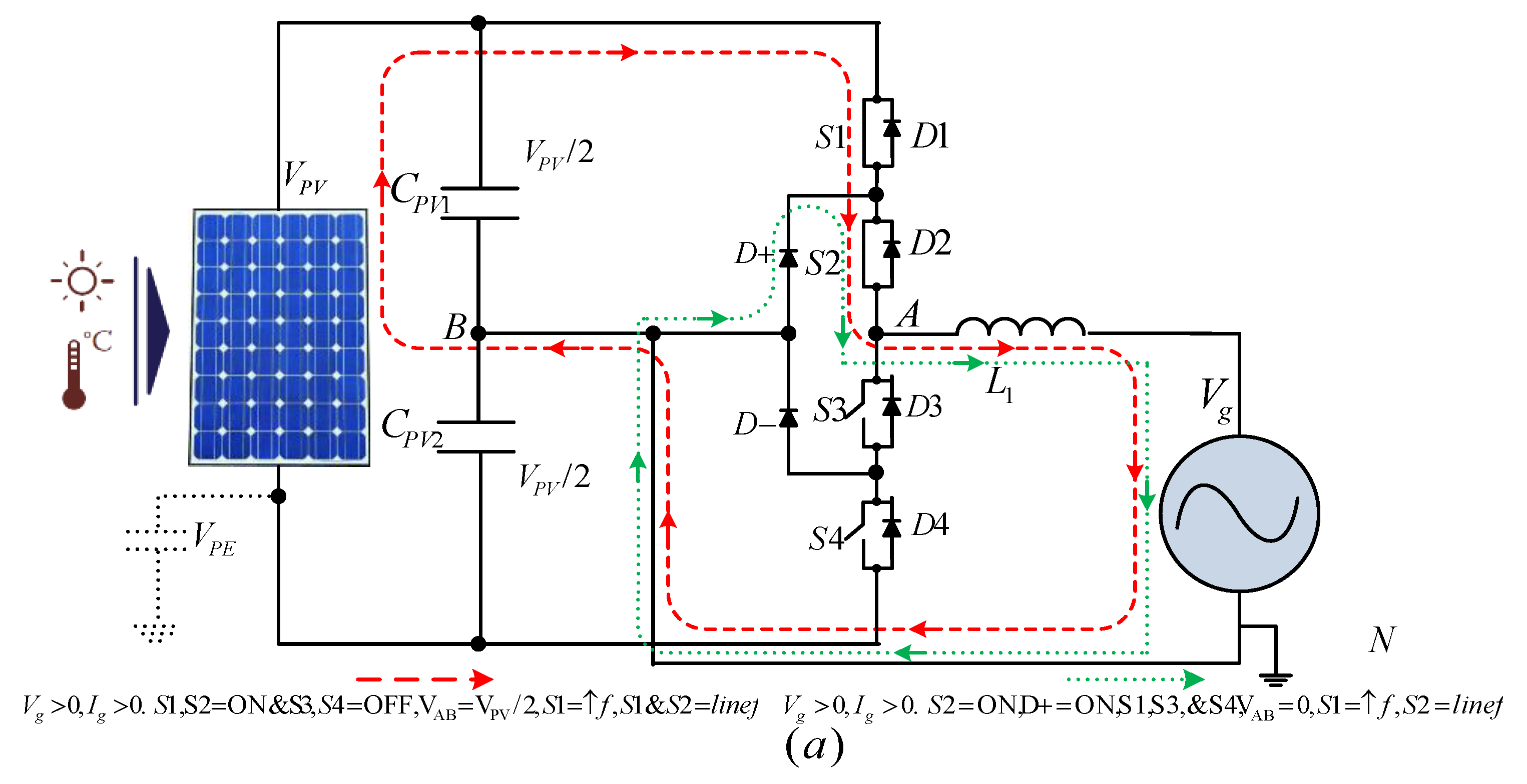
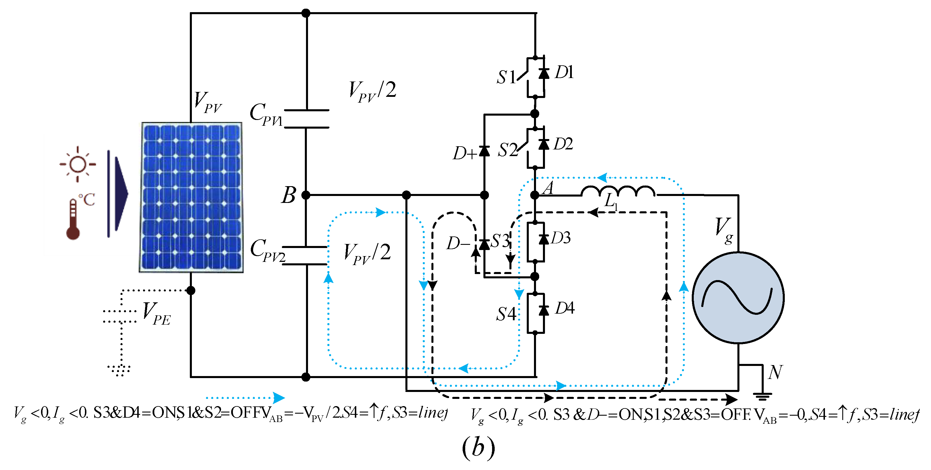
4.1. NPC Half Bridge Inverter
4.2. Conergy NPC Inverter
4.3. Miscellaneous Topologies
4.4. NPC-Derived Inverter Topologies: An Overview
5. Transformerless PV Inverters: Comparative and Characteristics Overview
5.1. Parameter Comparison
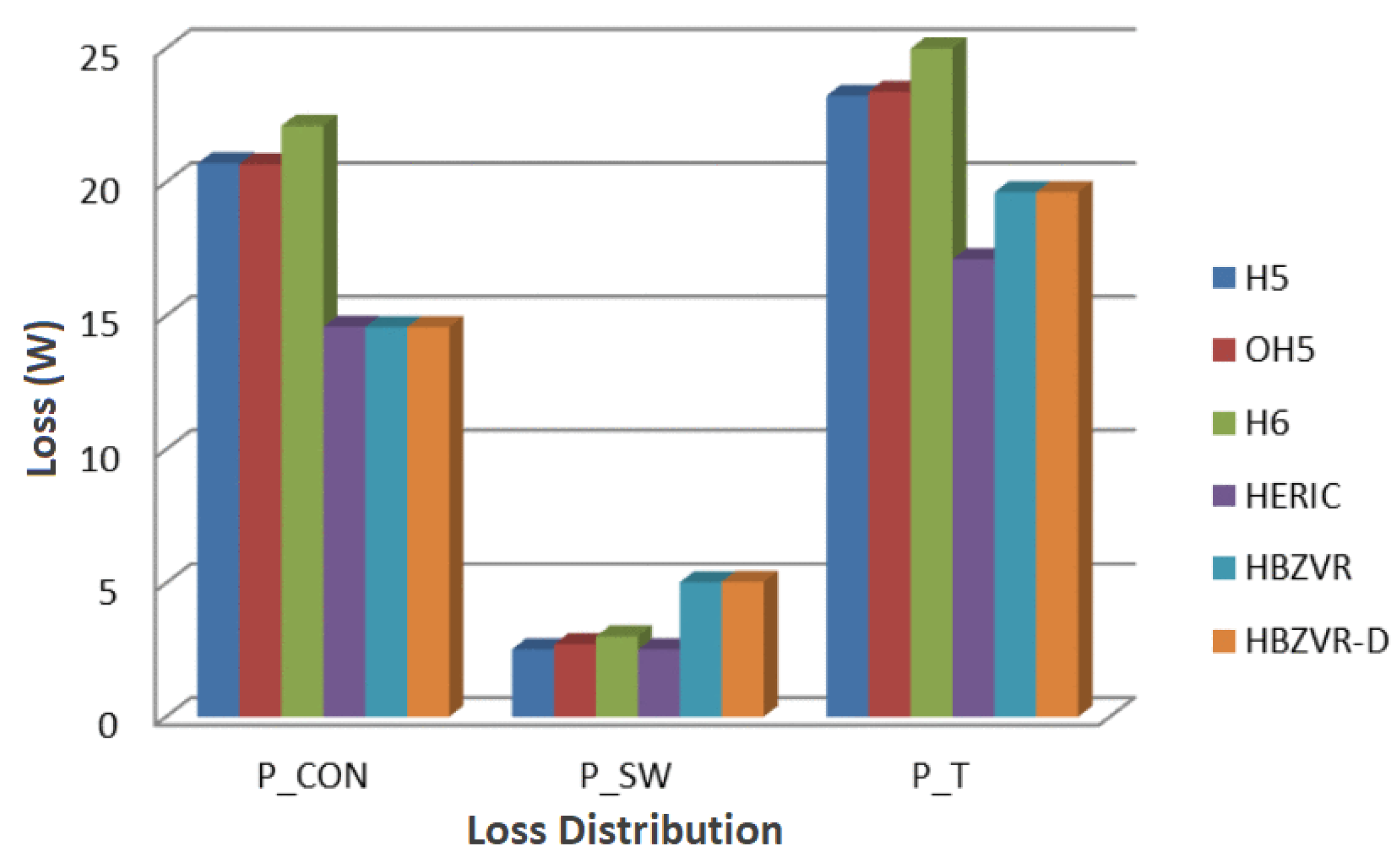
5.2. Loss Analysis
6. Control Structure for Single Phase and Three Phase Grid Connected Systems
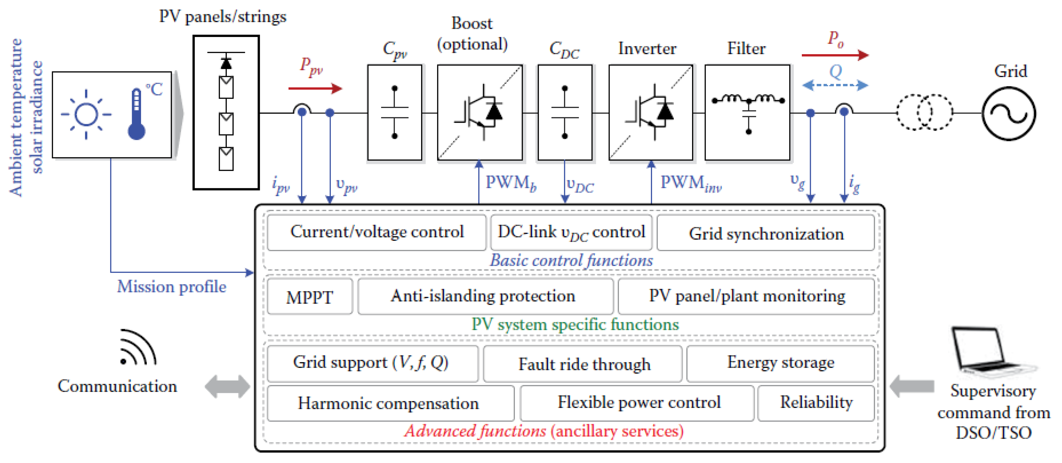
6.1. Generic Control Structure
- (a)
- MPP control: MPP control is used to extract maximum power from solar PV modules.
- (b)
- Inverter control: This control is use to (a) inject quality power and stay synchronize with the grid, (b) control the power flow to the grid and (c) maintain DC link voltage at desired level.
6.2. Single phase and Three Phase Control Structure
7. Conclusions and Future Work
Author Contributions
Acknowledgments
Conflicts of Interest
References
- Hassaine, L.; Olias, E.; Quintero, J.; Salas, V. Overview of power inverter topologies and control structures for grid connected photovoltaic systems. Renew. Sustain. Energy Rev. 2014, 30, 796–807. [Google Scholar] [CrossRef]
- Ellabban, O.; Abu-Rub, H.; Blaabjerg, F. Renewable energy resources: Current status, future prospects and their enabling technology. Renew. Sustain. Energy Rev. 2014, 39, 748–764. [Google Scholar] [CrossRef]
- Zeb, K.; Uddin, W.; Khan, M.A.; Ali, Z.; Ali, M.U.; Christofides, N.; Kim, H.J. A comprehensive review on inverter topologies and control strategies for grid connected photovoltaic system. Renew. Sustain. Energy Rev. 2018, 94, 1120–1141. [Google Scholar] [CrossRef]
- Sawin, J.L.; Seyboth, K.; Sverrisson, F. Renewables 2016: Global Status Report; REN21: Ottawa, ON, Canada, 2016. [Google Scholar]
- Wirth, H. Recent Facts about Photovoltaics in Germany; Fraunhofer Institute for Solar Energy Systems ISE: Fraunhofer, Germany, 2015. [Google Scholar]
- SolarPower Europe. Global Market Outlook for Solar Power 2015–2019. 2014. Available online: https://helapco.gr/pdf/Global_Market_Outlook_2015_-2019_lr_v23.pdf (accessed on 24 July 2018).
- Wind Energy and Solar | Installed GW Capacity-Global and by Country. Available online: http://www.fi-powerweb.com/Renewable-Energy.html (accessed on 20 July 2018).
- Blaabjerg, F.; Ma, K.; Yang, Y. Power electronics-The key technology for renewable energy systems integration. In Proceedings of the 2015 International Conference on Renewable Energy Research and Applications (ICRERA), Palermo, Italy, 22–25 November 2015. [Google Scholar]
- Van Wyk, J.D.; Lee, F.C. On a Future for Power Electronics. Emerg. Sel. Top. Power Electron. IEEE J. 2013, 1, 59–72. [Google Scholar] [CrossRef]
- Kjaer, S.B.; Pedersen, J.K.; Blaabjerg, F. A review of single-phase grid-connected inverters for photovoltaic modules. IEEE Trans. Ind. Appl. 2005, 41, 1292–1306. [Google Scholar] [CrossRef]
- Bergveld, H.J.; Büthker, D.; Castello, C.; Doorn, T.; de Jong, A.; van Otten, R.; de Waal, K. Module-Level DC/DC Conversion for Photovoltaic Systems: The Delta-Conversion Concept. IEEE Trans. Power Electron. 2013, 28, 2005–2013. [Google Scholar] [CrossRef]
- Liu, B.; Duan, S.; Cai, T. Photovoltaic DC-Building-Module-Based BIPV System-Concept and Design Considerations. Power Electron. IEEE Trans. 2011, 26, 1418–1429. [Google Scholar] [CrossRef]
- Sera, D.; Mathe, L.; Blaabjerg, F. Distributed control of PV strings with Module Integrated Converters in presence of a central MPPT. In Proceedings of the 2014 IEEE Energy Conversion Congress and Exposition (ECCE), Pittsburgh, PA, USA, 14–18 September 2014. [Google Scholar]
- Eltawil, M.A.; Zhao, Z. Grid-connected photovoltaic power systems: Technical and potential problems-A review. Renew. Sustain. Energy Rev. 2010, 14, 112–129. [Google Scholar] [CrossRef]
- Spertino, F.; Graditi, G. Power conditioning units in grid-connected photovoltaic systems: A comparison with different technologies and wide range of power ratings. Sol. Energy 2014, 108, 219–229. [Google Scholar] [CrossRef]
- Zeb, K.; Ali, Z.; Saleem, K.; Uddin, W.; Javed, M.A.; Christofides, N. Indirect field-oriented control of induction motor drive based on adaptive fuzzy logic controller. Electr. Eng. 2017, 99, 803–815. [Google Scholar] [CrossRef]
- Romero-Cadaval, E.; Spagnuolo, G.; Franquelo, L.G.; Ramos-Paja, C.A.; Suntio, T.; Xiao, W.M. Grid-connected photovoltaic generation plants: Components and operation. IEEE Ind. Electron. Mag. 2013, 7, 6–20. [Google Scholar] [CrossRef] [Green Version]
- Meinhardt, M.; Cramer, G. Multi-String-Converter: The next step in Evolution of String-Converter Technology. In Proceedings of the 9th European Conference on Power Electronics and Applications, Graz, Austria, 15 March 2001. [Google Scholar]
- Morjaria, M.; Anichkov, D.; Chadliev, V.; Soni, S. A Grid-Friendly Plant: The Role of Utility-Scale Photovoltaic Plants in Grid Stability and Reliability. IEEE Power Energy Mag. 2014, 12, 87–95. [Google Scholar] [CrossRef]
- Zeb, K.; Ayesha; Haider, A.; Uddin, W.; Qureshi, M.B.; Mehmood, C.A.; Jazlan, A.; Sreeram, V. Indirect Vector Control of Induction Motor using Adaptive Sliding Mode Controller. In Proceedings of the 2016 Australian Control Conference (AuCC), Newcastle, NSW, Australia, 3–4 Novermber 2016. [Google Scholar]
- Li, Q.; Wolfs, P. A review of the single phase photovoltaic module integrated converter topologies with three different DC link configurations. IEEE Trans. Power Electron. 2008, 23, 1320–1333. [Google Scholar]
- Yang, Y.; Enjeti, P.; Blaabjerg, F.; Wang, H. Wide-scale adoption of photovoltaic energy: Grid code modifications are explored in the distribution grid. IEEE Ind. Appl. Mag. 2015, 21, 21–31. [Google Scholar] [CrossRef]
- He, J.; Yi, L.; Wang, X.; Wang, J. Research on deadbeat control of a three-level grid-connected inverter based on αβ transform. Procedia Eng. 2011, 23, 397–402. [Google Scholar]
- Kahrobaeian, A.; Farhangi, S. Stationary frame current control of single phase grid connected PV inverters. In Proceedings of the 2010 1st Power Electronic & Drive Systems & Technologies Conference (PEDSTC), Tehran, Iran, 17–18 February 2010. [Google Scholar]
- Kaundinya, D.P.; Balachandra, P.; Ravindranath, N.H. Grid-connected versus stand-alone energy systems for decentralized power-A review of literature. Renew. Sustain. Energy Rev. 2009, 13, 2041–2050. [Google Scholar] [CrossRef]
- Kazmierkowski, M.P.; Krishnan, R.; Blaabjerg, F.; Irwin, J.D. Control in Power Electronics: Selected Problems; Academic Press: Cambridge, MA, USA, 2002. [Google Scholar]
- Kerekes, T.; Teodorescu, R.; Liserre, M.; Klumpner, C.; Sumner, M. Evaluation of three-phase transformerless photovoltaic inverter topologies. IEEE Trans. Power Electron. 2009, 24, 2202–2211. [Google Scholar] [CrossRef]
- Özkan, Z.; Hava, A.M. Classification of grid connected transformerless PV inverters with a focus on the leakage current characteristics and extension of topology families. J. Power Electron. 2015, 15, 256–267. [Google Scholar] [CrossRef]
- Blaabjerg, F.; Ionel, D.M. Renewable Energy Devices and Systems with Simulations in MATLAB and ANSYS; CRC Press: London, UK, 2017. [Google Scholar]
- Teodorescu, R.; Liserre, M.; Rodríguez, P. Grid Converters for Photovoltaic and Wind Power Systems; John Willey and Son, Ltd.: Chichester, UK, 2010. [Google Scholar]
- Ahmad, Z.; Singh, S.N. Comparative analysis of single phase transformerless inverter topologies for grid connected PV system. Sol. Energy 2017, 149, 245–271. [Google Scholar] [CrossRef]
- Yuan, X.; Merk, W.; Stemmler, H.; Allmeling, J. Stationary-frame generalized integrators for current control of active power filters with zero steady-state error for current harmonics of concern under unbalanced and distorted operating conditions. IEEE Trans. Industry Appl. 2002, 38, 523–532. [Google Scholar] [CrossRef] [Green Version]
- Zhang, R.; Cardinal, M.; Szczesny, P.; Dame, M. A Grid Simulator with control of single-phase power converters in D-Q rotating frame. In Proceedings of the 2002 IEEE 33rd Annual IEEE Power Electronics Specialists Conference. Proceedings (Cat. No. 02CH37289), Cairns, Australia, 23–27 June 2002. [Google Scholar]
- Zhu, H.; Arnet, B.; Haines, L.; Shaffer, E.; Lai, J.-S. Grid synchronization control without AC voltage sensors. In Proceedings of the Eighteenth Annual IEEE Applied Power Electronics Conference and Exposition, 2003 (APEC’03), Miami Beach, FL, USA, 9–13 February 2003. [Google Scholar]
- Zmood, D.N.; Holmes, D.G. Stationary frame current regulation of PWM inverters with zero steady-state error. IEEE Trans. Power Electron. 2003, 18, 814–822. [Google Scholar] [CrossRef]
- Hamrouni, N.; Jraidi, M.; Chérif, A. New control strategy for 2-stage grid-connected photovoltaic power system. Renew. Energy 2008, 33, 2212–2221. [Google Scholar] [CrossRef]
- Yang, B.; Li, W.; Gu, Y.; Cui, W.; He, X. Improved transformerless inverter with common-mode leakage current elimination for a photovoltaic grid-connected power system. IEEE Trans. Power Electron. 2012, 22, 752–762. [Google Scholar] [CrossRef]
- Hong, F.; Shan, R.Z.; Wang, H.Z. Analysis and calculation of inverter power loss. IEEE Std 1547.1-2005. IEEE Standards conformance Test Procedure for equipment interconnecting distributed resources with electric power system. Pro. CSEE 2008, 28, 72–78. [Google Scholar]
- Mekhilef, S.; Islam, M. H6-type transformerless single-phase inverter for grid-tied photovoltaic system. IET Power Electron. 2015, 8, 636–644. [Google Scholar]
- Islam, M.; Mekhilef, S.; Hasan, M. Single phase transformerless inverter topologies for grid-tied photovoltaic system: A review. Renew. Sustain. Energy Rev. 2015, 45, 69–86. [Google Scholar] [CrossRef]
- Ji, B.; Wang, J.; Zhao, J. High-efficiency single-phase transformerless PV H6 inverter with hybrid modulation method. IEEE Trans. Ind. Electron. 2013, 60, 2104–2115. [Google Scholar] [CrossRef]
- Chatterjee, S.; Kumar, P.; Chatterjee, S. A techno-commercial review on grid connected photovoltaic system. Renew. Sustain. Energy Rev. 2018, 81, 2371–2397. [Google Scholar] [CrossRef]
- Patrao, I.; Figueres, E.; González-Espín, F.; Garcerá, G. Transformerless topologies for grid-connected single-phase photovoltaic inverters. Renew. Sustain. Energy Rev. 2011, 15, 3423–3431. [Google Scholar] [CrossRef] [Green Version]
- Calais, M.; Agelidis, V.G.; Meinhardt, M. Multilevel converters for single-phase grid connected photovoltaic systems: An overview. Sol. Energy 1999, 66, 325–335. [Google Scholar] [CrossRef]
- Xue, Y.; Manjrekar, M. A new class of single-phase multilevel inverters. In Proceedings of the 2nd International Symposium on Power Electronics for Distributed Generation Systems, Hefei, China, 16–18 June 2010. [Google Scholar]
- Li, W.; Gu, Y.; Luo, H.; Cui, W.; He, X.; Xia, C. Topology review and derivation methodology of single-phase transformerless photovoltaic inverters for leakage current suppression. IEEE Trans. Ind. Electron. 2015, 62, 4537–4551. [Google Scholar] [CrossRef]
- Boonmee, C.; Kumsuwan, Y. A phase-shifted carrier-based PWM technique for cascaded h-bridge inverters application in standalone PV system. In Proceedings of the 2012 15th International Power Electronics and Motion Control Conference (EPE/PEMC), Novi Sad, Serbia, 4–6 September 2012. [Google Scholar]
- González, R.; Gubía, E.; López, J.; Marroyo, L. Transformerless single-phase multilevel-based photovoltaic inverter. IEEE Trans. Ind. Electron. 2008, 55, 2694–2702. [Google Scholar] [CrossRef]
- Jedtberg, H.; Pigazo, A.; Liserre, M.; Buticchi, G. Analysis of the robustness of transformerless PV inverter topologies to the choice of power devices. IEEE Trans. Power Electron. 2017, 32, 5248–5257. [Google Scholar] [CrossRef]
- Knaup, P. INVERTER. International Patent Application WO/2007/048420, 4 May 2007. [Google Scholar]
- Zaragoza, J.; Pou, J.; Ceballos, S.; Robles, E.; Ibáñez, P.; Villate, J.L. A comprehensive study of a hybrid modulation technique for the neutral-point-clamped converter. IEEE Trans. Ind. Electron. 2009, 56, 294–304. [Google Scholar] [CrossRef]
- Lai, R.S.; Ngo, K.D.T. A PWM Method for Reduction of Switching Loss in a Full-Bridge Inverter. IEEE Trans. Power Electron. 1995, 10, 326–332. [Google Scholar]
- Saridakis, S.; Koutroulis, E.; Blaabjerg, F. Optimization of SiC-based H5 and conergy-NPC transformerless PV inverters. IEEE J. Emerg. Sel. Top. Power Electron. 2015, 3, 555–567. [Google Scholar] [CrossRef]
- Zhang, L.; Sun, K.; Xing, Y.; Zhao, J. Parallel Operation of Modular Single-Phase Transformerless Grid-Tied PV Inverters with Common DC Bus and AC Bus. IEEE J. Emerg. Sel. Top. Power Electron. 2015, 3, 858–869. [Google Scholar] [CrossRef]
- Monfared, M.; Golestan, S. Control strategies for single-phase grid integration of small-scale renewable energy sources: A review. Renew. Sustain. Energy Rev. 2012, 16, 4982–4993. [Google Scholar] [CrossRef]
- González, R.; López, J.; Sanchis, P.; Marroyo, L. Transformerless inverter for single-phase photovoltaic systems. IEEE Trans. Power Electron. 2007, 22, 693–697. [Google Scholar] [CrossRef]
- Matthias, V.; Frank, G.; Sven, B.; Uwe, H. Method of Converting a Direct Current Voltage from a Source of Direct Current Voltage, More Specifically from a Photovoltaic Couse of Direct Current Voltage, into a Alternating Current Voltage. 2005. Available online: https://patents.google.com/patent/US7411802B2/en (accessed on 26 July 2018).
- Yang, Y.; Blaabjerg, F.; Wang, H. Low-voltage ride-through of single-phase transformerless photovoltaic inverters. IEEE Trans. Ind. Appl. 2014, 50, 1942–1952. [Google Scholar] [CrossRef]
- Dzung, P.Q.; Dat, D.N.; Anh, N.B.; Hiep, L.C.; Lee, H.H. Design of HERIC inverter for PV systems by using hardware in the loop (HIL) concept. In Proceedings of the 2014 9th IEEE Conference on Industrial Electronics and Applications (ICIEA), Hangzhou, China, 9–11 June 2014. [Google Scholar]
- Yang, Y.; Blaabjerg, F.; Wang, H.; Yongheng, Y.; Blaabjerg, F.; Huai, W. Low voltage ride-through of single-phase transformerless photovoltaic inverters. Energy Convers. Congr. Expo. 2013, 50, 4762–4769. [Google Scholar]
- Myrzik, J. Topologische Untersuchungen zur Anwendung von tief-, hochsetzenden Stellern für Wechselrichter; Kassel University Press: Kassel, Germany, 2001. [Google Scholar]
- Zhang, L.; Sun, K.; Xing, Y.; Xing, M. H6 transformerless full-bridge PV grid-tied inverters. IEEE Trans. Power Electron. 2014, 29, 1229–1238. [Google Scholar] [CrossRef]
- Yu, W.; Lai, J.S.; Qian, H.; Hutchens, C. High-efficiency MOSFET inverter with H6-type configuration for photovoltaic nonisolated AC-module applications. IEEE Trans. Power Electron. 2011, 26, 1253–1260. [Google Scholar] [CrossRef]
- Hantschel, J. Inverter Circuit for Extended Input Voltage Range. German Patent DE102006010694A1, 20 September 2007. [Google Scholar]
- Coloma, C.J.; Roberto, S.; Taberna, G.; Lopez, J.; Marroyo, P.L.; Sanchis, G.P. Single-Phase Inverter Circuit for Conditioning and Converting dc Electrical Energy into ac Electrical Energy. Available online: https://patentscope.wipo.int/search/en/detail.jsf?docId=WO2008015298 (accessed on 26 July 2018).
- Kerekes, T.; Teodorescu, R.; Rodríguez, P.; Vázquez, G.; Aldabas, E. A New high-efficiency single-phase transformerless PV inverter topology. IEEE Trans. Ind. Electron. 2011, 58, 184–191. [Google Scholar] [CrossRef] [Green Version]
- Roasto, I.; Vinnikov, D.; Vodovozov, V. Simulation and evaluation of control methods for the rolling stock static auxiliary converter based on three-level NPC inverter topology. In Proceedings of the 2009 International Conference on Power Engineering, Energy and Electrical Drives, Lisbon, Portugal, 18–20 March 2009. [Google Scholar]
- Oliveira, K.C.; Cavalcanti, M.C.; Afonso, J.L.; Farias, A.M.; Neves, F.A.S. Transformerless photovoltaic systems using neutral point clamped multilevel inverters. In Proceedings of the 2010 IEEE International Symposium on Industrial Electronics, Bari, Italy, 4–7 July 2010. [Google Scholar]
- Latha, R.; Bharatiraja, C.; Palanisamy, R.; sudeepbanerji; Dash, S.S. Hysteresis Current Controller based Transformerless Split Inductor-NPC-MLI for Grid Connected PV-System. Procedia Eng. 2013, 64, 224–233. [Google Scholar] [CrossRef]
- Bharatiraja, C.; Jeevananthan, S.; Latha, R. FPGA based practical implementation of NPC-MLI with SVPWM for an autonomous operation PV system with capacitor balancing. Int. J. Electr. Power Energy Syst. 2014, 61, 489–509. [Google Scholar] [CrossRef]
- Nabae, A.; Takahashi, I.; Akagi, H. A New Neutral-Point-Clamped PWM Inverter. IEEE Trans. Ind. 1981, 1, 518–523. [Google Scholar] [CrossRef]
- De Caro, S.; Scimone, T.; Testa, A.; Cacciato, M.; Scarcella, G. A NPC transformerless single phase inverter with inner voltage boosting capability. In Proceedings of the 2014 International Symposium on Power Electronics, Electrical Drives, Automation and Motion (SPEEDAM), Ischia, Italy, 18–20 June 2014. [Google Scholar]
- Yuan, L.; Cao, Y.; He, F.; Ma, J.; Chen, Z.; Lu, T.; Zhao, Z. Design and implementation of three-phase two-bridge advanced neutral point clamped three-level photovoltaic inverter. In Proceedings of the 2014 17th International Conference on Electrical Machines and Systems (ICEMS), Hangzhou, China, 22–25 October 2014. [Google Scholar]
- William, M. Inverter Circuits; General Electric Company: New York, NY, USA, 23 February 1961. [Google Scholar]
- Rampinelli, G.A.; Krenzinger, A.; Chenlo Romero, F. Mathematical models for efficiency of inverters used in grid connected photovoltaic systems. Renew. Sustain. Energy Rev. 2014, 34, 578–587. [Google Scholar] [CrossRef]
- Nayanasiri, D.R.; Vilathgamuwa, D.M.; Maskell, D.L. Half-wave cycloconverter-based photovoltaic microinverter topology with phase-shift power modulation. IEEE Trans. Power Electron. 2013, 28, 2700–2710. [Google Scholar] [CrossRef]
- Bandara, K.; Sweet, T.; Ekanayake, J. Photovoltaic applications for off-grid electrification using novel multi-level inverter technology with energy storag. Renew. Energy 2012, 37, 82–88. [Google Scholar] [CrossRef]
- Phanikumar, C.; Agarwal, V. Single phase 9 level grid connected inverter for photovoltaic applications. In Proceedings of the 2013 4th IEEE International Symposium on Power Electronics for Distributed Generation Systems (PEDG), Rogers, AR, USA, 8–11 July 2013. [Google Scholar]
- Flores, P.; Dixon, J.; Ortuzar, M.; Carmi, R.; Barriuso, P.; Moran, L. Static Var Compensator and Active Power Filter With Power Injection Capability, Using 27-Level Inverters and Photovoltaic Cells. IEEE Trans. Ind. Electron. 2009, 56, 130–138. [Google Scholar] [CrossRef]
- Barbosa, P.G.; Braga, H.A.C.; Rodrigues, M.C.B.; Teixeira, E.C. Boost current multilevel inverter and Its application on single-phase grid-connected photovoltaic systems. IEEE Trans. Power Electron. 2006, 21, 1116–1124. [Google Scholar] [CrossRef]
- Zeng, Z.; Yang, H.; Zhao, R.; Cheng, C. Topologies and control strategies of multi-functional grid-connected inverters for power quality enhancement: A comprehensive review. Renew. Sust. Energ. Rev. 2013, 24, 223–270. [Google Scholar] [CrossRef]
- Meneses, D.; Blaabjerg, F.; García, Ó.; Cobos, J.A. Review and comparison of step-up transformerless topologies for photovoltaic AC-module application. IEEE Trans. Power Electron. 2013, 28, 2649–2663. [Google Scholar] [CrossRef]
- Nema, P.; Nema, R.K.; Rangnekar, S. A current and future state of art development of hybrid energy system using wind and PV-solar: A review. Renew. Sustain. Energy Rev. 2009, 13, 2096–2103. [Google Scholar] [CrossRef]
- Hasanzadeh, A.; Edrington, C.S.; Leonard, J. Reduced switch NPC-based transformerless PV inverter by developed switching pattern. In Proceedings of the 2012 Twenty-Seventh Annual IEEE Applied Power Electronics Conference and Exposition (APEC), Orlando, FL, USA, 5–9 February 2012. [Google Scholar]
- Baker, D.M.; Agelidis, V.G.; Nayer, C.V. A comparison of tri-level and bi-level current controlled grid-connected single-phase full-bridge inverters. In Proceedings of the IEEE International Symposium on Industrial Electronics, Guimaraes, Portugal, 7–11 July 1997; pp. 463–468. [Google Scholar]
- Rodriguez, J.; Bernet, S.; Steimer, P.K.; Lizama, I.E. A survey on neutral-point-clamped inverters. IEEE Trans. Ind. Electron. 2010, 57, 2219–2230. [Google Scholar] [CrossRef]
- Araújo, V.; Zacharias, P.; Mallwitz, R. Highly efficient single-phase transformerless inverters for grid-connected photovoltaic systems. IEEE Trans. Ind. Electron. 2010, 57, 3118–3128. [Google Scholar] [CrossRef]
- Dr, V.M.; Frank, G.; Sven, B.; Uwe, H. Method of Converting A Dc Voltage of A Dc Source, in Particular of a Photovoltaic Dc Source, in an Ac Voltage. European Patent EP1626494, DE10204030912, 24 November 2010. [Google Scholar]
- Pimentel, S.P.; Martinez, R.M.M.; Pomilio, J.A. Single-phase distributed generation system based on asymmetrical cascaded multilevel inverter. In Proceedings of the 2009 Brazilian Power Electronics Conference, Bonito-Mato Grosso do Sul, Brazil, 27 September–1 October 2009; pp. 346–353. [Google Scholar]
- Gu, Y.; Li, W.; Zhao, Y.; Yang, B.; Li, C.; He, X. Transformerless inverter with virtual DC bus concept for cost-effective grid-connected PV power systems. IEEE Trans. Power Electron. 2013, 28, 793–805. [Google Scholar] [CrossRef]
- Dominic, J. Comparison and Design of Efficiency Microinverters for Photovoltaic Applications. Master’s Thesis, Virginia Tech, Blacksburg, Virginia, 2014. [Google Scholar]
- Gu, B.; Dominic, J.; Lai, J.S.; Chen, C.L.; Labella, T.; Chen, B. High reliability and efficiency single-phase transformerless inverter for grid-connected photovoltaic systems. IEEE Trans. Power Electron. 2013, 28, 2235–2245. [Google Scholar] [CrossRef]
- Wang, J.; Ji, B.; Zhao, J.; Yu, J. From H4, H5 to H6 Standardization of full-bridge single phase photovoltaic inverter topologies without ground leakage current issue. In Proceedings of the 2012 IEEE Energy Conversion Congress and Exposition, Raleigh, NC, USA, 15–20 September 2012; pp. 2419–2425. [Google Scholar]
- Kjær, S.B. Design and Control of an Inverter for Photovoltaic Applications; Aalborg Universitet: Aalborg, Denmark, 2005. [Google Scholar]
- Junior, L.G.; De Brito, M.A.G.; Sampaio, L.P.; Canesin, C.A. Single stage converters for low power stand-alone and grid-connected PV systems. In Proceedings of the ISIE 2011: 2011 IEEE International Symposium on Industrial Electronics, Gdansk, Poland, 27–30 June 2011. [Google Scholar]
- Cáceres, R.O.; Barbi, I. A boost DC-AC converter: Analysis, design, and experimentation. IEEE Trans. Power Electron. 1999, 14, 134–141. [Google Scholar]
- Funabiki, S.; Tanaka, T.; Nishi, T. A new buck-boost-operation-based sinusoidal inverter circuit. In Proceedings of the 2002 IEEE 33rd Annual IEEE Power Electronics Specialists Conference. Proceedings (Cat. No.02CH37289), Cairns, Australia, 23–27 June 2002. [Google Scholar]
- Vazquez, N.; Almazan, J.; Alvarez, J.; Aguilar, C.; Arau, J. Analysis and experimental study of the buck, boost and buck-boost inverters. In Proceedings of the 30th Annual IEEE Power Electronics Specialists Conference. Record. (Cat. No. 99CH36321), Charleston, SC, USA, 27 June–1 July 1999. [Google Scholar]
- Wang, C.M. A novel single-stage full-bridge buck-boost inverter. In Proceedings of the Eighteenth Annual IEEE Applied Power Electronics Conference and Exposition, 2003 (APEC’03), Miami Beach, FL, USA, 9–13 February 2003. [Google Scholar]
- Jain, S.; Agarwal, V. A Single-Stage Grid Connected Inverter Topology for Solar PV Systems With Maximum Power Point Tracking. IEEE Trans. Power Electron. 2007, 22, 1928–1940. [Google Scholar] [CrossRef] [Green Version]
- Blaabjerg, F.; Teodorescu, R.; Liserre, M.; Timbus, A.V. Overview of control and grid synchronization for distributed power generation systems. IEEE Trans. Ind. Electron. 2006, 53, 1398–1409. [Google Scholar] [CrossRef]
- Bautista, B.; Lázaro Blanco, A. Problemas de Electrónica de Potencia; Pearson Prentice Hall: Madrid, Spain, 2007. [Google Scholar]
- Svensson, J. Synchronisation methods for grid-connected voltage source converters. IEE Proc.-Gener. Transm. Distrib. 2001, 148, 229–235. [Google Scholar] [CrossRef]
- Mahela, O.P.; Shaik, A.G. Comprehensive overview of grid interfaced solar photovoltaic systems. Renew. Sust. Energ. Rev. 2017, 68, 316–332. [Google Scholar] [CrossRef]


| IT/PI | HBT | FBT | HT | H5 T | H6 T | NPC T | A-NPC T | FCT | C-NPC T |
|---|---|---|---|---|---|---|---|---|---|
| IC | 2 | 1 | 1 | 1 | 2 | 2 | 2 | 3 | 2 |
| S | 2 | 4 | 6 | 5 | 6 | 4 | 6 | 4 | 4 |
| D | 0 | 0 | 2 | 0 | 2 | 2 | 0 | 0 | 0 |
| OVL | 2 | 3 | 3 | 3 | 3 | 3 | 3 | 3 | 3 |
| NM | 1 | 1 | 1 | 1 | 1 | 1 | 1 | 1 | 1 |
| LC | VL | H | VL | VL | VL | VL | VL | VL | VL |
| ME | - | - | - | 98.5 | 97.4 | 98.16 | 97.34 | - | 97.67 |
| TV | 800 | 400 | 400 | 400 | 600 | 400 | 400 | 400 | 400 |
| IC | H | L | L | L | H | H | H | H | H |
| C | L | M | H | H | H | M | H | M | M |
| R | T | IV (V) | LC | S | E (%) | D | A |
|---|---|---|---|---|---|---|---|
| [87] | HB | 700 | M | 2 T | * | Voltage stress in DC-link is high | Cost is low |
| [88] | C-NPC | 800 | VL | 3 T+ 4 D | ** | Device stress is high | Conduction losses is low |
| [89] | FB | 400 | M | 4 T | * | Leakage current is high | - |
| [90] | NPC | 400 | VL | 4 T + 2 D | ** | Device stress is high | Leakage current is very low |
| [91] | D-B | 400 | L | 4 T + 2 D | **** | Extra devices required | Efficiency is high |
| [92] | T-LNPC | 800 | VL | 4 T + 2 D | *** | Complexity is high | Leakage current is very low |
| [93] | H5 | 400 | L | 5 T | *** | Switching unbalance | Component count is low |
| [94] | S-B | 400 | M | 5 T + 1 D | ** | Leakage current is high | Filter inductor is only one |
| [95] | VDCB | 400 | L | 5 T | ** | Switch 5 current stress | Filter inductor is only one |
| [96] | HB-ZVR | 400 | L | 5 T + 5 D | * | Complexity is high efficiency is low | - |
| [97] | H | 400 | L | 6 T + 2 D | *** | Extra devices required | Line frequency leakage current |
| [98] | H6 | 400 | L | 6 T + 2 D | ** | Extra devices required | Line frequency leakage current |
| [99] | HRE | 400 | L | 6 T + 6 D | **** | Complexity is high | Efficiency is very high |
| [100] | oH5 | 400 | VL | 6 T | *** | Extra devices required | Leakage current is very low |
| [101] | C | 400 | M | 8 T | - | Extra devices required and complex control | Lower THD & commutation |
| Parameters for Losses Simulation | Parameters for Universal Simulation | ||
|---|---|---|---|
| Parameter | Value | Parameter | Value |
| Device | GT50J325 | Input voltage | 400 Vdc |
| Frequency | 50 Hz | Load | 100 ohm |
| Saturation voltage Vce (SAT) | 2 V | Rated power | 1 kW |
| Forward Voltage, VF | 2.5 V | Switching Frequency | 10 kHz |
| Junction temperature, Tj (max) | 150 | Dead Time | 2.5 us |
| Turn-on energy losses, Eon@Vdc = 300V | 1.30 mJ | DC-link capacitors | 2200 uF, Vdc = 400 V |
| Turn-off energy losses, Eoff@dc = 300V | 1.34 mJ | IGBT | GT50J325 VCE = 600 V, IC = 60 A |
| Pcond_Q calibration factor | 1 | Fast-recovery diodes | RHRP30120 VRR = 1200 V, I = 30 A |
| Psw_Q calibration factor | 1 | Filter inductors | 3 mH |
| Pcond_D calibration factor | 1 | Filter capacitors | 6 nF |
| Psw_D calibration factor | 1 | Stray capacitors | 100 nF |
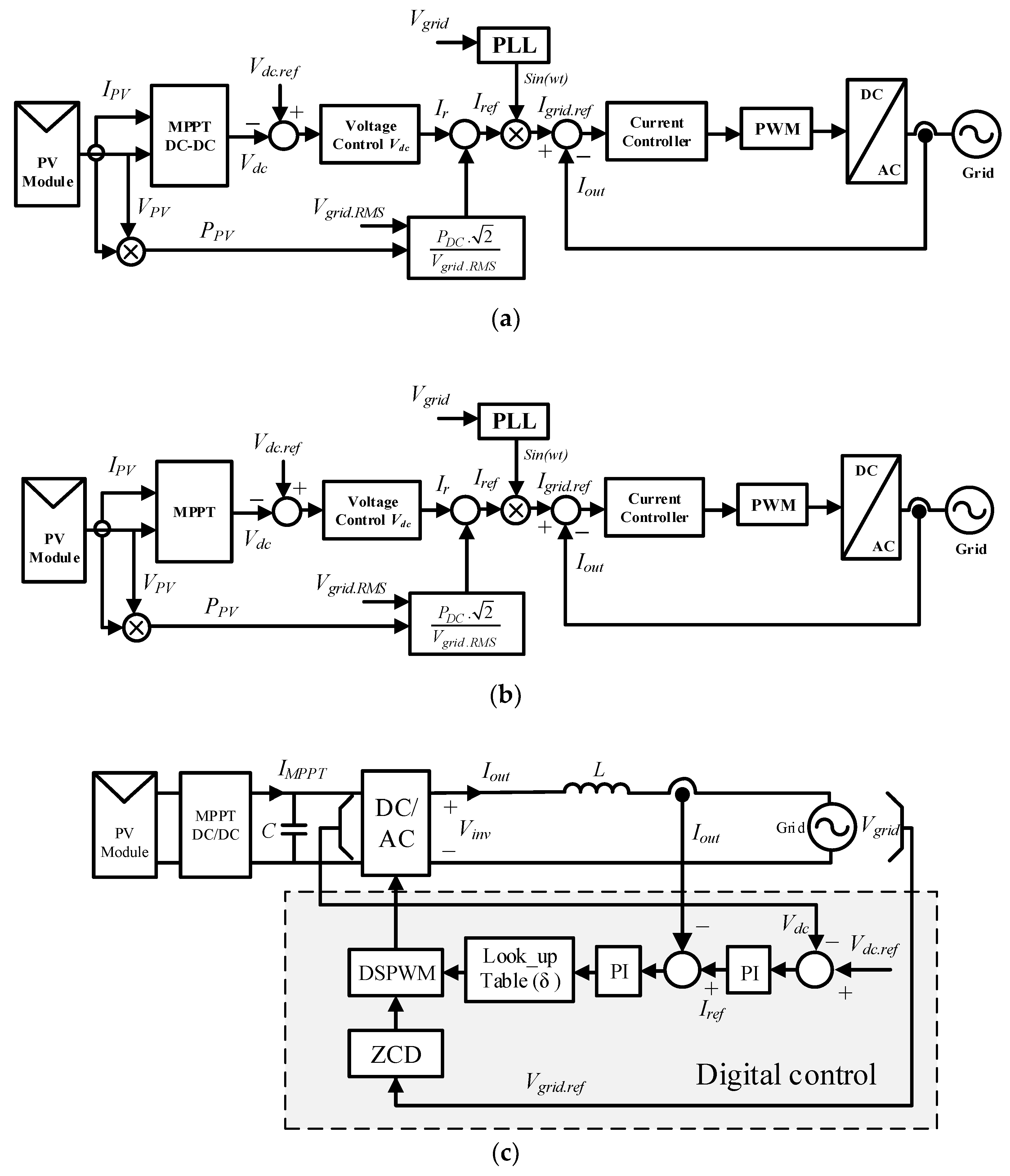
| Topologies | Advantage | Disadvantages | Figures |
|---|---|---|---|
| DC/DC converter based Single phase inverter |
|
| Figure 24a |
| Single phase inverter without DC/DC converter |
|
| Figure 24b |
| Single phase inverter with PCSP |
|
| Figure 24c |
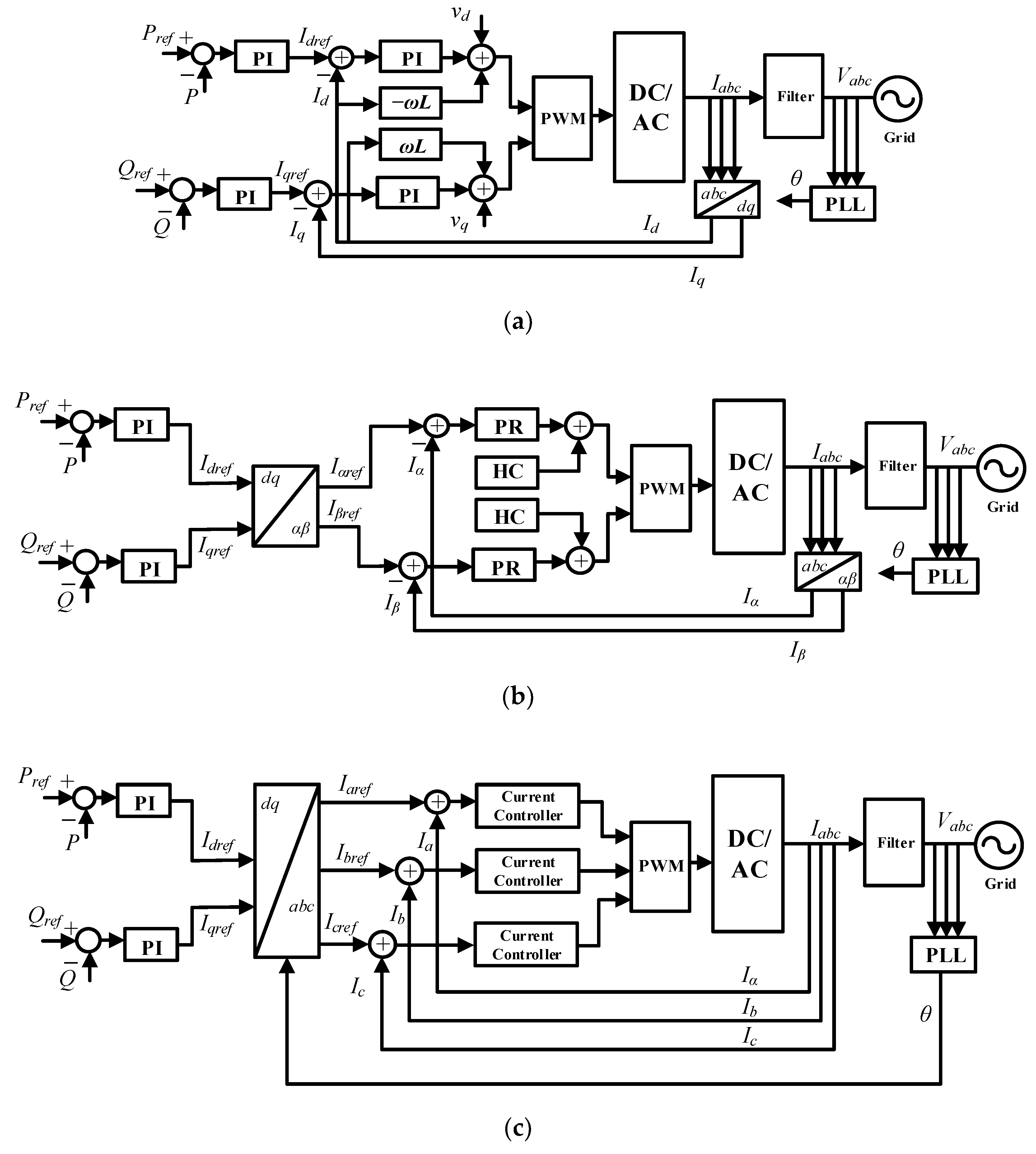
| Topologies | Control Equations | Advantage | Inconvenient | Figures | Controller Type |
|---|---|---|---|---|---|
| dqcontrol | or when ; or when |
|
| Figure 25a | PI |
| -control | or when ; or when |
|
| Figure 25b | PR |
| abc control |
| Figure 25c | PI | ||
|
| PR | |||
|
| Hysteresis | |||
|
| Dead-Beat |
© 2018 by the authors. Licensee MDPI, Basel, Switzerland. This article is an open access article distributed under the terms and conditions of the Creative Commons Attribution (CC BY) license (http://creativecommons.org/licenses/by/4.0/).
Share and Cite
Zeb, K.; Khan, I.; Uddin, W.; Khan, M.A.; Sathishkumar, P.; Busarello, T.D.C.; Ahmad, I.; Kim, H.J. A Review on Recent Advances and Future Trends of Transformerless Inverter Structures for Single-Phase Grid-Connected Photovoltaic Systems. Energies 2018, 11, 1968. https://doi.org/10.3390/en11081968
Zeb K, Khan I, Uddin W, Khan MA, Sathishkumar P, Busarello TDC, Ahmad I, Kim HJ. A Review on Recent Advances and Future Trends of Transformerless Inverter Structures for Single-Phase Grid-Connected Photovoltaic Systems. Energies. 2018; 11(8):1968. https://doi.org/10.3390/en11081968
Chicago/Turabian StyleZeb, Kamran, Imran Khan, Waqar Uddin, Muhammad Adil Khan, P. Sathishkumar, Tiago Davi Curi Busarello, Iftikhar Ahmad, and H. J. Kim. 2018. "A Review on Recent Advances and Future Trends of Transformerless Inverter Structures for Single-Phase Grid-Connected Photovoltaic Systems" Energies 11, no. 8: 1968. https://doi.org/10.3390/en11081968