Flow Structure and Heat Transfer of Jet Impingement on a Rib-Roughened Flat Plate
by
 ,
,
Abdulrahman H. Alenezi
1,* ,
,
Abdulrahman Almutairi
1, 
Hamad M. Alhajeri
1,
Abdulmajid Addali
2 and
Abdelaziz A. A. Gamil
3 1
Mechanical Power and Refrigeration Technology Department, College of Technological Studies, Shuwaikh Educational, P. O. Box 23167, Safat, Al-Asamah 13092, Kuwait
2
Advanced Centre for Technology, Tripoli, Libya
3
Department of Power and Propulsion, Cranfield University, Cranfield, Bedfordshire MK43 0AL, UK
*
Author to whom correspondence should be addressed.
Energies 2018, 11(6), 1550; https://doi.org/10.3390/en11061550
Submission received: 5 May 2018
/
Revised: 27 May 2018
/
Accepted: 10 June 2018
/
Published: 13 June 2018
(This article belongs to the Special Issue Fluid Flow and Heat Transfer)
Abstract
:The jet impingement technique is an effective method to achieve a high heat transfer rate and is widely used in industry. Enhancing the heat transfer rate even minimally will improve the performance of many engineering systems and applications. In this numerical study, the convective heat transfer process between orthogonal air jet impingement on a smooth, horizontal surface and a roughened uniformly heated flat plate is studied. The roughness element takes the form of a circular rib of square cross-section positioned at different radii around the stagnation point. At each location, the effect of the roughness element on heat transfer rate was simulated for six different heights and the optimum rib location and rib dimension determined. The average Nusselt number has been evaluated within and beyond the stagnation region to better quantify the heat transfer advantages of ribbed surfaces over smooth surfaces. The results showed both flow and heat transfer features vary significantly with rib dimension and location on the heated surface. This variation in the streamwise direction included both augmentation and decrease in heat transfer rate when compared to the baseline no-rib case. The enhancement in normalized averaged Nusselt number obtained by placing the rib at the most optimum radial location R/D = 2 was 15.6% compared to the baseline case. It was also found that the maximum average Nusselt number for each location was achieved when the rib height was close to the corresponding boundary layer thickness of the smooth surface at the same rib position.
1. Introduction
In the early 1960s, the jet impingement cooling technique was first introduced for internal cooling. It is a complex technique, but the most effective one when a high heat transfer rate is required. The complexity of impinging jet flow makes the heat transfer from/to the surface subjected to such flows difficult to resolve. However, a range of jet configurations and parameters have been investigated in terms of both heat transfer and fluid flow. The parameters which are known to influence the rate of heat transfer between the jet and the target surface includes Reynolds number, level of turbulence, jet-to-target distance, intermittency, nozzle geometry, target surface roughness, and jet temperature [1,2]. Kuraan et al. [3] performed a recent experimental study of a free water jet impinging a flat surface under the influence of jet-to-target distance of less than one. The effects of jet-to-target distance on stagnation point Nusselt number (Nu) and pressure were considered in this study under the influence of a wide range of Re between 4000 and 8053. New correlations of stagnation point Nu and pressure were reported in this study based on the author’s key findings. Zu et al. [4] presented results of a numerical study of the heat transfer behavior of a circular air jet impinging normally onto a flat plate with a nozzle to plate spacing ratios (H/D) of one to six. Their study used Fluent—a computational fluid dynamics (CFD) commercial package. Seven different turbulence models were implemented to evaluate modeling prediction capabilities by comparison with the benchmark experimental data. The Shear Stress Transport (SST k-ω) and Large Eddy Simulation (LES) models gave better accuracy in predicting both the heat transfer and fluid flow. With the high computational cost of LES, the SST k-ω turbulence model is an attractive and promising modeling option.
Heat and mass transfer as a function of surface roughness has been thoroughly considered by researchers such as Zhang, et al. [5] and Kim and Lee [6]. Basic studies using a single jet impinging on a roughened surface, with and without cross-flow, have been conducted by numerous investigators such as Beitelmal and Saad [7], Sharif and Ramirez [8], Xing and Weigand [9], Gabour and Lienhard [10], and Celik [11]. These investigations showed that a roughened surface could enhance the local Nu by up to 50% when compared to a smooth target surface, because of the turbulence induced by the surface roughness element. This enhancement due to surface roughness was investigated by many researchers employing different arrangements of jet impingement parameters [12,13,14,15,16,17,18]. More recent investigations [19,20] studied the effect of using novel jet impingement parameters such as solid volume fraction, Richardson number, and roughness element orientation on either local or average Nu number heat transfer rate between the roughened surface and impingement jet.
The literature to date agrees that the use of turbulence promoters (i.e., ribs) has a major impact on enhancing heat transfer rate [7,8,9,10,11,14,15]. However, most of these studies were conducted using turbulators with fixed dimensions and locations on the heated surface. This research employs uniform turbulence promoters with variable locations and dimensions to study the impact on the heat transfer rate between the working fluid and the heated surface.
2. Numerical Methodology
In all the cases simulated in this research paper, the jet flow had a velocity of 24.8 m/s. The air was assumed to be incompressible due to its low Mach number, and with the assumption of axisymmetric flow, the governing equations are:
where is the viscous dissipation heat source
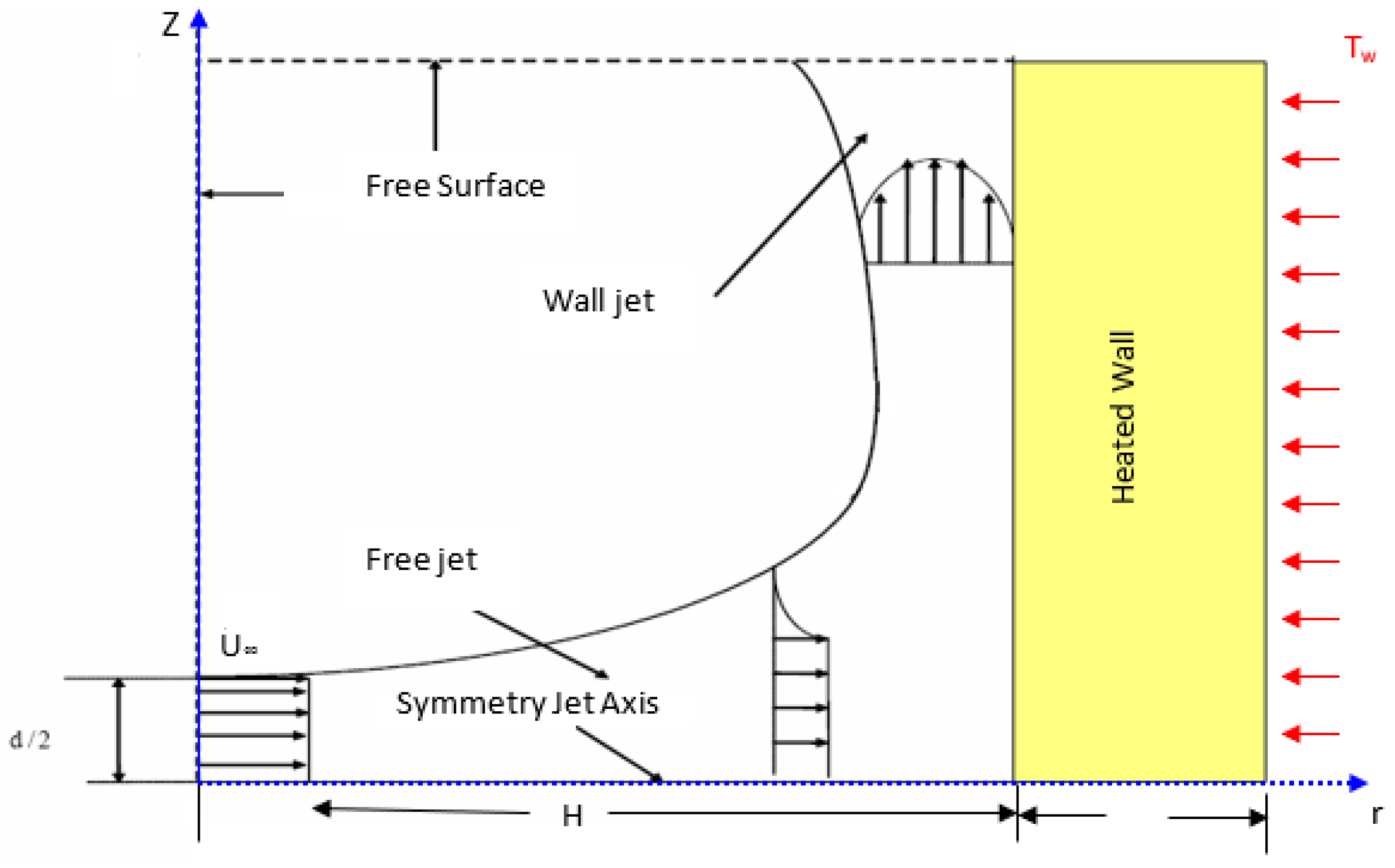
Here, , P, and T are the density, average pressure, and temperature, respectively. U and V are velocity components in the z and r directions, whereas are the fluctuating velocity components and temperature in the z and r directions. Finally is the heat capacity of air at constant pressure. All geometry and domain details are shown in Figure 1.
Flow can exist in three regimes: laminar, turbulent or in the transitional phase. Laminar, or streamline flow occurs at relatively low flow velocities and can be characterized as layers of fluid flowing in parallel with no disruption between them. Turbulent flow, however, occurs at a high Reynolds numbers with the presence of random fluctuations and disruptions. The flow regime can be specified by the value of Reynolds number () which is defined as the ratio of inertial and viscous forces. Based on the bulk jet exit velocity (U) and nozzle diameter (D), Reynolds number can be defined as:
where and are, respectively, the dynamic and kinematic viscosities of the fluid.
The Nusselt number, , is the ratio of convective to conductive heat transfer. If its value is close to unity, that means both convection and conduction have a similar magnitude and the flow will be almost stationary or laminar. However, if has a large value, it means more heat is convected than conducted, and the flow will be turbulent. can be defined as:
where k is the thermal conductivity of the fluid, and h is the convective heat transfer coefficient which is given by:
Usually is either the jet temperature () or the adiabatic wall temperature (, the latter can be obtained from the non-dimensional recovery factor:
factor =
The Nusselt number varies depending on the temperature chosen as the reference temperature . For low Reynolds numbers, the difference in the value of the Nusselt number won’t be noticeable. However, for large Reynolds numbers, the reference temperature must be appropriately chosen. How to choose the reference temperature has been explained by References [21,22].
2.1. Computational Domain, Boundary Conditions, and Grid Independence Check
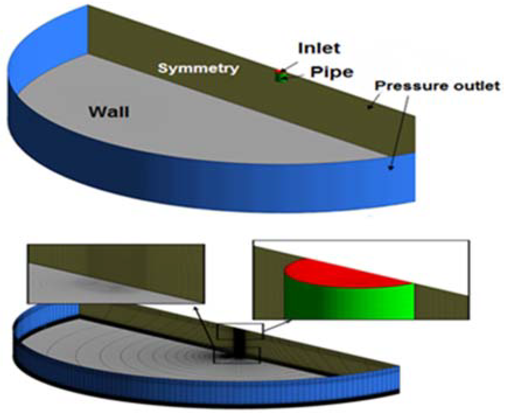
A schematic representation of circular jet impingement is shown in Figure 2, which is consistent with the experimental setup described by O’Donovan and Murray [23]. An orthogonal jet impinged on an isothermal flat plate is kept at a constant temperature of 60 °C, where the nozzle exit velocity was obtained from the jet exit Reynolds number, which was first set at = 10,000 and then at 20,000. Geometric dimensions were normalized relative to the nozzle hydraulic diameter (D = 13.5 mm), the normalized vertical distance between the flat plate (target), and the nozzle exit (jet) (H/D), and the normalized radius of the rib (R/D). The chosen value of H/D was six and the angle of impingement was 90° (orthogonal). The circular domain diameter (, which included the heated impingement surface, was 40D. The assumption of using an axisymmetric model in the simulation was to save computational time and cost.
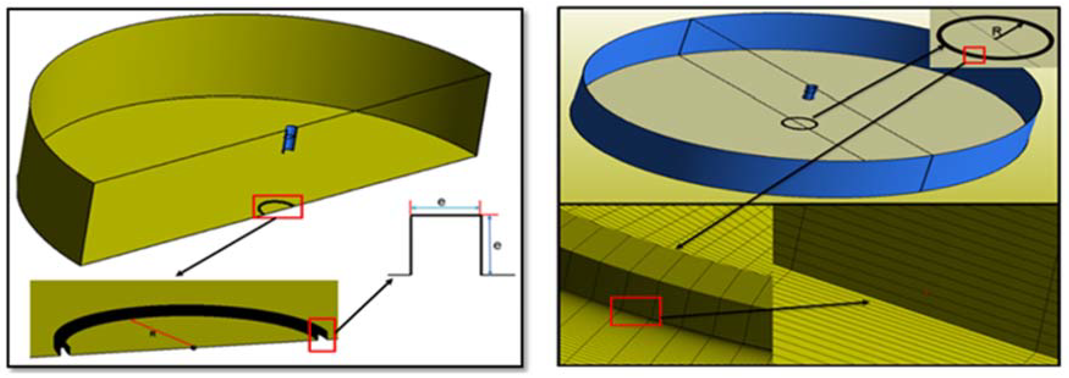
Figure 3 illustrates the geometry and meshing strategy used in the case of the roughened flat plate. It is well known from the literature that the near wall regions have a large impact on the solution variables and momentum, and thus extra care was taken with near-wall meshing in this model to get accurate results. Hexahedral elements were used by block-structured grids using spatial discretization of the domain. A very fine mesh was applied in the direction normal to the heated surface as well as the roughness elements to ensure proper functionality of the turbulence model, especially low Reynolds numbers which required a dimensionless distance between the wall and the first node of less than unity. The growth rate of the cell near the heated surface where all heat transfer takes place was no greater than 1.2 in the direction normal to the heated surface. O-grid strategy was applied within and near the round nozzle to ensure high cell orthogonality. The total grid size was approximately one million for the whole computational domain.
2.2. Grid Independence and Turbulence Model Validation
The mesh strategy used in this simulation was intended to resolve the wall boundary layer accurately. A fine structured mesh was adopted and then refined near the wall where pressure, velocity and turbulence gradients occur, to achieve a stable numerical solution (see Figure 3). The value was maintained at less than unity near the wall using at least ten nodes within the viscous sub-layer as recommended by Reference [24]. Here y+ is a dimensionless quantity related to the distance between the wall and the first mesh node above it. It is important that the first cell should be fine enough to avoid positioning it in the buffer layer. The is a function of both free stream properties and velocity ( .
A non-uniform finite volume mesh with collocated variable locations was used for the computations, where the mesh density was carefully scaled to investigate the sensitivity of the predicted results to the number of grid nodes. A rectangular mesh gathered toward both top and bottom walls, with a bias factor of 70, was used in the z-direction. Finer computational meshes were adopted near the heated surface and the nozzle to obtain accurate values for velocity and thermal boundary layer. The grid size modified in this study was approximately one million cells based on a systematic grid independence study. The turbulence models including Re-Normalisation Group (RNG) k-epsilon, used in this study gave good results when using a value less than five in the boundary layer region, and employing 5 to 30 nodes within this region [24].
3. Results and Discussion
3.1. Simulation Characteristics
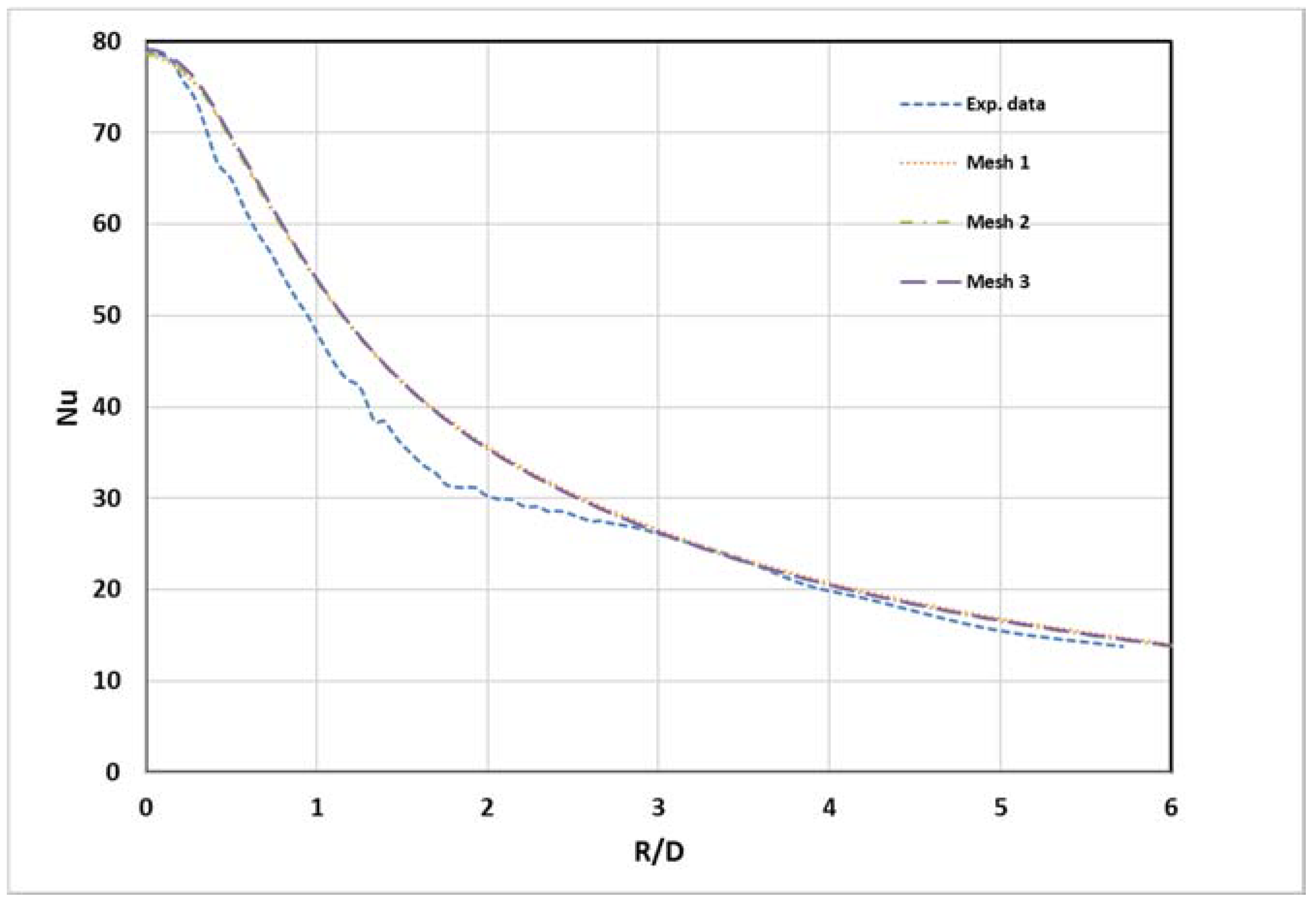
To validate the results, comparisons were made between numerical data obtained in this research and the experimental data of O’Donovan and Murray [23]. A grid dependence study was then conducted to verify the independence of the numerical solution on mesh size. Table 1 below shows the three mesh sizes adopted in this research.
Figure 4 compares the simulated local values for the three mesh sizes with the experimental results along the normalized radial distance. The RNG k-epsilon turbulence model was used. The figure shows that both numerical and experimental data values were close for all grid sizes. Therefore, mesh 2 was adopted for the numerical calculations.
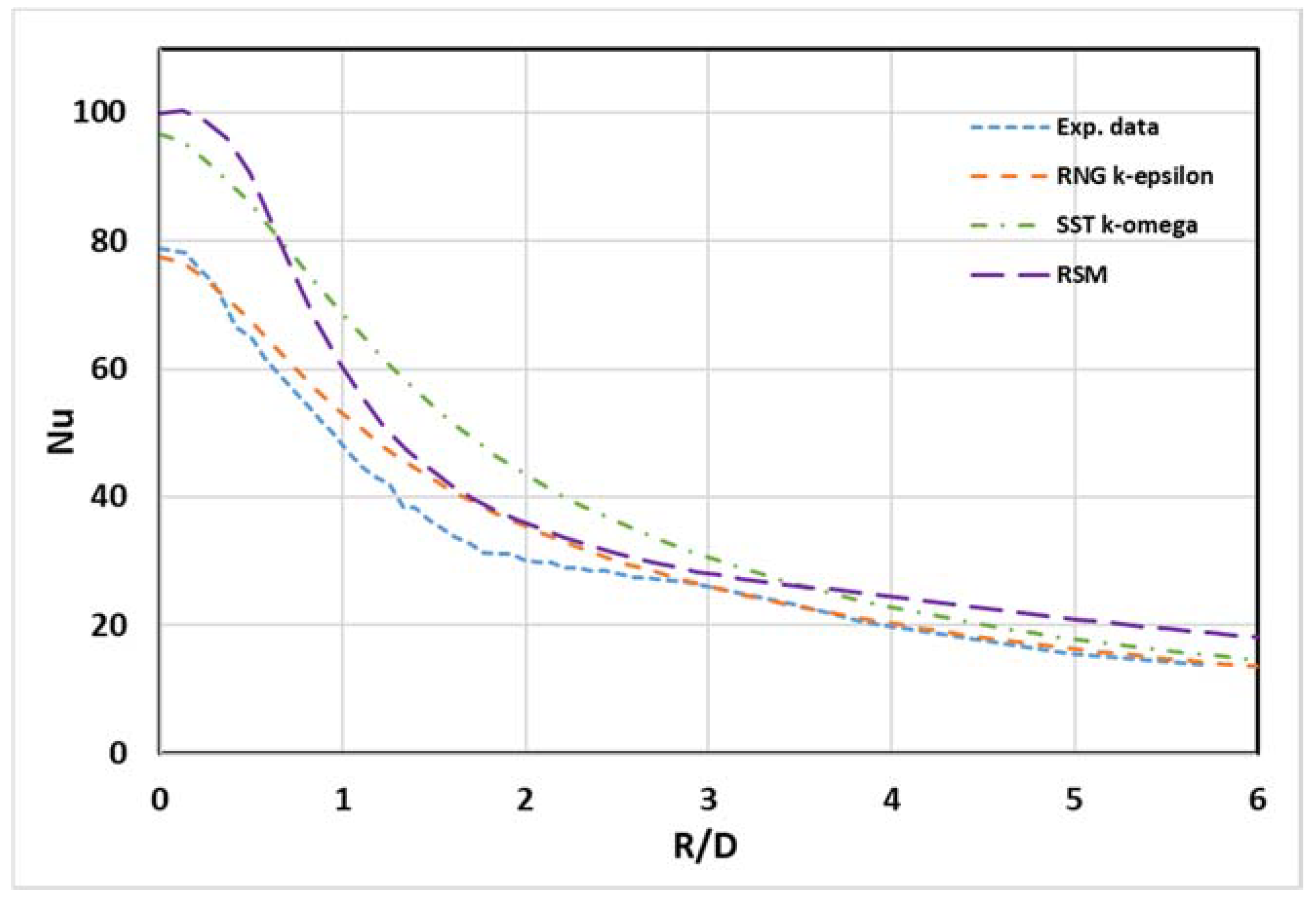
The distribution of the local Nusselt number along the pre-heated impingement surface was compared with the experimental data of O’Donovan and Murray [23] for H/D = 6 and α = 90° using different turbulence models (see Figure 5). The RNG k-epsilon turbulence model showed better overall agreement with the experimental data and succeeded in predicting the local stagnation point Nusselt number () with an error of only about 1.7%. However, both SST k-ω and RSM models overestimated with errors of 18% and 21%, respectively. Moving in the radial direction, the RNG k-epsilon turbulence model gives, overall, a more accurate prediction of local values. Unfortunately, none of the models discerned the slight trough in the experimental results at R/D ~2, which gave rise to the small maximum at R/D ~3. Based on this evaluation, the RNG k-epsilon turbulence model was selected to be used for this parametric study.
3.2. Aerodynamical Results
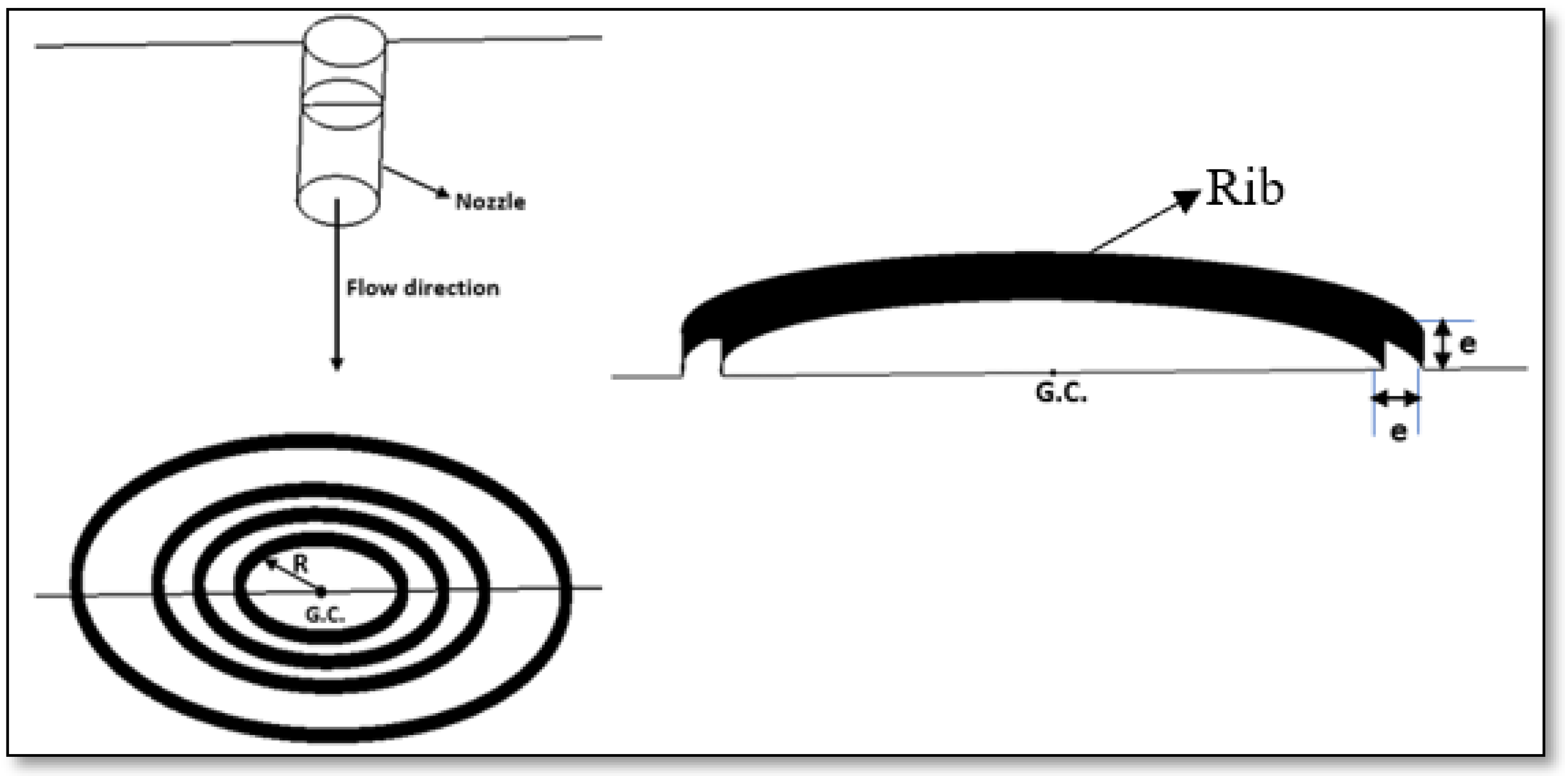
The following sections report results for the higher flow velocity, = 20,000, jet-to-target distance (H/D) = 6, and jet angle α = 90°. The study included simulating the effect of rib location and rib height on the average Nusselt number (). The rib was tested with four different values of radial distance: R/D = 1, 1.5, 2, and 3, where D was the jet hydraulic diameter, and for each location it was tested for six different rib heights (e) between 0.25 mm and 1.5 mm in increments of 0.25 mm to ascertain the optimum height for each location. This range of rib locations should extend from within to outside the stagnation region. Figure 6 shows the geometric details of the rib cross-section and all four rib locations (R) simulated in this research paper. These radial locations tested cover both the stagnation and wall jet regions.
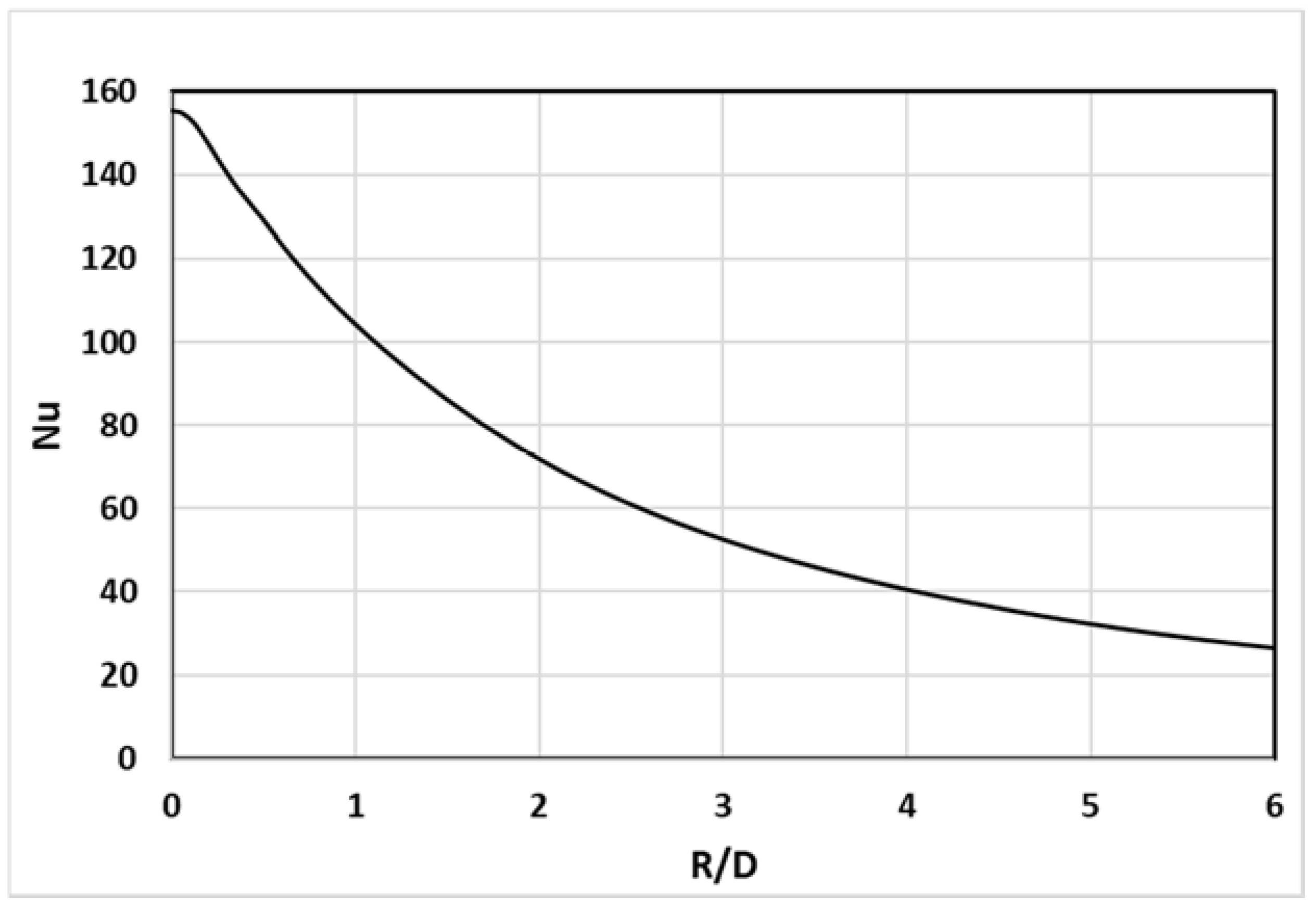
First, it was required to determine the effect of the new value of on heat transfer for the smooth flat plate configuration. Figure 7 shows the local values with the radial distance on the heated surface. Overall, the local values are higher for the higher Re, with the maximum value, as expected, at the stagnation point (R/D = 0). As can be seen in the figure, a noticeable decrease in values occurs as the flow travels downstream losing about 53% of its maximum value at a radial distance R/D = 2.5.
The value of the velocity boundary layer thickness (δ) has been estimated in the literature [25] as one-tenth of the hydraulic diameter (0.1D) for the stagnation zone. While for the wall jet region it has been estimated at 95% of that for the free stream velocity at each radial location, Table 2 demonstrates values of velocity boundary layer thickness at each tested radial location for the unobstructed flat surface.
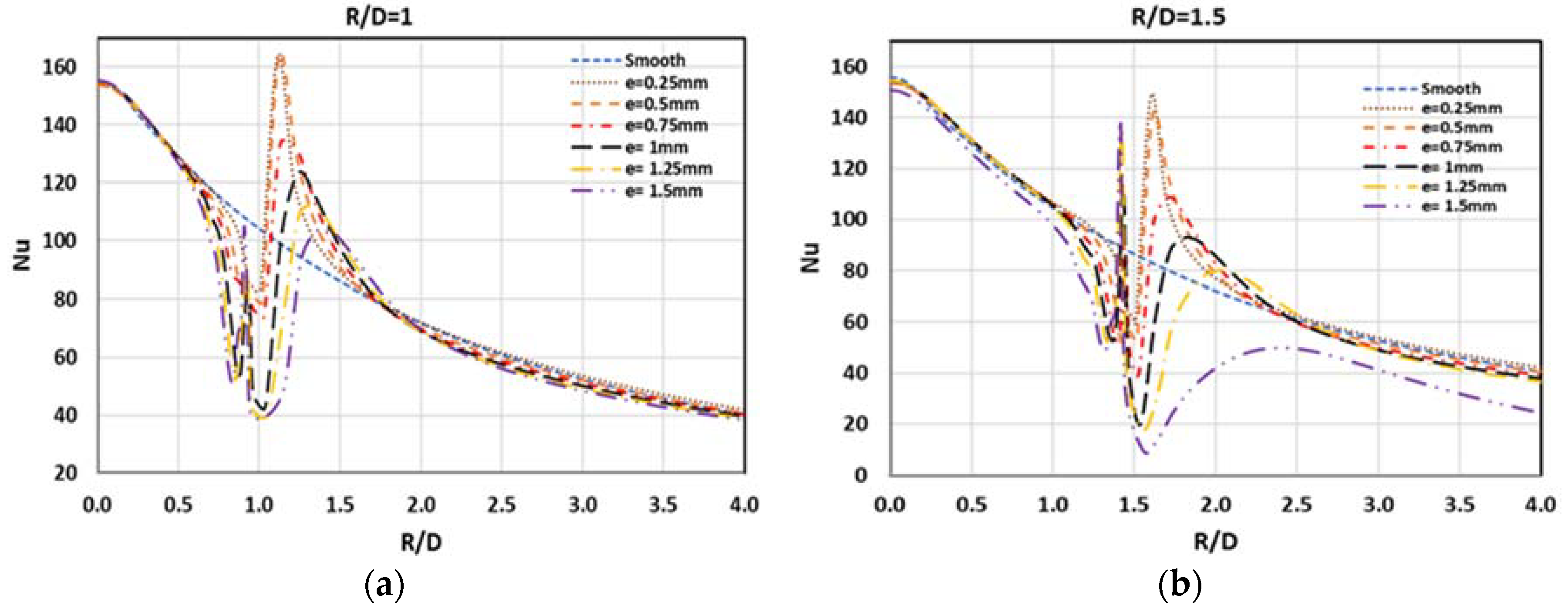
The rib was placed at radial distances R/D = 1 and 1.5 and positioned within or close to the stagnation region [26]. As mentioned above, the rib height (e) was varied to find the optimum rib geometry that gave maximum average . Figure 8 shows the effect of rib height on the local distribution of for a circular jet impinging normally on a flat plate. As shown in the figure, the local value of directly behind the rib is increased because of rib induced flow separation and re-attachment. In very simple terms, it disturbs the stagnation layer which acts to insulate the surface. Depending on geometry and circumstances, the ribs may also increase heat transfer by increasing the effective area of the surface [27]. It can be seen from the figure that the higher the rib (greater e), the lower the local value due to lower flow turbulence intensity as the flow travels a longer distance after passing the rib before re-attaching. The re-attachment point is where the flow hits the heated surface after passing the rib, the velocity with which the flow hits the surface at this point is known as the “arrival velocity”.
For rib heights of 0.25, 0.50, and 0.75 mm, enhancement of heat transfer rate was achieved. Where e ≥ 1 mm, all rib heights caused a subsidiary peak in the local immediately in front of the rib due to the flow recirculation that occurred before the protrusion. However, the increase in the drag resulting from the presence of ribs with e ≥ 1 mm caused the impinging jet to decelerate and disperse more rapidly, such that further from the stagnation point the value of decreased, as shown in the figure.
For the special case where R/D = 1.5 and e = 1.5 mm, the stagnation Nusselt number starts to be noticeably affected by the rib height showing a significantly lower value than for the baseline case. This is due to the lack of re-attachment between the flow and the heated target surface, which was not the case for R/D = 1, see Figure 9.
Gau, et al. [28] reported this phenomenon for a 2-D air slot jet impingement on a flat rectangular surface with straight ribs of different heights attached perpendicular to the flow. They explained that the shear layer, while separated from the surface, experiences turbulence effects which enhance momentum and mass (heat) transfer so that its re-attachment to the surface behind the rib results in an increase in heat transfer. After this impingement, the turbulent free shear layer reattaches itself to the surface, and a new boundary layer develops. Thus, placing ribs normal to the flow of the wall jet is an effective means for enhancing total heat transfer rate to/from the wall by disrupting the rather rapid decrease in convective heat transferred to/from the wall.
The formation of a boundary layer begins in the stagnation region with a thickness of no more than one-tenth of the jet hydraulic diameter [26]. The locations R/D = 2 and 3 represent the beginning of the wall jet region [27] where the flow starts to exchange momentum with the wall. The wall jet boundary layer thickness is influenced by both flow velocity gradients with respect to the no-slip wall and with respect to the stationary flow above the jet. The wall shearing layer thickness increases as the flow move downstream, while its average velocity decreases due to momentum exchange with the wall. Depending on the velocity gradients, rib location could have a different impact on the flow physics and heat transfer rate.
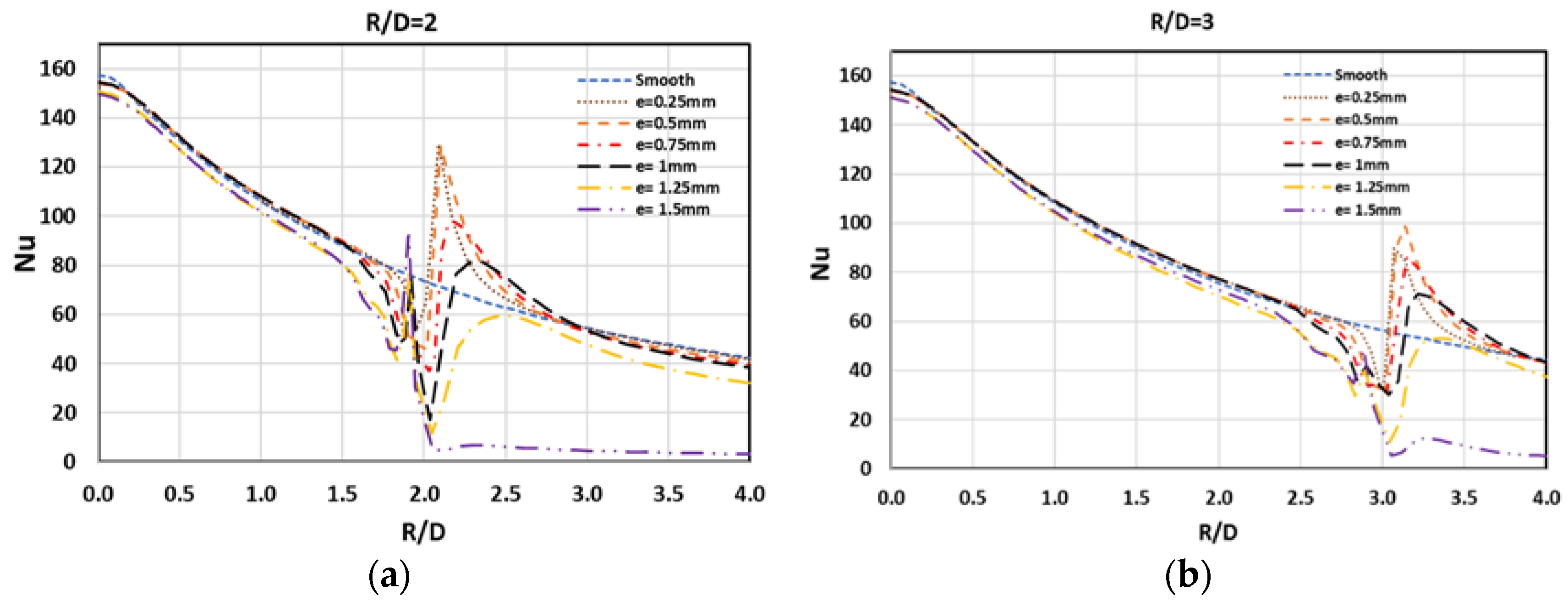
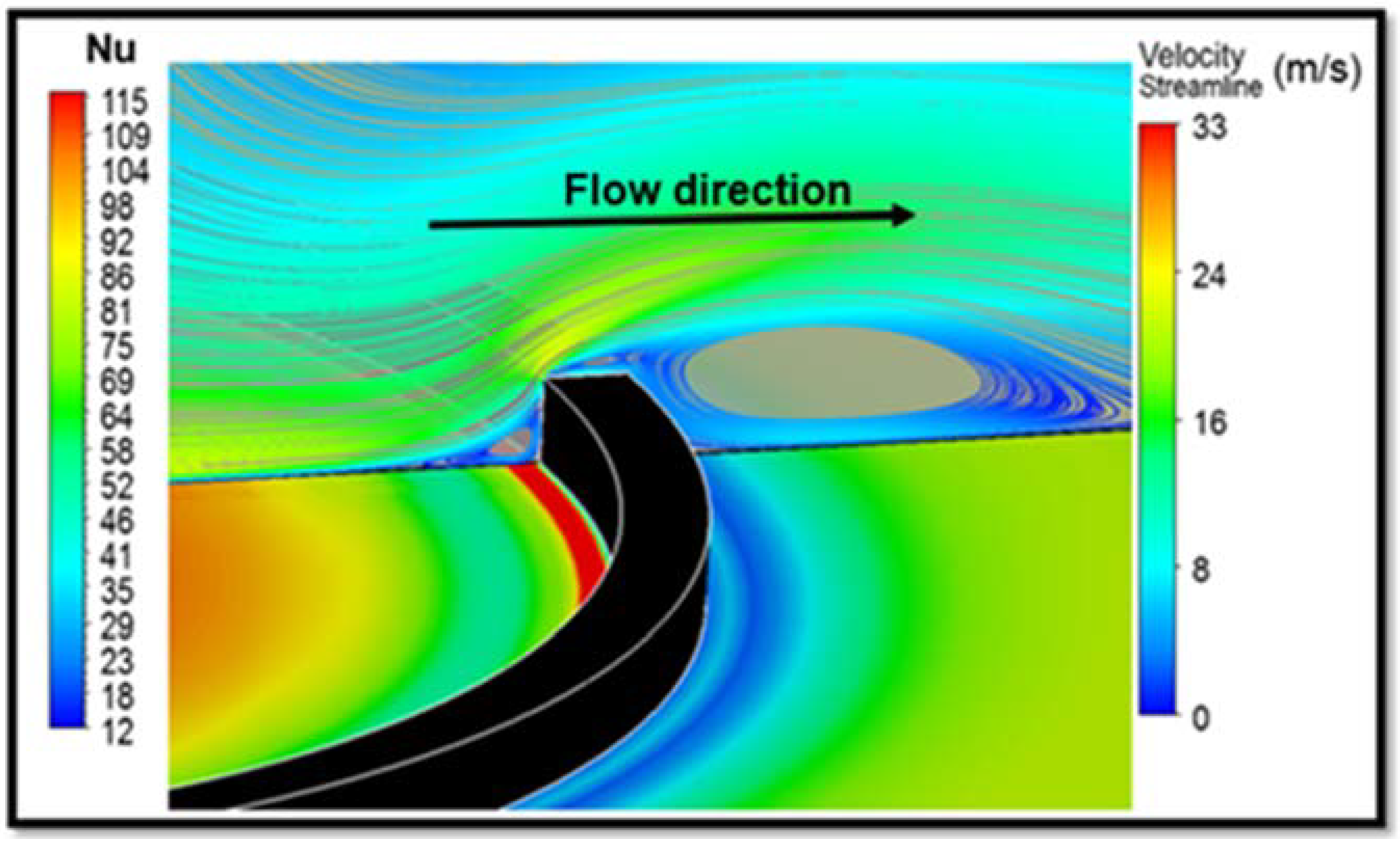
By comparison with the baseline case, placing the circular rib at R/D = 2 and 3, improves the local significantly (see Figure 10). This enhancement is a result of the high turbulence level induced by the flow recirculation before and after the rib. As rib height increases, the distance between the heated wall and the upper edge of the rib (where flow separation occurs) also increases, causing the flow to travel a greater distance before it re-attaches to the wall (see Figure 11). The re-attachment point shifts downstream (to the right on Figure 10). Unlike the two radial locations previously discussed, the average enhancement lasts till rib height, e = 1.00 mm. For e ≥ 1 mm, another peak occurs just before the rib, due to flow recirculation in front of the rib which enhances the heat transfer rate in this region.
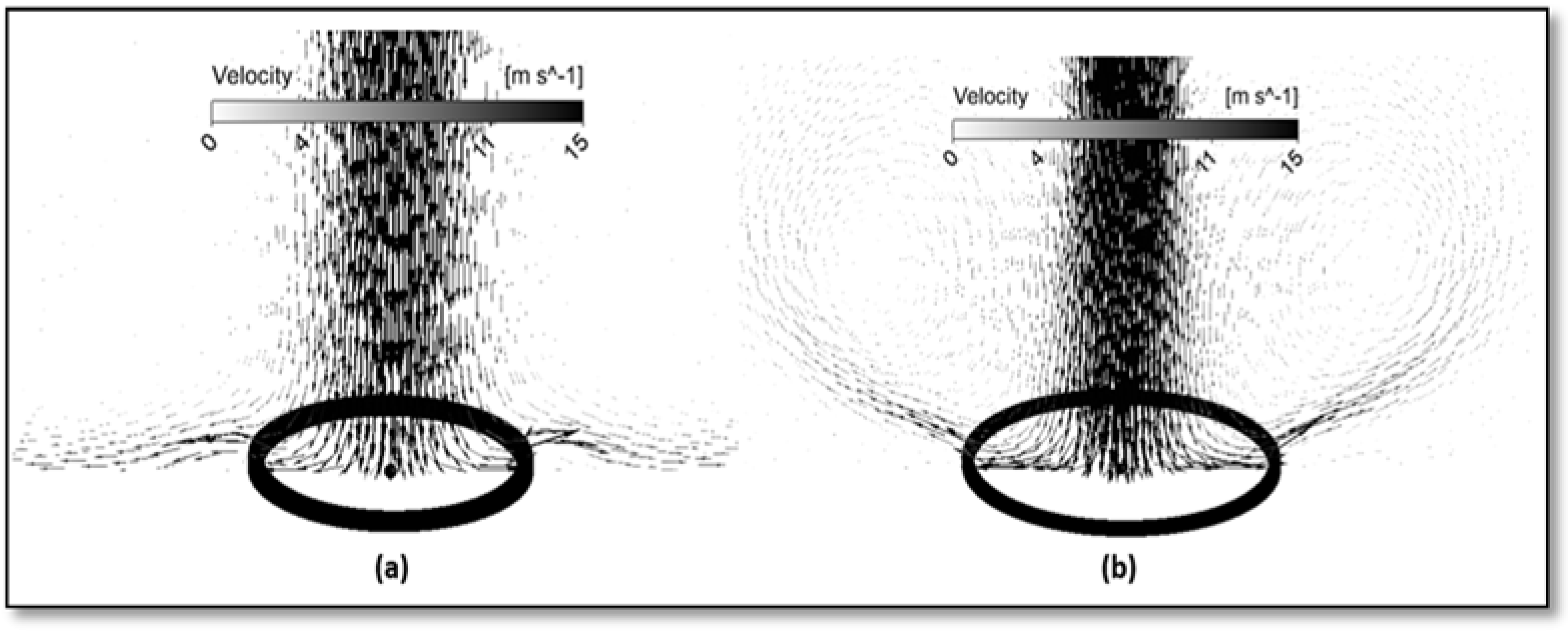
Figure 12 presents velocity contours for three rib heights at R/D = 2 and 3, and shows that flow separation takes place in front of the rib resulting in a small separation region followed by a larger after-rib recirculation vortex. It also shows that the highest flow velocity is located above the top of the protrusion, while the lowest velocity is found at the bottom and around the protrusions. It can be seen that the flow with higher velocity, at R/D = 2 and 3, exists predominantly for protrusions with lower heights.
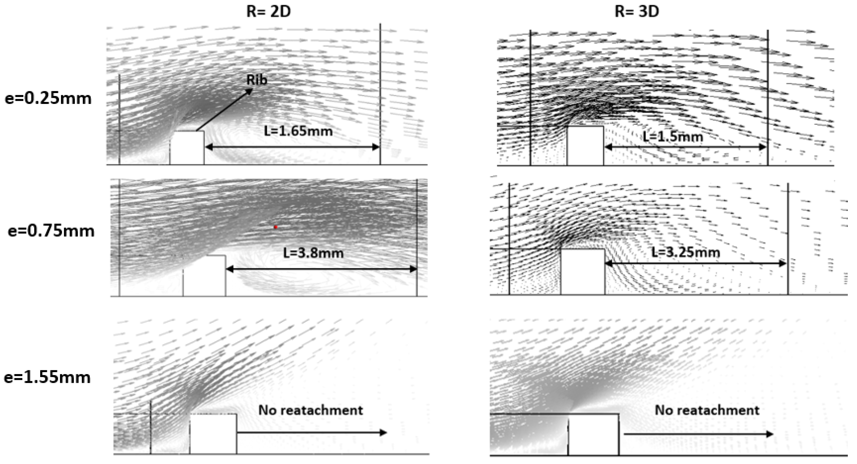
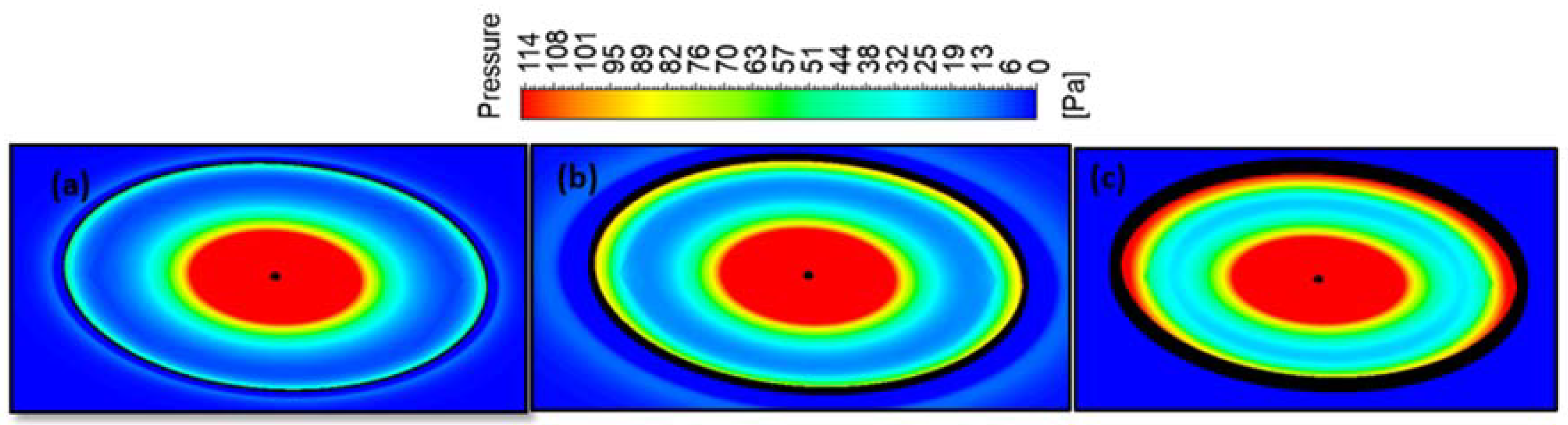
A protrusion usually exerts drag on the flow, causing a pressure build up and lower velocity, as shown in Figure 13, which shows that the higher the rib, the more the pressure build up. After the flow passes the protrusion a low-pressure region will occur behind the protrusion. Flow recirculation and higher turbulence will then occur in this low-pressure region which enhances the heat transfer rate. However, depending on the height and shape of the protrusion, this low-pressure region could be large enough to have a negative effect on heat transfer rate by preventing the main jet flow proceeding on its regular path. Figure 12 demonstrates this fact as it shows that the higher the rib, the larger the low-pressure region, and the longer distance the flow travels before it re-attaches to the heated surface.
The re-attachment length (L), which represents the length of the low-pressure region, increases as the rib height increases, this is true until above a certain height, the flow does not re-impinge on the heated surface and travels upward instead. Here, at e = 1.50 mm, the flow failed to reattach.
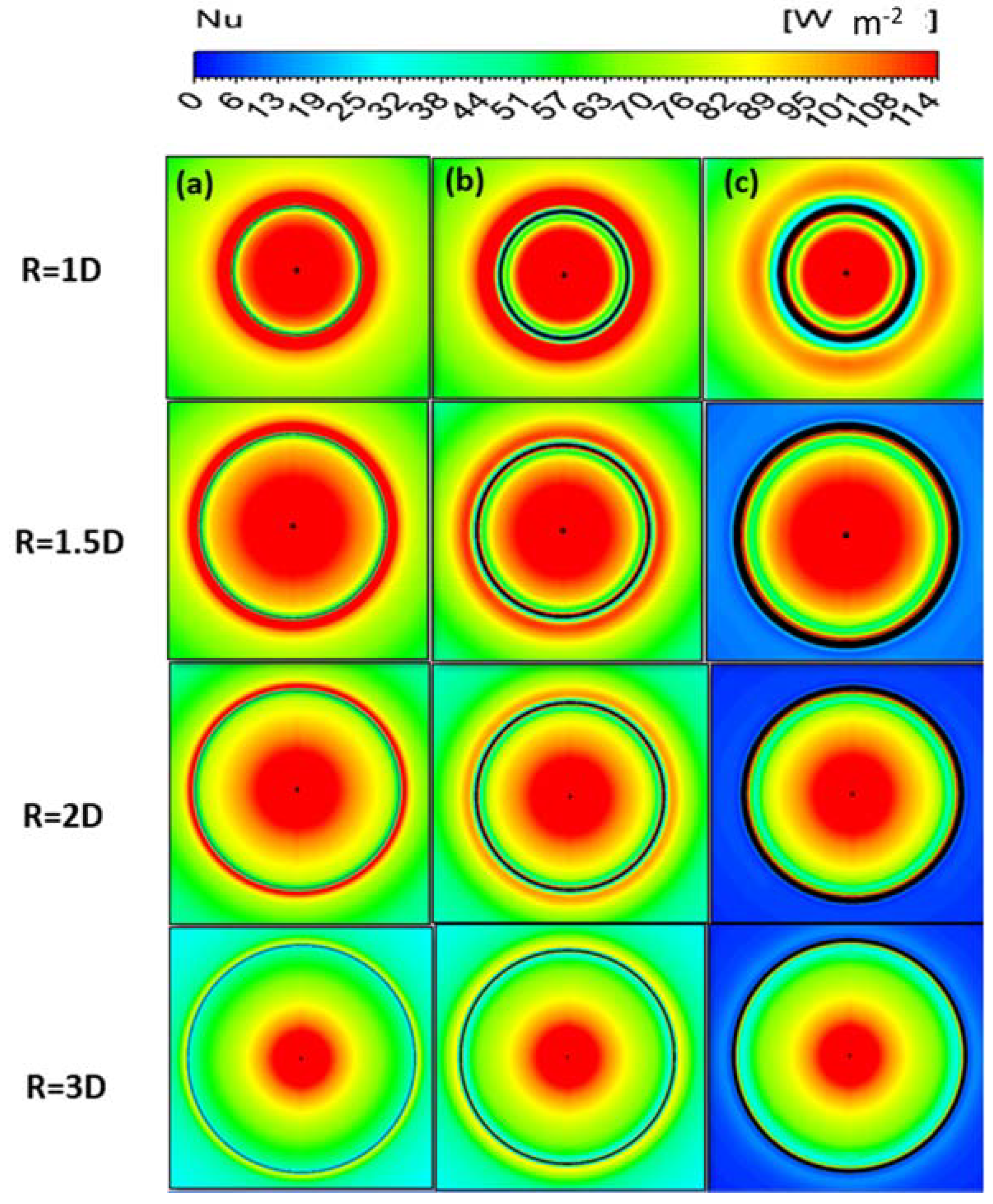
Figure 14 shows contours of local distributions for three rib heights for the four radial locations the circular rib is represented by the black circle. The low-pressure region (wake), where there was flow recirculation, is shown by the blue area behind the rib. As can be seen from the figure, as the rib height increased, the extent of the low-pressure region behind the also rib increased. This process continued as the rib height increased, until at a rib height of 1.50 mm, the flow did not re-attach, but travelled upward away from the heated surface. This happened only for locations between R/D = 1.5 to 3, because R/D = 1 was within the stagnation region.
3.3. Average Characteristics
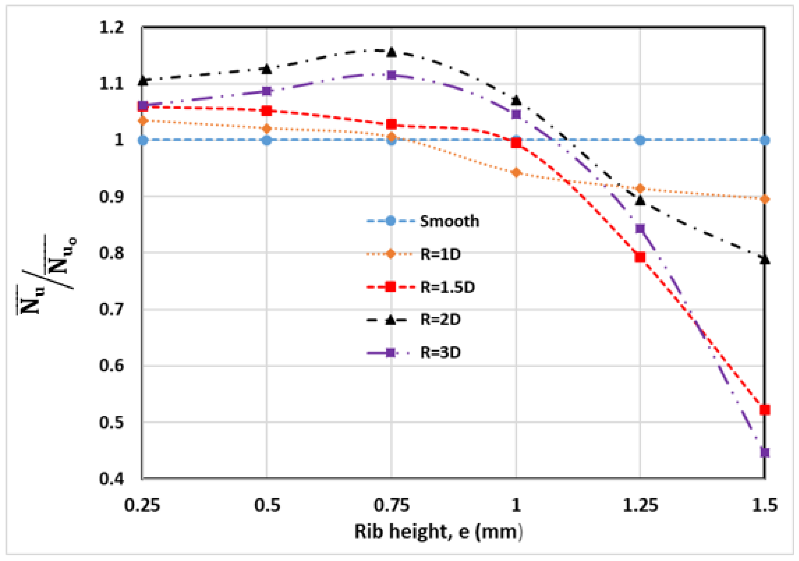
Figure 15 shows the effect of rib height on the average Nu of the heated surface, by presenting the average () normalized to the average of the baseline () for all rib radial locations. The average was obtained by numerically integrating the local between 0 ≤ R/D ≤ 4, in the downstream direction using Equation (10). It should be noted, for completeness sake, that the local heat transfer was, in fact, slightly affected at distances further downstream than R/D ≥ 4 for rib heights 0.25 ≤ e ≤ 0.75 mm, as was previously shown in Figure 8. The optimal rib height, at both R/D = 1 and R/D = 1.5, was e = 0.25 mm, which gave an increase in relative () of 3.5% and 6%, respectively, compared to the baseline (no rib) case. Unlike the two locations at R/D = 1.0 and 1.5, discussed above, placing the rib at R/D = 2 enhanced heat transfer even for a rib of height, e = 1.00 mm. For R/D = 2, ribs in the range 0.25 ≤ e ≤ 1.00 mm, the enhancements with respect to the baseline case were 10.5%, 15.6%, 12.7%, and 10.7%, respectively. Thus, there was a greater increase in heat transfer rate with the rib at this radial location compared to previous locations. For R/D = 3, a maximum enhancement in the average of about 11.5% was achieved by introducing a rib with height 0.75 mm. Rib heights of 0.25 mm, 0.50 mm, and 1.00 mm gave enhancements of the average Nusselt number of 6.2%, 8.7%, and 4.5%, respectively. A drop in heat transfer was noticeable as rib height increased above e ≥ 1.00 mm. The use of inappropriate rib height, of e = 1.50 mm say, could lead to a loss of heat transfer of over 55% compared to the baseline case.
3.4. Comparison of Results
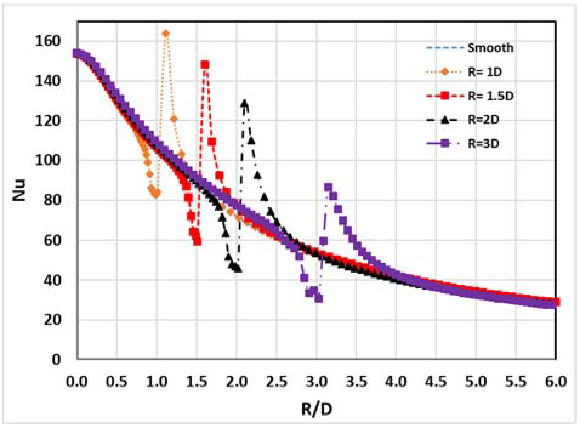
This research paper has presented the results of a simulation exercise on the effect of rib location and height on normalized , averaged over a surface area. Figure 16 shows the effect on the local Nusselt number for ribs located at different radii from the center of the jet. Here the range of R/D was 1.0, 1.5, 2, and 3, and most of the heat transfer takes place in this region. For each rib location, the local distribution determined the optimal rib height. As the radial distance of the rib from the stagnation point increased, and as R/D increased, the local maximum associated with the presence of a rib decreased. This phenomenon is explained by the combined effects of the decrease in turbulent energy of the fluid as it moves away from the stagnation point and the rapid decrease in the velocity of the wall jet with radial distance from the impingement point.
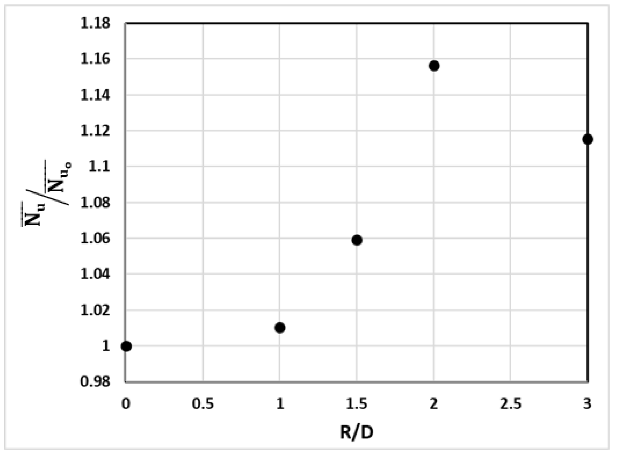
Figure 17 shows the normalized average Nusselt number for a circular rib on the target surface. The Nusselt number was normalized by dividing by the value for the averaged Nu over 0 ≤ R/D ≤ 4 when no rib was present. The optimum rib height at each rib location was shown in this figure to determine the maximum enhancement in heat transfer between all rib locations. Clearly the most effective location for the rib was at R/D = 2 for which = 1.156. For R/D ≥ 2, the averaged Nusselt number decreased as r increased. It is argued that maximum enhancement of the heat transfer rate was obtained when the rib was installed at a location close to the boundary between the stagnation region and the wall jet region, at R/D = 2.
Table 3 summarizes the main results reported in this research paper.
4. Conclusions
Numerical analysis of a convective heat transfer process was conducted on the orthogonal air jet impingement on a smooth, horizontal surface, and a roughened uniformly heated flat plate. The commercial software ANSYS 17.0 was used for modelling and analyzing of both proposed cases. The continuous circular rib with the square cross-section is used as a roughness element, while the tested surface area covers the range of 0 ≤ R/D ≤ 4. The circular roughness element was centered on the geometric center and tested for four different radii (R/D = 1, 1.5, 2, and 3) and six different heights (e) between 0.25 mm and 1.50 mm with an increment of 0.25 mm. In general, the rib height that matches the velocity boundary layer thickness at the rib location seems to be the most effective height for maximizing heat transfer rate. However, too high a rib gave a lower heat transfer rate than the no-rib case. It was also found that placing the rib, regardless of its height, in the stagnation region was ineffective when seeking to enhance heat transfer. The most effective rib location was at R/D = 2 which, based on the literature, is the beginning of the wall jet region. The results showed that when using the optimum rib height and location, a maximum heat transfer enhancement of 15.6% was achieved. The range of heat transfer enhancement for the rib at R/D = 2 was between 10.7% and 15.6% for rib heights e ≤ 1.00 mm.
Author Contributions
A.H.A. conceived the study, built the numerical models, performed the numerical solution and wrote the paper; H.M.A. helped performing the numerical solution, improved the simulations accuracy and manuscript review, A.A. (Abdulrahman Almutairi) contributed with conception of the work, data interpretation and revision of the manuscript; A.A. (Abdulmajid Addali) participated in the elaboration of the manuscript; A.A.A.G. helped analysing the numerical results. All authors read, edited and approved the manuscript.
Acknowledgments
The authors wish to express their sincere thanks to the Exergy Engineering Solutions (EES) in the state of Kuwait for its valuable support and assistance to the current work.
Conflicts of Interest
The authors declare no conflict of interest.
Nomenclature
| Symbol | Description | Units |
| Re | Jet Reynolds number, ρUD/µ | m3/s |
| Cp | Heat capacity | J/kg·K |
| h | Convective heat transfer coefficient | W/m2K |
| Average heat transfer coefficient | W/m2K | |
| D | Hydraulic diameter | m |
| R | Rib radial location | m |
| Nu | Nusselt number, hD/k | - |
| Nustag | Stagnation Nusselt number | - |
| Average Nusselt number, | - | |
| Baseline case average Nusselt number | - | |
| qw | Wall heat flux | W/m2 |
| Tref | Reference temperature | °C |
| Taw | Adiabatic wall temperature | °C |
| Tw | Wall temperature | °C |
| Tj | Jet temperature | °C |
| Uj | Jet velocity | m/s |
| y+ | Near-wall distance | m |
| ν | Kinematic viscosity | m2/s |
| u∞ | Free stream velocity | m/s |
| δ | boundary layer thickness | mm |
| Dd | Domain diameter | m |
| P | Mean pressure | Pa |
| U, V, W | Streamwise, vertical and spanwise components of velocity | m/s |
| U′, V′, W′ | Streamwise, vertical and spanwise components of fluctuating velocity | m/s |
| T | Mean temperature | °C |
| T′ | Fluctuating temperature | °C |
References
- Jambunathan, K.; Lai, E.; Moss, M.A.; Button, B.L. A review of heat-transfer data for single circular jet impingement. Int. J. Heat Fluid Flow 1992, 13, 106–115. [Google Scholar] [CrossRef]
- Almutairi, A. Computation of Conjugate Heat Transfer in Impinging Flows. Master’s Thesis, University of Manchester, Manchester, UK, September 2010. [Google Scholar]
- Kuraan, A.M.; Moldovan, S.I.; Choo, K. Heat transfer and hydrodynamics of free water jet impingement at low nozzle-to-plate spacings. Int. J. Heat Mass Transf. 2017, 108, 2211–2216. [Google Scholar] [CrossRef]
- Zu, Y.Q.; Yan, Y.Y.; Maltson, J. Numerical Study on Stagnation Point Heat Transfer by Jet Impingement in a Confined Narrow Gap. J. Heat Transf. 2009, 131, 094504. [Google Scholar] [CrossRef]
- Zhang, D.; Qu, H.; Lan, J.; Chen, J.; Xie, Y. Flow and heat transfer characteristics of single jet impinging on protrusioned surface. Int. J. Heat Mass Transf. 2013, 58, 18–28. [Google Scholar] [CrossRef]
- Kim, W.S.; Lee, S.Y. Behavior of a water drop impinging on heated porous surfaces. Exp. Therm. Fluid Sci. 2014, 55, 62–70. [Google Scholar] [CrossRef]
- Beitelmal, A.H.; Saad, M.A. Effects of surface roughness on the average heat transfer of an impinging air jet. Int. Commun. Heat Mass Transf. 2000, 27, 1–12. [Google Scholar] [CrossRef]
- Sharif, M.A.R.; Ramirez, N.M. Surface roughness effects on the heat transfer due to turbulent round jet impingement on convex hemispherical surfaces. Appl. Therm. Eng. 2013, 51, 1026–1037. [Google Scholar] [CrossRef]
- Xing, Y.; Weigand, B. Experimental investigation of impingement heat transfer on a flat and dimpled plate with different crossflow schemes. Int. J. Heat Mass Transf. 2010, 53, 3874–3886. [Google Scholar] [CrossRef]
- Gabour, L.A.; Lienhard, J.H. Wall Roughness Effects on Stagnation-Point Heat Transfer Beneath an Impinging Liquid Jet. J. Heat Transf. 1994, 116, 81–87. [Google Scholar] [CrossRef]
- Celik, N. Effects of the surface roughness on heat transfer of perpendicularly impinging co-axial jet. Heat Mass Transf. 2011, 47, 1209–1217. [Google Scholar] [CrossRef]
- Kanokjaruvijit, K.; Martinez-Botas, R.F. Jet impingement on a dimpled surface with different crossflow schemes. Int. J. Heat Mass Transf. 2005, 48, 161–170. [Google Scholar] [CrossRef]
- El-Gabry, L.A.; Kaminski, D.A. Experimental Investigation of Local Heat Transfer Distribution on Smooth and Roughened Surfaces under an Array of Angled Impinging Jets. J. Turbomach. 2005, 127, 532–544. [Google Scholar] [CrossRef]
- Spring, S.; Xing, Y.; Weigand, B. An Experimental and Numerical Study of Heat Transfer from Arrays of Impinging Jets with Surface Ribs. J. Heat Transf. 2012, 134, 082201. [Google Scholar] [CrossRef]
- Caliskan, S. Flow and heat transfer characteristics of transverse perforated ribs under impingement jets. Int. J. Heat Mass Transf. 2013, 66, 244–260. [Google Scholar] [CrossRef]
- Wan, C.; Rao, Y.; Chen, P. Numerical predictions of jet impingement heat transfer on square pin-fin roughened plates. Appl. Therm. Eng. 2015, 80, 301–309. [Google Scholar] [CrossRef]
- Nuntadusit, C.; Wae-hayee, M.; Bunyajitradulya, A.; Eiamsa-ard, S. Thermal visualization on surface with transverse perforated ribs. Int. Commun. Heat Mass Transf. 2012, 39, 634–639. [Google Scholar] [CrossRef]
- Choi, E.Y.; Choi, Y.D.; Lee, W.S.; Chung, J.T.; Kwak, J.S. Heat transfer augmentation using a rib-dimple compound cooling technique. Appl. Therm. Eng. 2013, 51, 435–441. [Google Scholar] [CrossRef]
- Hassan, M.M.; Teamah, M.A.; El-Maghlany, W.M. Numerical investigation for heat transfer enhancement using nanofluids over ribbed confined one-end closed flat-plate. Alex. Eng. J. 2017, 56, 333–343. [Google Scholar] [CrossRef]
- Lo, Y.H.; Liu, Y.H. Heat transfer of impinging jet arrays onto half-smooth, half-rough target surfaces. Appl. Therm. Eng. 2018, 128, 79–91. [Google Scholar] [CrossRef]
- Goldstein, R.J. Film cooling. Adv. Heat Transf. 1971, 7, 321–379. [Google Scholar]
- Han, B.; Goldstein, R.J. Jet-Impingement Heat Transfer in Gas Turbine Systems. Ann. N. Y. Acad. Sci. 2001, 934, 147–161. [Google Scholar] [CrossRef] [PubMed]
- O’Donovan, T.S.; Murray, D.B. Jet impingement heat transfer—Part I: Mean and root-mean-square heat transfer and velocity distributions. Int. J. Heat Mass Transf. 2007, 50, 3291–3301. [Google Scholar] [CrossRef]
- Tu, J.; Yeoh, G.; Liu, C. Computational Fluid Dynamics: A Practical Approach; Elsevier: Amsterdam, The Netherlands, 2008. [Google Scholar]
- Martin, H. Heat and mass transfer between impinging gas jets and solid surfaces. Adv. Heat Transf. 1977, 13, 1–60. [Google Scholar]
- Katti, V.; Prabhu, S.V. Experimental study and theoretical analysis of local heat transfer distribution between smooth flat surface and impinging air jet from a circular straight pipe nozzle. Int. J. Heat Mass Transf. 2008, 51, 4480–4495. [Google Scholar] [CrossRef]
- Zuckerman, N.; Lior, N. Jet impingement heat transfer: Physics, correlations, and numerical modeling. Adv. Heat Transf. 2006, 39, 565–631. [Google Scholar]
- Gau, C.; Lee, I.C. Flow and impingement cooling heat transfer along triangular rib-roughened walls. Int. J. Heat Mass Transf. 2000, 35, 3009–3020. [Google Scholar] [CrossRef]
Figure 1.
Geometry and computational domain.

Figure 2.
Jet impingement geometry, boundary conditions, and grid strategy.

Figure 3.
Geometry and meshing of circular rib of radius R, with a square cross-section of length e.
Figure 3.
Geometry and meshing of circular rib of radius R, with a square cross-section of length e.

Figure 4.
Nusselt number distribution for three mesh grids, jet-to-target distance H/D = 6, = 10,000.
Figure 4.
Nusselt number distribution for three mesh grids, jet-to-target distance H/D = 6, = 10,000.

Figure 5.
Turbulence model study. H/D = 6, Re = 10,000.

Figure 6.
Geometric details of turbulence inducing rib, showing four rib positions and rib cross-section.
Figure 6.
Geometric details of turbulence inducing rib, showing four rib positions and rib cross-section.

Figure 7.
Local Nusselt Number () distribution for = 20,000 and H/D = 6.

Figure 8.
Local distributions for six rib heights e: (a) R/D = 1 and (b) R/D = 1.5.

Figure 9.
Velocity vectors for e = 1.5 mm. (a) R/D = 1 and (b) R/D = 1.5.

Figure 10.
Local distributions for six rib heights at (a) R/D = 2 and (b) R/D = 3.

Figure 11.
Velocity streamlines and local contours for R/D = 2.0 and e = 1.25 mm.

Figure 12.
Velocity vector contours for three rib heights at two radial distances.

Figure 13.
Pressure contours for R/D = 2, for three rib heights, (a) 0.25 mm; (b) 0.75 mm; and (c) 1.5 mm.
Figure 13.
Pressure contours for R/D = 2, for three rib heights, (a) 0.25 mm; (b) 0.75 mm; and (c) 1.5 mm.

Figure 14.
Local contours for three selected rib heights, (a) 0.25 mm; (b) 0.75 mm; and (c) 1.5 mm.

Figure 15.
Effect of rib height on normalized average for all rib locations, = 20,000.

Figure 16.
Effect of rib location on local .

Figure 17.
Effect of rib location on normalized average .


Table 1.
Mesh sizes.
| No. | Cell Size | |
|---|---|---|
| Mesh 1 | 400,000 | 0.99 |
| Mesh 2 | 986,000 | 0.64 |
| Mesh 3 | 1.789.00 | 0.5 |
Table 2.
Velocity boundary layer thickness at different rib locations [25].
Table 2.
Velocity boundary layer thickness at different rib locations [25].
| Variable | ||||
|---|---|---|---|---|
| Rib Location (R) | 1D | 1.5D | 2D | 3D |
| δ (mm) | 0.135 | 0.22 | 0.56 | 0.73 |
Table 3.
Summary of findings.
| Variable | ||||
|---|---|---|---|---|
| Rib Location (R), (mm) | 1D | 1.5D | 2D | 3D |
| Calculated velocity boundary layer thickness (δ), (mm) | 0.135 | 0.22 | 0.56 | 0.73 |
| The optimum rib height (e), (mm) | 0.25 | 0.25 | 0.5 | 0.75 |
| Maximum heat transfer enhancement, (%) | 3.5% | 6.0% | 15.6% | 11.5% |
© 2018 by the authors. Licensee MDPI, Basel, Switzerland. This article is an open access article distributed under the terms and conditions of the Creative Commons Attribution (CC BY) license (http://creativecommons.org/licenses/by/4.0/).
Share and Cite
MDPI and ACS Style
Alenezi, A.H.; Almutairi, A.; Alhajeri, H.M.; Addali, A.; Gamil, A.A.A. Flow Structure and Heat Transfer of Jet Impingement on a Rib-Roughened Flat Plate. Energies 2018, 11, 1550. https://doi.org/10.3390/en11061550
AMA Style
Alenezi AH, Almutairi A, Alhajeri HM, Addali A, Gamil AAA. Flow Structure and Heat Transfer of Jet Impingement on a Rib-Roughened Flat Plate. Energies. 2018; 11(6):1550. https://doi.org/10.3390/en11061550
Chicago/Turabian StyleAlenezi, Abdulrahman H., Abdulrahman Almutairi, Hamad M. Alhajeri, Abdulmajid Addali, and Abdelaziz A. A. Gamil. 2018. "Flow Structure and Heat Transfer of Jet Impingement on a Rib-Roughened Flat Plate" Energies 11, no. 6: 1550. https://doi.org/10.3390/en11061550
Note that from the first issue of 2016, this journal uses article numbers instead of page numbers. See further details here.