
Abstract
This paper describes the first persistent-mode medium magnetic field (400 MHz; 9.39 T) nuclear magnetic resonance (NMR) magnet which uses superconducting joints between high-temperature superconductors (HTSs). As the ultimate goal, we aim to develop a high-resolution 1.3 GHz (30.5 T) NMR magnet operated in the persistent-mode. The magnet requires superconducting joints between HTSs and those between an HTS and a low-temperature superconductor (LTS). Towards this goal, we have been developing persistent-mode HTS inner coils to be operated in a 400 MHz (9.39 T) NMR magnet and here we present the first prototype inner coil wound with a single piece (RE = rare earth)Ba2Cu3O7−x (REBCO) conductor. The coil and a REBCO persistent current switch are connected with intermediate grown superconducting joints with high critical currents in external magnetic fields. To evaluate the performance of the joints in an ultimately stable and homogeneous magnetic field, the coil is operated in the persistent-mode, generating 0.1 T, in a 9.3 T background magnetic field of a persistent-mode LTS outer coil. The magnetic field drift over two years of the 400 MHz LTS/REBCO NMR magnet is as small as ∼1 ppm, giving high-resolution NMR spectra. The magnetic field drift rate over the second year was 0.03 × 10⁻³ ppm h−1, which is more than three orders of magnitude smaller than that required for an NMR magnet, demonstrating that the superconducting joints function satisfactorily in a high-resolution NMR system. The corresponding joint resistance is inferred to be <10−14 Ω.
Export citation and abstract BibTeX RIS

Original content from this work may be used under the terms of the Creative Commons Attribution 4.0 license. Any further distribution of this work must maintain attribution to the author(s) and the title of the work, journal citation and DOI.
1. Introduction
Superconducting nuclear magnetic resonance (NMR) magnets were developed in the 1970s using NbTi coils and the magnetic field was enhanced to >500 MHz (11.7 T) by the use of Nb3Sn inner coils for the high field section. Further improvement of the Nb3Sn conductor performance at high fields in combination with the use of subcooled superfluid helium cooling provided magnetic fields higher than 800 MHz (18.8 T) in the 1990s. A field of ∼1 GHz (23.5 T) was, however, the upper limit for those low-temperature superconductor (LTS)-based NMR magnets since the engineering critical current density, Je, of the Nb3Sn conductor sharply decreases with magnetic field above 23 T [1, 2]. These LTS NMR magnets are operated in the persistent–mode [3] with a magnetic field decay rate of <0.01 ppm h−1 (10−8 h−1), thanks to the availability of superconducting joint technologies for NbTi and Nb3Sn conductors [4], although practical expertise for commercial magnets is kept strictly confidential by vendors.
The use of inner coils wound with high-temperature superconductors (HTSs), such as (Bi,Pb)2Sr2Ca2Cu3O10−x (Bi-2223), Bi2Sr2CaCu2O8−x (Bi-2212) and (RE = rare earth)Ba2Cu3O7−x (REBCO), in combination with LTS outer coils, i.e. an LTS/HTS NMR magnet, can provide a magnetic field of >1 GHz (23.5 T) since HTSs retains a high Je in a high magnetic field of >23 T [1]. In 2014, a research group including some authors of the present paper succeeded in developing the world's first high-resolution NMR magnet with an operating frequency higher than >1 GHz (23.5 T) [5–7]. It used a Bi-2223 inner coil with LTS outer coils, generating a magnetic field of 24.0 T (1.02 GHz). The magnet was continuously fed by an ultra-stabilized DC power supply, i.e. using the driven-mode, because a practical superconducting joint between Bi-2223 conductors sufficient for the persistent-mode operation of the NMR magnet had not been developed. Temporal magnetic field fluctuations caused by the DC power supply are stabilized by the use of a field-frequency lock system, which regulates the field based on the NMR of deuterium mixed with a sample solution. In the literature of NMR magnet development using HTS coils, such a driven-mode magnet approach has been so far a defacto standard [5–17], although the persistent-mode is definitely the best way to operate a NMR magnet, as it provides high temporal stability of the magnetic field, easy magnet operation, robustness againt unexpected power outages, and a low consumption rate of liquid helium.
On the other hand, Bruker Co. has recently developed and installed 1.1 GHz (25.8 T) and 1.2 GHz (28.2 T) NMR magnets using REBCO inner coils [18, 19]. The magnets are operated in the persistent-mode, although it has not been revealed whether they use superconducting joints; their recent patent [20] provides some insight into the mechanism of low resistance joints. Superconducting joints are much preferred for NMR magnets, as they provide a much more stable magnetic field. The purpose of this paper is to demonstrate a persistent LTS/HTS NMR magnet with superconducting joints.
The first superconducting joint between REBCO conductors, made with a direct type melt textured process, was reported by a Korean research group in 2013–2014 [21, 22]. After this sensational result for short samples of REBCO conductor, several groups, including those composed of some authors of the present paper, succeeded in demonstrating the feasibility of other superconducting joint methods, such as indirect joints [4], for REBCO conductors [23–29]. In the case of indirect superconducting joint, HTSs are joined by an intermediate superconducting layer [4]. Additionally, an indirect superconducting joint between Bi-2223 conductors [30–32] is being developed.
In previous work [26], we developed an intermediate grown superconducting (iGS) joint between REBCO conductors, using a GdBCO joining strap with microcrystalline GdBCO on the surface: heat treatment at 800 °C and subsequent oxygen annealing results in formation of intermediate layer between the GdBCO joining strap and a GdBCO coated conductor. In this method, heat treatment and oxygen annealing, with a total processing time of <1 day, allows the growth of a biaxially-textured intermediate layer to connect the REBCO layers of the conductors and that of the joining strap. We demonstrated (a) microstructures of the joint region, (b) the joint voltage-current (V–I) characteristics at 77 K in self-fields, and (c) a persistent-mode field decay for a small double pancake coil at 77 K [26]. The coil showed a joint resistance of <5 × 10⁻¹³–3 × 10⁻¹² Ω at 10 A in a self-field at 77 K. Although these are preliminary results, the joint performance shows the promise of these joints for use in a persistent-mode NMR magnet.
Building on the background of these principle breakthroughs in superconducting joint technology for HTSs, in 2017 a research team including some authors of the present paper started a JST-MIRAI project to develop the joint technology for HTSs and its applications for NMR magnets and superconducting DC cables for railway systems [33, 34]. One of the major goals in this project is to realize a high-resolution 1.3 GHz (30.5 T) LTS/HTS NMR magnet operated in the persistent-mode using superconducting joints between HTSs, such as REBCO and Bi-2223, and low resistance normal conducting joints between an HTS and a LTS, such as NbTi. The magnet will be evaluated through NMR measurements for a trace amount of protein such as amyloid β related to Alzheimer's disease [35].
As a research and development (R&D) effort for the 1.3 GHz NMR magnet, we have developed persistent-mode HTS inner coils to be tested in a medium field (400 MHz; 9.39 T) LTS/HTS NMR magnet. In the present work, we demonstrate a persistent-mode 400 MHz LTS/REBCO NMR magnet with iGS joints. Although the REBCO inner coil is wound from single pieces of REBCO conductor as short as several tens of meters, the magnet can operate as a high-resolution NMR magnet system, using superconducting joints between HTSs, a situation never achieved before. We can evaluate the joint performance using the following important criteria for a NMR magnet system.
- (a)Year-order long-term continuous magnet operation in the persistent-mode.
- (b)1 × 10⁻³ ppm (10−9)-class ultra-precise measurements of the temporal stability and spatial homogeneity of the magnetic field.
- (c)High-resolution NMR spectrum measurements with protein samples for practical evaluation.
Thus, in this paper, we will show (a) in-field current transport characteristics of iGS joints at 77 K, 50 K and 4.2 K, (b) the performance of a REBCO persistent current switch (PCS) in liquid helium, (c) self-field test results on the inner coil at 4.2 K, and (d) results from the 400 MHz LTS/REBCO NMR magnet operation, including year-order magnetic field drift and high-resolution protein NMR spectra. Based on these experiences and results, we will discuss technical issues in developing the persistent-mode 1.3 GHz NMR magnet and further technical impacts of superconducting joints between HTSs on magnet technology.
2. Technical requirements of a REBCO inner coil for a persistent-mode 400 MHz LTS/HTS NMR magnet
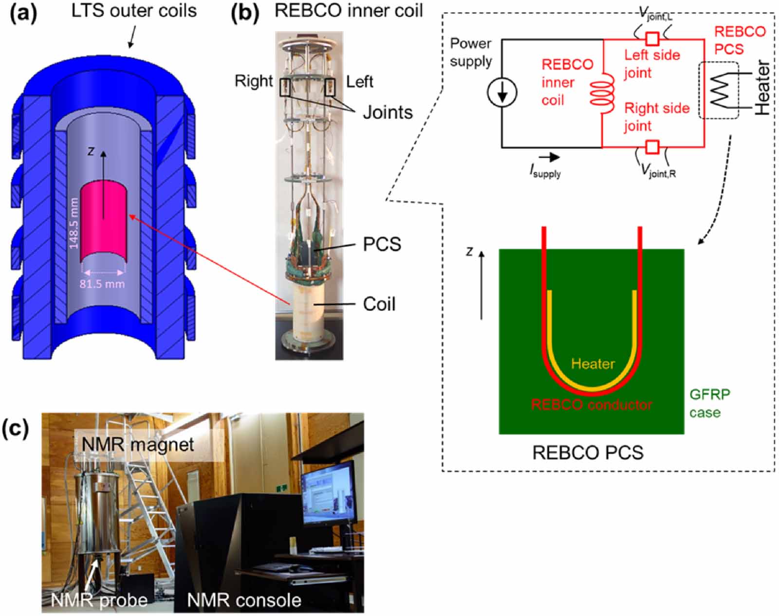
Table 1 describes physical parameters of a REBCO inner coil and LTS outer coils in a 400 MHz LTS/HTS NMR magnet. A schematic drawing of the coils and a photo of the REBCO inner coil are respectively shown in figures 1(a) and (b). The inner coil with a REBCO PCS and the outer coils with a NbTi PCS are operated in individual persistent current circuits; i.e. the magnet requires two power supplies for charging/discharging as explained later. In our development, we have employed layer-winding for HTS inner coils to reduce joint numbers and for simplicity of joint installation over the coil. In general, a PCS should be located in a low field area. However, we had to locate the REBCO PCS in a high field area just over the coil winding. This was because the furnace used for the joining process required a long length of the terminal conductors of a joint and this forced us to make such a non-ideal structure design. In recent work, we have developed a new furnace which does not need a long terminal conductor, enabling us to locate a PCS in a low field area. In the present work, we used the same type of REBCO conductors, manufactured by Sumitomo Electric Industries (SEI), for both the coil and the PCS. The details of the REBCO conductor configuration is described in the previous paper [26]. The NMR magnet with the LTS outer coils was manufactured by Japan Superconductor Technology, Inc.
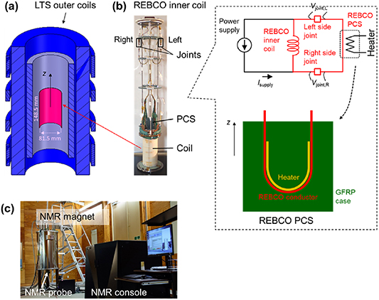
Figure 1. (a) A cross-sectional view of a persistent 400 MHz (9.39 T) LTS/REBCO NMR magnet. (b) A photo of the REBCO inner coil with an installed REBCO PCS terminated with iGS joints. The inset includes a schematic circuit of the REBCO inner coil in a self-field test and the structure of the REBCO PCS. (c) A photo of the NMR system.
Download figure:
Standard image High-resolution imageTable 1. Design physical parameters of a REBCO inner coil and LTS outer coils for a 400 MHz (9.39 T) LTS/HTS NMR magnet.
| Unit | REBCO inner coil | LTS outer coils | |
|---|---|---|---|
| Coil conductor | — | REBCO (SEI), without outermost copper electroplating layer | Nb3Sn and NbTi |
| Bare conductor width: thickness | mm | 4.05:0.14 | — |
| Insulated conductor width: thickness | mm | 4.1:0.19 | — |
| Conductor critical current at 77 K | A | ∼200 | — |
| Conductor length | m | 37.2 + 1.2 | — |
| ID: OD: Height | mm | 81.5:83:148.5 | 132.6:289.3:546 |
| Total turns | — | 144 | — |
| Number of layers | — | 4 | — |
| Coil constant | mT A−1 | 1.066 | 68.96 |
| Self inductance | H | 0.75 × 10⁻³ | 69.8 |
| Mutual inductance | H | 53 × 10−3 | |
| PCS conductor | — | REBCO (SEI), without outermost copper electroplating layer | NbTi/CuNi |
| Self-field operation at 77 K | |||
| Measured coil critical current | A | 123 (at 0.01 μV cm−1) | — |
| Measured PCS critical current | A | >107 (at 0.01 μV cm−1) | — |
| Self-field operation at 4.2 K | |||
| Estimated coil critical current | A | >1100 a | — |
| Estimated PCS critical current | A | >1100 a | — |
| 400 MHz operation at 4.2 K | |||
| Estimated coil critical current | A | >1100 a | — |
| Estimated PCS critical current | A | 370 b | — |
| Operating current | A | 92.70 | 134.8 |
| Magnetic field, Z0 | T: MHz | 0.09882: 4.207 | 9.296: 395.8 |
| Z2 harmonic | Hz cm−2 | 0.00 | |
| Z4 harmonic | Hz cm−4 | −211 | |
| Maximum hoop stress (BJR c ) | MPa | 63.3 | — |
| Local field intensity at joints | T | 0.2–0.6 | — |
a The critical current of the coil conductor or the PCS conductor was estimated based on a short sample Ic-B curve in parallel magnetic fields. b The critical current of the PCS conductor was estimated based on a short sample Ic-B curve in perpendicular magnetic fields since the magnetic field direction is normal to a part of the PCS conductor under the 400 MHz operation. c B, J, and R are axial magnetic field, conductor current density, and radius.
A JNM-ECZ series NMR spectrometer was fabricated by JEOL RESONANCE Inc., used for the NMR measurements. A photo of the NMR system is shown in figure 1(c).
An NMR magnet requires a magnetic field drift rate less than 0.01 ppm h−1 (10−8 h−1). For the present magnet, if the field drift of the LTS outer coils is neglected and the effect from the mutual inductance between the two coils is small, the total circuit resistance of the REBCO inner coil has to be <2 × 10⁻¹³ Ω to obtain a <1 ppm h−1 drift rate of the inner coil, resulting in a <0.01 ppm h−1 drift rate of the total magnetic field of 400 MHz. As shown in table 1, the estimated critical current of the REBCO inner coil in a 400 MHz operation (>1100 A) and that of the REBCO PCS (>370 A, Bnormal < 9.4 T) are much higher than the operating current of 92.7 A. Therefore, the effective resistance of the coil and PCS conductors is negligibly small. The following equation can be used if we suppose that the joint performance is expressed by the power law V–I characteristics:

Here Vc, Iop, Ic and n are a voltage criterion (1 μV), the operating current of the REBCO inner coil (92.7 A), the critical current of the joint and the n-index of the joint, respectively. Equation (1) gives Ic > 122 A (at n = 40), >133 A (at n = 30). This is the requirement for the small coil (0.75 mH) of the present study. The inductance for the future magnet will be much larger and the requirements for the critical current of the joints will be much easier.
Technical requirements for the REBCO PCS is shown in table 2. These values were determined based on the volume of liquid helium in the magnet, the time constant of the REBCO inner coil circuit of <10 s, and a reasonably quick switching time of the PCS, respectively.
Table 2. Required specifications of the PCS for the REBCO inner coil used in liquid helium.
| Heater power | <10 W |
| Off resistance | >0.1 mΩ |
| Switching time | <100 s |
3. In-field current transport characteristics of joint samples
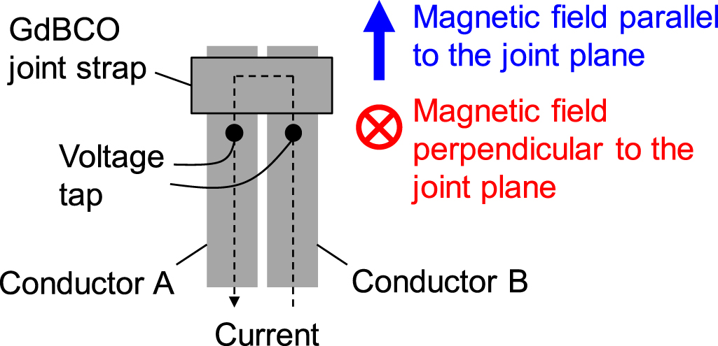
We measured current transport characterictics of two iGS joint samples in external magnetic fields in the range of 0–10 T at 77 K, 50 K and 4.2 K. Figure 2 shows a schematic drawing of a joint sample under measurement.
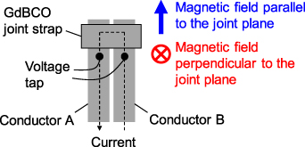
Figure 2. A schematic drawing of an iGS joint sample for measurement of in-field current transport characteristics.
Download figure:
Standard image High-resolution imageFigures 3(a) and (b) show the external magnetic field, Bex, dependences of Ic of samples #1 and #2, respectively. The right vertical axes show the Ic lift factor, defined by Ic/Ic(77 K, 0 T). Figures 3(a') and (b') respectively show the Bex dependences of the n-index of the samples. The fluctuations of n-values seen at 4.2 K are due to relatively lower signal-to-noise ratios of voltage-current data with steeper normal transitions.
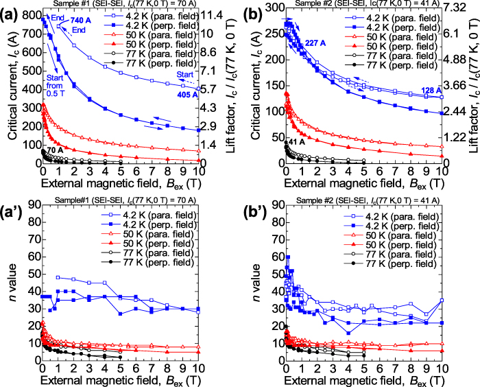
Figure 3. In-field current transport characteristics of two iGS joint samples. External field dependence of Ic: (a) sample #1/(b) sample #2. External field dependence of n value: (a') sample #1/(b') sample #2. Critical currents were determined at a 1 μV criterion. n values were determined with the voltage range of 0.1–1 μV.
Download figure:
Standard image High-resolution imageIn parallel fields at 4.2 K, the critical current Ic(1 T) was 740 A and Ic(10 T) was 405 A for sample #1 (see figure 3(a)); Ic(1 T) was 227 A and Ic(10 T) was 128 A for sample #2 (see figure 3(b)). These results show that an iGS joint can be used in a high magnetic field of >1 T, which is a significant advantage, compared to a superconducting joint between LTSs using solder [4]. The samples at any temperatures showed higher Ic in a parallel field than in a perpendicular field. The Bex dependences of the n-value for the samples are similar to those of Ic, and they show higher values at lower temperatures as shown in figures 3(a') and (b').
At 4.2 K in parallel fields, sample #2 showed a hysteresis of the Ic–Bex curve during the field ramp up and ramp down processes. This behavior implies that the joint structure includes weak-link current paths across grain boundaries [36].
These results on high critical currents of iGS joints in external magnetic fields, which are of the same order as that of a conductor, show the potential of the iGS joint being used over a wide range of temperatures and magnetic fields. In the 400 MHz LTS/HTS NMR magnet, the joints of the REBCO inner coil are located in the field range of 0.2–0.6 T. Therefore, it does not seem difficult to obtain a sufficiently high joint critical current, i.e. >133 A, considering the results in figure 3. However, improvement on the joint process control is still required for future magnets to provide stable high joint critical currents, as the characteristics in figure 3 depend on each sample. A joint with higher critical currents shows a higher lift factor. We believe that the critical current of an iGS joint is affected by the film quality near the surfaces of the REBCO layers, and we plan to improve it by smoothing the surfaces and optimizing the thickness of the joining layer.
4. Development of a REBCO PCS operated in liquid helium
We fabricated a model PCS for the REBCO inner coil, using a 140 mm-length REBCO conductor of the same type used for the coil winding described in table 1. The conductor was wound for a half turn in a fiber-reinforced plastic case (see the inset in figure 1(b)). A film heater was co-wound with the conductor for switching and was impregnated with paraffin. The performance of the model PCS was tested in liquid helium. Figure 4(a) shows off-resistance as a function of heater power. The resistance of the PCS arose at a heater power of 5.5 W and it showed 300 mΩ at 6 W. The off-resistance should be higher at a higher operating current. The transient behavior in switching-off at 6 W is shown in figure 4(b). The PCS voltage started to rise after 33 s of the initiation of heater input and achieved a steady state in 100 s. These PCS performances fulfilled the required specifications described in table 2.
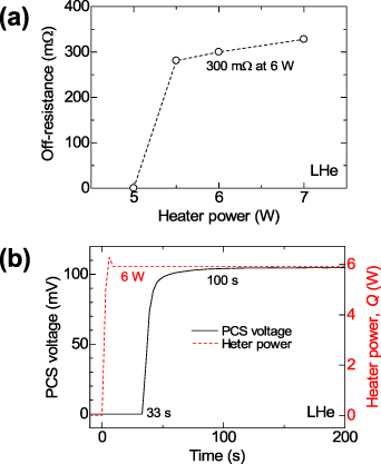
Figure 4. Performance of a model REBCO PCS in liquid helium. (a) Off-resistance versus heater power. The PCS shows 300 mΩ at 6 W. (b) Switch-off behavior with 6 W heater input. The PCS voltage is under constant current of 0.3 A.
Download figure:
Standard image High-resolution image5. Fabrication and self-field tests on a REBCO inner coil
We fabricated a REBCO inner coil as described in table 1. A PCS was made with the same physical parameters described in the previous section. We installed the PCS on the top flange of the coil (see figure 1(b)). The terminals of the coil and PCS were joined by the iGS joints. The inset for figure 1(b) includes a schematic circuit of the coil. After the joining processes, voltage taps, Vjoint,R and Vjoint,L (see the inset for figure 1(b)), and current leads were soldered to the joints. The joint parts were immersed in liquid nitrogen and we measured the joint Ic. The right side joint Ic and the left side joint Ic were 45.6 A and 17.3 A in self field, respectively. After the Ic measurements of the joints, we reinforced the terminal wiring of the coil and PCS to keep them from moving under electromagnetic forces. The joints were located in upper spaces over the coil (see figure 1(b)). We charged and operated the REBCO inner coil in a self-field in liquid helium (4.2 K). The coil central magnetic field was measured using a Hall sensor.
Before charging the coil, we verified the built-in PCS performance in the coil circuit operated in liquid helium. We increased the power supply current to 1 A in the PCS on-state, i.e. without heater input, as shown by the open circles in figure 5. The current flowed in the PCS-joints circuit and therefore the central magnetic field did not rise (see the open triangles in figure 5). After this, we increased the heater power in a stepwise fashion (see the open squares in figure 5) and a heater input of 5.4 W produced a switch-off operation to increase the central magnetic field (see the arrow in figure 5). The result demonstrated that a heater input of >6 W is sufficient to give an off-state of the PCS as indicated by the stand-alone test result of the model PCS shown in figure 4.
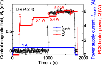
Figure 5. Built-in PCS performance in a self-field charging test of the REBCO inner coil. An off-operation of the switch was checked at the coil current of 1 A at 4.2 K through measuring the central magnetic field.
Download figure:
Standard image High-resolution imageWe charged the coil to 140 A under a PCS off-state with a 6 W heater input. After turning the PCS to the on-state, we decreased the power supply current to 0 A. During the power supply current reduction process from 140 A to 0 A, no normal transition was observed for both joints (Vjoint,R and Vjoint,L in figure 1(b)) and this indicates that the joint critical currents were higher than 140 A at 4.2 K.
Figure 6 shows magnetic field fluctuations during persistent-mode operation of the REBCO coil over 4 h. The measured field shows no significant decay to the accuracy of the Hall sensor, i.e. 0.01–0.1 mT. Compared to the exponential curves with characteristic resistances of 10−10 Ω (dashed line), 10−11 Ω (dashed-dotted line) and 10−12 Ω (dashed-double dotted line), the characteristic resistance of the central magnetic field decay is less than 10−11 Ω.
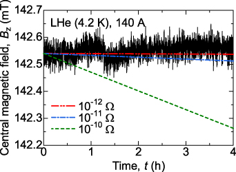
Figure 6. Measured magnetic field versus time of the REBCO inner coil operated at 140 A in liquid helium in a self-field. The dashed line, the dashed-dotted line and the dashed-double dotted line respectively show exponential curves with characteristic resistances of 10−10 Ω, 10−11 Ω and 10−12 Ω.
Download figure:
Standard image High-resolution imageAs described so far, we succeeded in operating the REBCO inner coil in the persistent-mode at 140 A, which is sufficiently higher than a required joint Ic of 133 A for a 400 MHz NMR operation.
6. Operation of the LTS/REBCO NMR magnet and NMR measurements
6.1. Construction and charging of the magnet
We installed the REBCO inner coil inside the LTS outer coil of a NMR magnet (see figure 1(a)) with a 54 mm room temperature (RT) bore. The LTS outer coil also has a NbTi PCS and therefore the REBCO inner coil and the LTS outer coil can be individually charged with two power supplies as shown in figures 7(a) and (b). For charging a coil, the PCS of the other coil has to be in the off-state, i.e. heater-on, since the two coils are magnetically coupled. The coils are cooled by liquid helium and the magnet has installed a 4 K pulse-tube cryocooler for zero boil off of liquid helium.
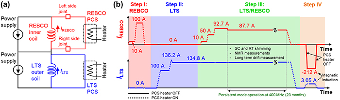
Figure 7. (a) Schematic circuit of the persistent-mode 400 MHz LTS/REBCO NMR magnet. Note that the LTS outer coil has joints which are not described in the figure. (b) A schematic of the operating process of the coil currents for the magnet.
Download figure:
Standard image High-resolution imageFigure 7(b) shows the operating process of the REBCO inner coil current, IREBCO, and the LTS outer coil current, ILTS. First, we charged the REBCO inner coil to 100 A and operated it in the persistent-mode for 88 h. The magnetic field showed no drift within the accuracy of the Hall sensor. After discharging the REBCO inner coil to 0 A, we charged the LTS outer coil to 100 A and operated it in the persistent-mode as shown in step II in figure 7(b). The magnetic field drifted with time in the positive polarity with drift rates of 0.36–0.11 ppm h−1. This drift is probably due to the relaxation of screening currents in the REBCO conductors induced by the radial magnetic field of the LTS outer coils. We increased ILTS to 134.8 A via 136.2 A, i.e. a 1% current sweep reversal, as shown in step II in figure 7(b). The magnetic field became very stable with a drift rate of −0.008 ppm h−1.
As shown by step III in figure 7(b), holding ILTS of 134.8 A, we charged the REBCO inner coil to 92.7 A and achieved a persistent-mode operation of the 400 MHz LTS/REBCO NMR magnet. The magnetic field at the left side joint measured with a Hall sensor was 0.25 T. As shown by figure 8(a), the drift rate of the magnetic field was 0.0744 ppm h−1 and decreased to 0.0144 ppm h−1. We infer that this positive field drift was due to the relaxation of screening currents in the REBCO inner coil.
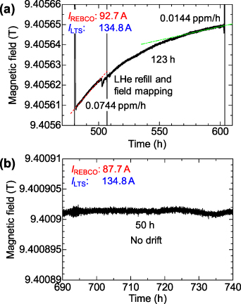
Figure 8. Drifts of the magnetic field for the LTS/REBCO NMR magnet in the persistent-mode. (a) A drift in Step III in figure 7(b): IREBCO = 92.7 A. ILTS = 134.8 A. (b) A drift in step III in figure 7(b): IREBCO = 87.7 A. ILTS = 134.8 A. The drifts were measured with an NMR Teslameter.
Download figure:
Standard image High-resolution image6.2. Field correction (shimming)
We measured the magnetic field profile along the coil axis using an NMR Teslameter (PT2025, Metrolab Technology SA) and the Z2 harmonic was as large as −2434 Hz cm−2 (−6.06 ppm cm−2). We decreased IREBCO to 87.7 A. This current change operation decreased the Z2 harmonic to −1187 Hz cm−2 (−2.97 ppm cm−2) and also gave a stable magnetic field as shown in figure 8(b), where no drift was observed within the 10−6 T (0.1 ppm) order accuracy of the NMR Teslameter.
We improved the spatial field homogeneity with NbTi superconducting shim coils for the field harmonics of Z, Z2, X, Y, ZX, ZY, C2, S2. The peak-to-peak amplitude of the magnetic field profile, measured with an NMR mapping system (FMU1200, Resonance Research, Inc.), was decreased from 22800 Hz (57 ppm) to 440 Hz (1.1 ppm) as shown in figure 9. The residual field error harmonics were compensated with copper RT shim coils installed in the RT bore of the magnet, which can control 44 types of field harmonics.
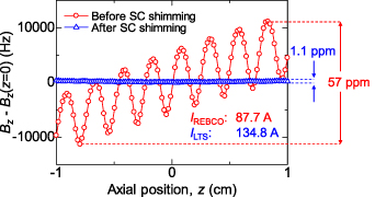
Figure 9. Magnetic field profiles of the persistent-mode 400 MHz LTS/REBCO NMR magnet with and without SC shimming. The profiles were measured with an NMR mapping system.
Download figure:
Standard image High-resolution image6.3. Evaluation of the magnetic field quality with high-resolution NMR measurements
The field of the NMR magnet must be extremely stable over years. After the RT shimming, we measured the magnetic field drift, as shown in figure 10, using a standard RT solution NMR probe without a field-frequency lock operation, which is a common field stabilization system using feedback control of the magnetic field [13]. Because of the improved spatial field homogeneity, i.e. spectrum resolution, we were able to track the change of the field more precisely. The magnetic field did not 'decay' and slightly increased with time due to the relaxation of screening currents induced in the REBCO inner coil. The drift rate was 0.84 × 10⁻³ ppm h−1, which is 10-fold lower than the typical required drift rate of the NMR magnet, <0.01 ppm h−1.
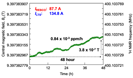
Figure 10. Magnetic field drift of the persistent-mode 400 MHz LTS/REBCO NMR magnet three weeks after the final adjustment of the magnetic field. The drift was measured using a room temperature (RT) solution NMR probe without a field-frequency lock operation. The magnetic field was obtained from the peak frequencies of NMR spectra of 1% chloroform in acetone-d6.
Download figure:
Standard image High-resolution imageFigure 11 shows the long-term stability of the magnetic field over two years measured by NMR signal observation of the same sample without the field-frequency lock operation. The positive drift rate became even smaller but was still slightly positive over two years after the magnet charge, mainly due to the relaxation of the screening current. The drift rate for the latter half of the measurement was 0.03 × 10⁻³ ppm h−1, which is 300-fold more stable than the typical required drift rate of the NMR magnet, <0.01 ppm h−1. The change of the Z2 harmonic was also observed. In the first month, this term changed by 1 Hz cm−2 every day, which was due to the relaxation of screening currents in the REBCO inner coil. We needed to shim manually every morning or apply automated shim adjustment (shim track) to keep recording high-resolution spectra. However, in two months, the harmonic change became negligibly small.
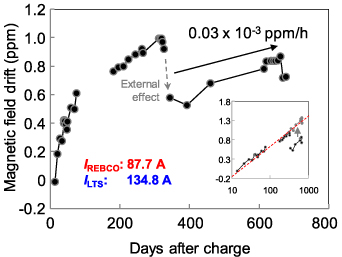
Figure 11. Magnetic field drift of the persistent-mode 400 MHz LTS/REBCO NMR magnet over two years. The peak frequency (i.e. magnetic field) of the 1H signal of chloroform (CHCl3) measured without field-frequency lock is plotted as a function of the number of days since the completion of superconducting shim adjustment. 0 ppm of the vertical axis corresponds to 400.1036 MHz. The effect of the room-temperature shim on the central magnetic field is subtracted. The perturbation from environmental factors was estimated as about 0.1 ppm. Among them, the internal He gas pressure caused an effect as large as 0.05 ppm. On day 340, the magnetic field changed by 0.4 ppm due to the installation of a large piece of equipment in the next room. The inset shows a plot with a logarithmic representation of the horizontal axis. The arrow indicates a correction of 0.4 ppm. The magnetic field changes continue to be proportional to the logarithm of time. After day 340, the field increased with a drift rate of 0.03 × 10⁻³ ppm h−1.
Download figure:
Standard image High-resolution imageAs the magnetic field seen in the inset of figure 11 varied linearly with logarithmic time, the positive field drift is mainly dominated by relaxation of the screening current. Since the REBCO inner coil and the LTS outer coil are each operated in their own persistent circuit, we need to be careful when evaluating joint resistance from the apparent central field change seen in figure 11. Let us calculate the magnetic field attenuation assuming that the resistance of the REBCO inner coil circuit (including two joints) is 2 × 10⁻¹³ Ω. In addition, the LTS outer coil circuit resistance ranges from 0 to 2 × 10⁻¹⁰ Ω; the latter is calculated from the allowable drift rate (0.01 ppm h−1) of LTS NMR magnets. The inductance matrix in table 1 shows that the magnetic field decay rate is 76–83 ppm yr−1. As shown in figure 11, the observed change in the magnetic field (although upward) is 0.26 ppm yr−1, that is three orders of magnitude smaller. In addition, the preservation of the magnetic field uniformity supports the judgment that the fields of the REBCO inner coil and the LTS outer coil are unchanged. It is difficult to extract the decay of the transport current because of the continuous change in the screening current, but it is certainly small enough for NMR applications. More detailed discussion of the joint resistance of the REBCO inner coil will be given in the next chapter.
The second requirement for the NMR magnet is the homogeneity of magnetic field in the sample space. This is generally evaluated by the line width of NMR signals. Because the NMR signal frequency is proportional to the magnetic field, the line width is also proportional to the spatial distribution of the magnetic field. We used a typical solution NMR 1H-13C probe, which was designed for 1H-NMR signal detection of a sample in a 5 mm diameter NMR tube that is 20 mm in height. Figure 12 shows a one-dimensional NMR spectrum of the standard sample in a line shape measurement, i.e. 1% chloroform; the half height line width of the spectrum gives the NMR spectrum resolution, corresponding to the spatial magnetic field distribution. The field inhomogeneity of 1 × 10⁻³ ppm is very small compared with that before RT shimming (see figure 9). The line widths measured at the lower levels (0.5% and 0.1% heights of the signal) indicates rare but larger field errors. These values are indicators for the type of field error and are often important for selective suppression of very strong solvent signals. The values of these line widths seen in figure 12 are sufficiently small for high-resolution NMR [13].
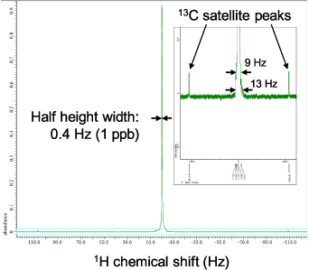
Figure 12. A 1D NMR spectrum of 1% chloroform in acetone-d6 obtained by the persistent-mode 400 MHz LTS/REBCO NMR magnet after room temperature shimming. The spectrum was obtained using a RT solution NMR probe under a field-frequency lock operation without sample spinning. To reduce the mechanical vibration of the magnet, the pulse-tube cryocooler was stopped for the measurement. The inset is the vertical expansion to see the bottom of the signal. The spectrum line widths at 50%, 0.5% and 0.1% heights are 0.4 Hz, 9 Hz and 13 Hz, respectively.
Download figure:
Standard image High-resolution imageThe spatial homogeneity of the magnetic field must be maintained for the period of NMR data collection. For the analysis of complicated molecules like proteins, several types of three-dimensional experiments are conducted. Each of them takes hours to days, depending on the signal intensity. Figure 13(a) shows a three-dimensional NMR spectrum for a protein sample obtained overnight. The HCCH-Total Correlation Spectroscopy (HCCH-TOCSY) [37] spectrum represents the carbon atoms in the same aliphatic chain in the molecule and is used for side-chain resonance assignment in the protein case. Figure 13(b) is a perspective view of the 13C-13C plane. Here, we can see roughly symmetrical distribution of signals. If the temporal stability was not sufficient, noise peaks would appear at unexpected positions. Such distortions and noises originating from temporal instability are below the threshold. The field homogeneity slowly changed. This originated from changes in the screening current in the REBCO inner coil and other environmental changes. For far longer data collection times, we can use the shim-track system to keep correcting the homogeneity because the homogeneity changes were suitably small and slow; the shim-track system periodically corrects several field error harmonics.
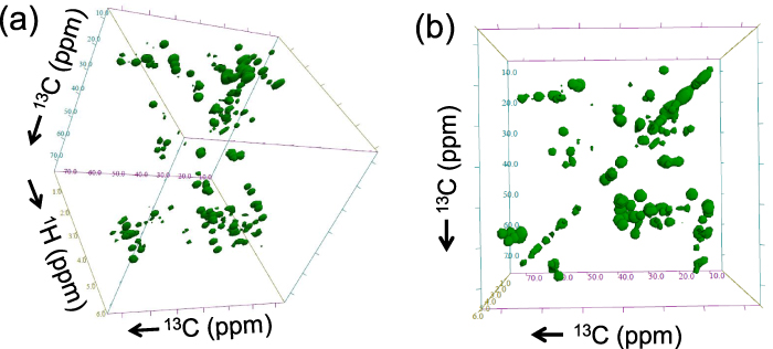
Figure 13. (a) A HCCH-TOCSY spectrum of 15N,13C-labeled 0.1 mM GB1 (protein G—B1 domain, 56 amino-acid residues) in D2O with phosphate buffer taken with the persistent-mode 400 MHz LTS/REBCO NMR magnet after RT shimming. The in-plane axes are 13C chemical shifts and the depth direction is 1H chemical shifts. The spectrum was obtained using a RT solution NMR probe under a field-frequency lock operation. (b) The perspective view of the 13C-13C plane of the spectrum.
Download figure:
Standard image High-resolution image6.4. Discharging of the magnet
After operating in the persistent-mode for over two years, we discharged the coils as indicated by lines in step III in figure 7(b). No notable voltage appeared on both the REBCO inner coil or the LTS outer coil when the power supplies were connected to the coils at 87.7 A and 134.8 A, respectively. This result directly demonstrates that the persistent coil currents were unchanged over two years.
As shown in Step IV in figure 7(b), after discharging the coils, we increased the LTS outer coil current to 3.05 A with the REBCO inner coil's PCS heater off, in order to measure the critical current of a joint by inducing an over current in the persistent circuit of the REBCO inner coil. A normal voltage appeared on the left side joint at IREBCO = 212 A (see the open circles in figure 14); this is the joint critical current. In addition, we measured the magnetic field drift for eight days and transformed the data to a voltage-current curve [29] as indicated by the closed circles in figure 14. The curve shows a substantially steep gradient with an n-index of 143.
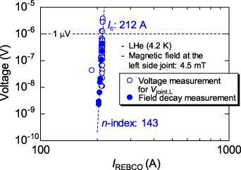
Figure 14. Voltage–current characteristics of the left side joint in liquid helium measured in step IV in figure 7(b). The data was obtained through a direct voltage measurement on the joint for a higher voltage region and a field decay measurement for a lower voltage region.
Download figure:
Standard image High-resolution imageBased on all the presented results, it is clear that the magnet constructed with iGS joints is both robust and stable over a long period of time, which satisfies the degree of magnetic field stability and homogeneity required for high-resolution solution-state NMR as well as solid state NMR.
7. Discussion
7.1. Estimation of the long-term joint resistance
Figure 11 shows that the long-term magnetic field drift rate over the second year, i.e. from the 340th day to the 670th day, is +0.26 ppm yr−1. As the magnetic field drift shown in the inset of figure 11 varied linearly with logarithmic time, the positive field drift is dominated by relaxation of the screening current [38].
Both the REBCO inner coil and the LTS outer coil are magnetically coupled together; the self-inductance of the REBCO inner coil is 0.75 mH, while that for the LTS outer coil is 68.96 H; the mutual inductance is 53 mH. A simple circuit analysis for the coil system gives the magnetic field change over the second year. The result is shown in table 3; the rows show the dependence on the REBCO coil circuit resistance (RREBCO), while the columns that on the LTS coil circuit resistance (RLTS). The effect of the screening current is disregarded.
Table 3. Dependency of the magnetic field drift rate over the second year (ppm yr−1) on the circuit resistance of the REBCO inner coil (RREBCO) and that of the LTS outer coil (RLTS).
| RREBCO = 2 × 10⁻¹³ Ω | RREBCO = 2 × 10⁻¹⁴ Ω | RREBCO = 2 × 10⁻¹⁵ Ω | RREBCO = 2 × 10⁻¹⁶ Ω | RREBCO = 2 × 10⁻¹⁷ Ω | RREBCO = 2 × 10⁻¹⁸ Ω | |
|---|---|---|---|---|---|---|
| RLTS= 2 × 10⁻¹⁰ Ω | −75.48 ppm yr−1 | 0.32 ppm yr−1 | 7.99 ppm yr−1 | 8.76 ppm yr−1 | 8.84 ppm yr−1 | 8.84 ppm yr−1 |
| RLTS = 2 × 10⁻¹¹ Ω | −82.35 ppm yr−1 | −7.53 ppm yr−1 | 0.04 ppm yr−1 | 0.80 ppm yr−1 | 0.88 ppm yr−1 | 0.88 ppm yr−1 |
If we assume the usual magnetic field change rate of 0.01 ppm h−1 for the LTS outer coil, RLTS is 2 × 10⁻¹⁰ Ω (the first line in table 3). For RREBCO >10−13 Ω, the high value of RREBCO dominates the negative change of the field, while for a low value of RREBCO <10−15 Ω, the positive change of the field is produced by the current induction in the REBCO inner coil due to the decay of the LTS coil current. Under this assumption, the REBCO joint resistance is inferred to be ∼10−14 Ω.
To the contrary, for the assumption with a smaller magnetic field change rate of the LTS outer coil of 0.001 ppm h−1, i.e. RLTS < 2 × 10⁻¹¹Ω (the second line in table 3), the negative change of the field is dominated by the REBCO inner coil current decay for RREBCO > 2 × 10⁻¹⁴ Ω; while the positive change is dominated by the LTS outer coil current decay for RREBCO < 2 × 10⁻¹⁶ Ω. Under this assumption, the REBCO joint resistance is inferred to be ∼10−15 Ω.
Therefore, we are incapable of uniquely determining the REBCO joint resistance, as the long-term magnetic field change rate of the LTS outer coil is undetermined; however, we can say for certain that it is at least <10−14 Ω. This is reasonable in light of the fact that a short sample iGS joint at 4.2 K in an external field of >1 T gives a joint resistance of the order of 10−14 Ω, which was measured by a group including several of the present authors [39].
7.2. Additional technical issues for a persistent 1.3 GHz LTS/HTS NMR magnet
Thus far we have demonstrated the successful operation of a 400 MHz high-resolution NMR magnet with superconducting joints between the REBCO conductors. Based on this result, we next discuss general technical issues for the persistent-mode 1.3 GHz LTS/HTS NMR magnet, a target of the ongoing JST-Mirai Program [33].
The basic design of the persistent-mode 1.3 GHz NMR magnet [33, 34] comprises a REBCO inner coil, a Bi-2223 middle coil, and LTS outer coils. All coils are connected in series and charged simultaneously, as (a) a high off-resistance PCS for the Bi-2223 coil has not been developed so far and (b) it is a better way to protect the magnet system in case of a quench. As superconducting joints are located 0.5–1 m above the coil winding, the magnetic field strength at the joints is <1 T. To achieve the required drift rate of <0.01 ppm h−1 (10−8 h−1), the total circuit resistance should be <3 × 10⁻⁹ Ω [33], requiring an individual joint resistance of <10−12 Ω, as about a hundred joints between HTS conductors are to be installed. Considering that the magnet operating current is ∼200 A, the joint critical currents must be >248 A for n = 40, or >266 A for n = 30. The in-field current transport property of the REBCO joint seen in figures 3(a) and (a') provides sufficient performance, while more efforts must be expended in improving the Bi-2223 joint performance [30–32].
In order to achieve a persistent-mode operation with a hundred of HTS joints, a high reliability and efficiency HTS joining process must be developed. Furthermore, the following issues must be addressed with regard to HTS joints; (a) an on-site evaluation method of the newly produced HTS joint and (b) adequate and simple repair process in case of joint failure.
Other issues which must be addressed are HTS conductor degradation due to the electromagnetic force. We occasionally encounter unexpected local degradation of the REBCO coil due to the effect of electromagnetic force. Even a negligible normal voltage caused by such conductor degradation collapses stable persistent current operation; enhancement of the electromagnetic stress due to screening current is a serious issue which needs to be addressed [40–45].
7.3. Extensibility of HTS joints
In the present paper, we have concentrated on superconducting joints used for NMR magnets operated at 4.2 K. However, the in-field current transport properties of superconducting joints between HTSs seen in figure 3 suggest a large impact on superconducting magnet technology.
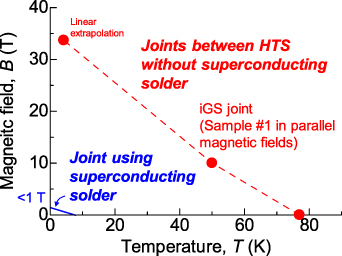
Typical superconducting joints used for the LTS NMR are a cold pressed NbTi joint, and a soldered NbTi/Nb3Sn joint where a copper matrix is replaced by superconducting solder. The former is usable up to 5 T and 8–10 K, while the latter up to 1 T and 7 K–8 K as its joint property is dominated by the superconducting solder, as depicted in figure 15.
Figure 15. Conceptual diagram of the magnetic field—temperature (B-T) plane of the performance of a superconducting joint. The circles are plotted based on the three Ic–B curves (77 K, 50 K and 4.2 K) of sample #1 in parallel magnetic fields shown in figure 3(a) with a threshold of a lift factor of 1.0. The value for 4.2 K was estimated by a linear extrapolation of the Ic–B curve.
Download figure:
Standard image High-resolution image
To the contrary, the intrinsic properties of the HTS material inside a HTS joint enable such a joint to be used over a very broad field-temperature (B-T) plane, as shown in figure 15. In fact, as shown in figure 3, iGS joints show high critical currents at 77 K and 50 K as well as 4.2 K; plots from Sample #1 are on the B-T plane as shown by circles in figure 15. These characteristics enable us to achieve a persistent-mode HTS magnet cooled by liquid nitrogen as well as by a cryocooler operated at >10 K [46–48].
However, attention must be paid to the following if the operating temperature of the magnet is to be increased, (a) the n-index for the superconducting joint decreases with temperature (see figure 3) and therefore a large Ic margin is necessary for the persistent magnet operation; (b) as the joint Ic decreases steeply with the magnetic field at a higher temperature, magnetic field shielding of a joint may be sometimes necessary.
8. Conclusions
We have fabricated a first prototype REBCO inner coil for a high-resolution NMR magnet which used superconducting joints between REBCO conductors (iGS joints). The coil was installed inside a LTS outer coil and they were operated as a persistent-mode 400 MHz (9.39 T) LTS/REBCO NMR magnet. We evaluated the magnet performance through NMR measurements. The results are summarized as follows.
- (a)A REBCO iGS joint sample showed very high current transport properties in external magnetic fields of 0–10 T at 4.2 K. These are vital characteristics for use in a magnet although we still have to improve the yield rate in the joining process.
- (b)A REBCO PCS operated in liquid helium was developed for a 400 MHz LTS/REBCO NMR magnet. The required specifications for heat input, off-resistance and switching time were fulfilled.
- (c)The 400 MHz LTS/REBCO NMR magnet was operated in the persistent-mode for two years, during which the REBCO inner coil generated ∼0.1 T. The magnetic field drift rate of the magnet showed 0.03 × 10⁻³ ppm h−1 and the 1H NMR spectrum line shape gave a half height width of 1 × 10⁻³ ppm, demonstrating that the superconducting joints functioned satisfactorily in a high-resolution NMR system. Based on the magnetic field drift over two years, the joint resistance is inferred to be <10−14 Ω.
Acknowledgments
This work was supported by the JST Mirai-Program funded by the Japan Science and Technology Agency. Grant Number JPMJMI17A2 and by Grant-in-Aid for JSPS Fellows funded by Japan Society for the Promotion of Science. Grant Number 19J11812. The authors appreciate Dr Junpei Hamatsu, Mr Taku Kawahara, Mr Yusuke Mori, Mr Yutaka Horino, Mr Takahiro Nemoto, and Mr Hiroto Suematsu of JEOL RESONANCE Inc. for the support of NMR measurements.
Data availability statement
All data that support the findings of this study are included within the article (and any supplementary files).