
Abstract
A series of La1−xCexNi1−yFeyO3 (x, y = 0.00–0.25) NPs was fabricated via micro-emulsion route and effect of doping was investigated on the basis of optical, photocatalytic and structural properties. The as-synthesized NPs were characterized via XRD, Raman analysis, SEM and UV–visible techniques. The XRD results confirmed the rhombohedral perovskite phase particles with particles of 60–80 nm range. UV–vis absorption edge showed significant red shift thereby tuning the band gap from 2.77 to 2.64 eV. The photocatalytic effectiveness of LaNiO3 and La0.80Ce0.20Ni0.80Fe0.20O3 catalysts was performed by degrading Congo red (CR) dye under visible light exposure. Substituted catalyst exhibited superior photodegradation by showing 97% degradation in comparison to pristine LaNiO3 (63% only) in 120 min. Degradation of CR followed the pseudo fist order kinetics. In addition, the catalyst dose effect, dye concentration and pH variation was studied for Cr dye degradation. Enhanced photocatalytic activity and narrow bandgap of Ce and Fe doped LaNiO3 introduce such materials as efficient visible active photocatalysts to be utilized in dye removal application from waste water and in photovoltaic applications, respectively.
Export citation and abstract BibTeX RIS

Original content from this work may be used under the terms of the Creative Commons Attribution 4.0 licence. Any further distribution of this work must maintain attribution to the author(s) and the title of the work, journal citation and DOI.
1. Introduction
In recent years, a great concern for health and environmental remediation has driven an inclusive interest to design and implement different materials and routes in removing the harmful and toxic pollutants from industrial waste water. Degradation of organic particulates in wastewater by oxidative photocatalysis has gained much attention [1–3]. Effluents from industrial units, i.e., textile, tanneries, leather, printing industries containing water soluble organic dyes are discharged into water bodies. These water-soluble organic dyes and other pollutants are thought to be the major source of water pollution as they are non-biodegradable and toxic, which impose a series health issues to humans, animals, plants and marine organisms [4–8]. Regrettably, only a few industrial units treat their wastes by different techniques including chemical, physical and biological approaches. But these methods are inadequate to remove pollutants effectively, which need advanced approach for the mitigation of pollutants [9–15]. Actually, these dye eradicating techniques have their own limitations, i.e., selective for specific dyes only, low removal efficiency, causing secondary pollution issue, and high operational cost. Hence, there is demand of efficient, novel, economic, ecofriendly approach for complete removal of these organic particulates from untreated water [10, 16–20]. In this regard, several chemical methods are employed extensively yet every technique has its own limitations [21–23]. Among the other chemical routes, the photodegradation using semiconductor metal oxides under solar irradiation has proved to be an efficient strategy and also it is ecofriendly and low-cost approach. Since as the solar spectrum comprises small fraction of UV (4%) and has high fraction of visible light (46%) so, in order to utilize this maximum fraction of visible light, it is necessary to fabricate novel efficient photocatalysts active under solar, which can be achieved by modifying the electronic structure and tuning the bandgap by doping [24, 25].
Recently, perovskite type metal oxides (ABO3) have been recognized as an efficient heterogeneous photocatalysts. In perovskites, the B-site transition metal ions are generally considered to be active for their catalytic property by involving their d-orbital electrons, while A-site rare earth containing cation in trivalent state are thought to be less decisive [1–3, 17, 26]. It is confirmed however that doping at A-site may remarkably improve the catalytic activity of the ABO3 perovskites through the pathways of tuning the electronic state of the B-site cations or/and creating vacancies (oxygen) in the crystalline structure. LaNiO3 (LNO) is one of the broadly studied perovskite metal oxides because of high stability, eco-benign and low energy band gap (2.26 eV). Doping at A/B, A-B site or its composite with other materials might be considered as an efficient strategy to enhance its photocatalytic performance. This strategy not only tunes the energy band gap, but also generates oxygen vacancies, which inhibit the photoinduced electron-hole recombination on photocatalyst surface thereby improving the catalytic efficacy [27]. Recently Zhang et. al reported the improved photocatalytic properties of LaNiO3/Ni3C composites for H2 evolution. Shahid and co-researchers displayed the high photo efficiency of La1−y Gdy Ni1−x Cox O3 NPs for the removal of RhB dye. Li et al also revealed the enhanced photocatalytic competence for La1−xCexNiO3 for MO dye degradation, which was highly promising. Zeng et al reported the superior photodegradation of MO by B-site substituted LaNi1−xFexO3 prepared via sol-gel route [28–31]. From literature point of view, photodegradation study of Ce and Fe doped LaNiO3 catalyst synthesized by microemulsion route has not been reported yet. Hence, a series of La1−xCexNi1−yFeyO3 NPs synthesized via micro-emulsion method and their photocatalytic efficiency was investigated CR dye degradation. Moreover, the effect of process variables, i.e., catalyst loading, dye dosage and pH variation on photocatalytic performance of La0.80Ce0.20Ni0.80 Fe0.20O3 was investigated in detail.
2. Material and methods
2.1. Reagents and chemicals
The salts and solvents like Ce(NO3)3.6H2O, La(NO3)3.6H2O, Ni(NO3)2.6H2O, Fe(NO3)2.9H2O and CTAB were acquired from Sigma Aldrich. The NH4OH and CR dye were purchased from the BDH.
2.2. Synthesis of La1−xCexNi1−yFeyO3
Various compositions of La1−xCexNi1−yFeyO3 (x, y = 0.00–0.25) NPs were synthesized by micro-emulsion technique at low temperature. For this, the aqueous solutions of all the respective metal nitrates were prepared in stoichiometric amount and were mixed according to composition scheme. All the mixed solutions were placed on hot plates with magnetic stirring and temperature was raised up to 80 °C. After attaining the required temperature, stirring was continued, but heating was switched off until room temperature was reached. Then, NH4OH was added drop wise to maintain the pH ∼11 and stirring was continued for 6 h. Then, precipitates were washed by distilled water several times to attain neutral pH and were dried overnight in oven at 100 °C. Finally, the calcined was performed at 700 °C for 6 h and subjected to characterization (figure 1S in supporting information available online at stacks.iop.org/MRX/8/085009/mmedia). Before calcination step, on adding aqueous ammonia solution lanthanum and nickel nitrate are converted into corresponding metal hydroxides, which on calcination temperature were decomposed finally into LaNiO3 [32]. (Equations (1)–(2)).


2.3. Characterization
The Xray diffraction analysis (X'Pert PRO diffractometer) in 20°–60° range was performed for structural analysis, whereas morphology was evaluated by SEM analysis (JOEL-JSM-6490LASEM). The Raman study was performed at 298 K by T6400 triple JobinYvon-Atago/Bussan spectrometer. Hitachi F-7000 spectrophotometer was used for photoluminescence spectrum (PL) studies. The UV-Vis studies were performed by employing Shimadzu 3101 UV–Vis spectrophotometer.
2.4. Dye degradation evaluation
The PCA of pure LaNiO3 and La0.80Ce0.20Ni0.80Fe0.20O3 NPs was investigated by studying the photodegradation of CR dye (figure 2S in supporting information) under solar light exposure (200 W Argon lamp). A 0.08 g of La0.80Ce0.20Ni0.80Fe0.20O3 was added to 200 ml of CR dye (10 mg l−1) along with 10 ml of H2O2 (10%). The mixture was kept in dark (stirred) for 0.5 h and placed in reactor for specific time intervals, then, a 5 ml of suspension was taken, filtered and absorbance was checked at λmax = 498 nm. The CR dye removal (%) was calculated (equation (3))

Where, Co and Ct represent the dye concentration at zero time and specific time 't', respectively.
3. Results and discussion
3.1. XRD analysis
Figure 1 depicts XRD analysis of La1−xCexNi1−yFexO3 compositions sintered at 700 °C in 2θ, i.e., 20°–60° range. The characteristic diffraction peaks appeared at 2theta i.e. 23.20°, 32.80°, 47.28 ° and 58.48° were indexed as (101), (110), (202) and (122) miller planes, which is a rhombohedral crystalline structure of the LaNiO3 (JCPDS # 034–1028) [33, 34]. For x, y = 0.05 and 1.0 compositions, the most intense peak at 32.80° was shifted slightly toward lower 2θ axis along with minor decline in intensity which indicated the successful substitution of Ce3+ and Fe3+ contents in perovskite structure thus causing some structural defects and reduction in crystallinity of doped compositions. This shifting might be ascribed to relatively low difference of ionic radii of Ce3+ (115 pm) and La3+ (117 pm) at A-site compared with Ni3+ (0.70 pm) and Fe3+ (0.64 pm) at B-site which induces structural defects [35, 36]. For compositions with x, y > 1.0 the most intense peak, i.e., 32.80° was declined significantly with origination of some additional low intensity peaks at 2θ = 27.5°, 43.2° and 45.8° in diffraction pattern which were assigned to La2O3 [JCPDS #83-1355), NiO [JCPDS #78-0643] and CeO2 [JCPDS #320196] phases present along with major perovskite phase. Peak at 27.5° was originated due to overlap of CeO2 and La2O3 phases [37]. It is reported that high doping content of Ce3+ ions in La1−x Cex NiO3, result in the segregation of Ce from perovskite phase in the form of CeO2 which clarify that some of the Ce ions existed as Ce4+ (0.98 pm) [38, 39]. Moreover, the segregation of CeO2 out of the perovskite phase is accompanied with NiO segregation, which is in accordance with the decline in La/Ni ratio, in addition to the fact that segregated CeO2 and NiO cannot react mutually to form perovskite structure [40]. Similar effects were also observed by Lima et al who synthesized La1−xCexNiO3 NPs with different concentration of Cerium ion (x = 0.00, 0.05, 0.4 and 0.7) via precipitation technique [38].
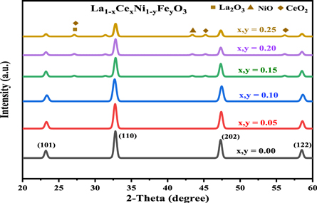
Figure 1. XRD patterns of various compositions of La1−xCexNi1−yFeyO3 (x, y = 0.00–0.25) sintered at 700 °C.
Download figure:
Standard image High-resolution imageCell volume (Vcell) was declined from 332.66 nm for pristine LNO to 330.10 nm for highest doping composition. The observed suppression in Vcell might be attributed again to significant ionic radii difference of B-site (Ni3+, Fe3+) cations than A-site (La3+, Ce3+) ions which results in decrease of lattice parameters and hence origination in lattice strain. The crystallite size related to most intense diffraction peak i.e. at 32.80° was calculated to be in 56–83 nm range. The increase in x-ray density (ρx−ray) values in substituted compositions might be due to doping of cations having greater atomic masses at host cations with lower masses as well as decline in Vcell on substitution onwards. While less values of bulk densities (ρm) in comparison to ρx−ray values was an indication of presence of some porosity in doped catalysts. The theoretical porosity calculated from ρm and ρx−ray data was calculated to be increased from 65.71% to 68% with increase in doping amount (table 1). The possible high porosity make such materials as efficient photocatalysts in degradation of dye effluents from industrial wastewater [27].
Table 1. Effect of Ce and Fe doping on various structural parameters of La1−xCexNi1−yFeyO3 (x, y = 0.00–0.25 ) NPs calcined at 700 °C.
| Doping amount (x, y) | 0.00 | 0.05 | 0.10 | 0.15 | 0.20 | 0.25 |
|---|---|---|---|---|---|---|
| Cell volume (Å)3 | 332.66 | 332.07 | 331.57 | 331.12 | 330.10 | 330.69 |
| Crystallite size (nm) | 60.35 | 65.24 | 67.73 | 72.22 | 79.29 | 74.15 |
| Xray density (gcm−3) | 6.142 | 6.167 | 6.174 | 6.179 | 6.192 | 6.186 |
| Bulk density (g/cm−3) | 2.106 | 2.101 | 1.995 | 1.989 | 1.981 | 1.984 |
| Porosity (%) | 65.71 | 65.93 | 67.63 | 67.74 | 68.00 | 67.92 |
3.1.2. Surface analysis
Figures 2(a)–(f) shows the FESEM micrographs of Ce and Fe doped LaNiO3 NPs. Almost all the compositions displayed relatively spherical and elongated shaped particles showing heterogeneous agglomeration having narrow range of grain size distribution. The approximated size analyzed from SEM micro images was calculated to be in 60–80 nm range which was found to be in agreement with XRD results (56–83 nm). The agglomeration of nanocrystallites might be due to fact that the nanoparticles having narrow dimensions and enough surface energy may merge together easily to form large clusters or aggregates [41]. This agglomeration was yet more significant in low doping compositions as demonstrated from SEM micrographs.

Figure 2. (A)–(F) SEM optical micrographs of La1−xCexNi1−yFeyO3 (x, y = 0.00–0.25) compositions.
Download figure:
Standard image High-resolution image3.1.3 Raman spectra
To get more insight in to the structure, La1−xCexNi1−yFexO3 (x, y = 0.00, 0.10 and 0.20) NPs Raman analysis was performed (figure 3(A)). Group theory proposes that LaNiO3 having rhombohedral structure with R3‾c space group shows five modes active in Raman spectrum: ΓRaman = A1g + 4Eg modes [42, 43]. Five main Raman peaks: Eg(1), Eg(2), Ag(1), Eg(3) and Eg(4) were observed at 71, 152, 209, 399, and 453 (cm−1), respectively. The band located at 71 cm−1 is out of recorded range of Raman spectra. Rotational–vibrational mode (Ag(1)) appeared at 209 cm−1 relates to an antiferrodistortive type soft mode of R3‾c structure (crystalline) [44]. Eg(3) mode might be attributed to the NiO6 octahedra vibrations. Broadening in Ag(1) and Eg modes was observed with increase in Ce and Fe concentration in LNO, this effect was however more pronounced in Ag(1) mode. The substitution of overall larger sized host cations by smaller sized substituted cations causes compressive strain in lattice at the both sites (tetrahedral and octahedral), which cause a blue-shift in Eg(2) and Eg(3) bands [45–47]. On increasing the doping content from x, y = 0.00 to 0.25, a shift of about 45 cm−1 in the Ag(1) mode was observed. Earlier reports propose that position of A1g mode in LaNiO3 might be scaled by almost ∼23 cm−1/° with tilting angle [42–44].

Figure 3. (A) Blue shifting in Ag(1) and Eg(3) modes of Raman spectra of Ce and Fe doped LaNiO3 and (B) Photoluminescence spectra showing decline in PL intensity of La1−xCexNi1−yFeyO3 (x, y = 0.00–0.25) NPs with increase in dopant concentration.
Download figure:
Standard image High-resolution image3.2. Optical analysis
3.2.1. Photoluminescence (PL) property
PL spectroscopy, being a reliable tool has been employed to analyze the electronic structure, migration and recombination of photoinduced electron-hole pair phenomenon in a material [48, 49]. The charge transferring rate of these light induced carriers is associated to intensity of PL peak, and the peak height specifies the rate at which holes and electron combine [50]. Figure 3(B) depicts the induced fluorescence intensity of all compositions of La1−xCex Ni1−yFeyO3 (x, y = 0.00–0.25) recorded at λexc = 480 nm. As the graph shows, the similar and symmetrical PL emission peaks were appeared at 538 nm for all the samples and their intensities were reduced onwards with increase in doping content in LNO crystal structure. This decline in intensity specifies the inhibitory character of doped elements in the recombination of e−, h+ thereby enhancing the charge separation and ultimately improving the photocatalytic performance of substituted LNO samples [27]. Probably, on substitution of host cations by Ce3+ and Fe3+ in perovskite structure, more electronic states are generated which inhibits the recombination of e−-h+ and efficiently stabilize the charge carriers in doped martials [51]. Among all the synthesized materials, the La0.80Ce0.20Ni0.80 Fe0.20O3 composition showed the weakest intensity of the PL emission peak. The decline in PL intensity was in consistent with the increase in charge separation or suppression in e−, h+ recombination, which suggested that the La0.80Ce0.20Ni0.80 Fe0.20O3 composition should impart improved photocatalytic performance by taking the advantage of its highest charge separation and lower recombination possibility of the photoinduced electron-hole pair.
3.2.2. UV-Visible analysis
To study the optical behavior of pure and doped LNO compositions, the UV–vis DRS spectra was recorded in 220–800 cm range (figure 4(A)). The Pure LNO sample displayed an absorption edge at around 378 nm. However, the absorption tail of substituted LNO samples was shifted towards visible region indicating red-shifting in absorption which showed the high visible active absorption of doped materials. The red-shift noticed in DRS might be due to the interaction between 3d orbital of Ni3+ and 3d orbital of Fe3+ which introduces intra-energy band gap states [27]. Further, the other possible reason for this shifting could be ascribed to charge-transferring transition between the valance and conduction bands of doping elements and LaNiO3 [51].

Figure 4. (a)–(b): (A) The UV–Vis diffuse reflectance absorption spectra and (B) Tauc's plot showing red shift in optical bandgap on substitution of Ce and Fe in LaNiO3.
Download figure:
Standard image High-resolution imageThe UV–visible absorption spectra of pristine LNO and La1−xCexNi1−yFeyO3 (x, y = 0.05–0.25) NPs is shown in figure 4(B). Tauc's model was employed to calculate the band gap energy (Eg) [52] (equation (4)).

Where, α and hν are the coefficient and photon energy of irradiation, while k and n denotes the type of transition, respectively. For pristine LNO, the Eg was found to be 2.77 eV while for x, y = 0.05–0.25 compositions declining trend in band gap i.e. 2.74–2.64 eV was noticed. The following causes might be accounted for this narrowing in band gap: (i) the generation of impurity energy band levels due to Fe3+ doping in LNO lattice, which occurred in center of CB and VB leading to reduction in Eg. (ii) charge transferring transition i.e. excitation of 3d orbital electrons of Fe3+ into conduction band of LNO (iii) or charge transfer between Fe3+ (Fe3+ + Fe3+ → Fe2+ + Fe4+) ions [27, 51].
3.3. Photocatalytic efficiency
The PCA of pristine LaNiO3 and La0.80Ce0.20Ni0.80 Fe0.20O3 NPs particles was calculated for CR dye. Figures 5(A)–(B) shows the spectra of the CR dye treated using pure and substituted LNO for 15 min under visible light exposure (CR dye + photo-catalyst). A 63% degradation of CR was observed in case of pure LNO after 120 min exposure of irradiation, however, the doped material (La0.80Ce0.20Ni0.80Fe0.20O3) exhibits improved PCA, i.e., >97%. The enhanced catalytic activity of substituted LNO might be ascribed to structural defects caused by substitution of cations having different ionic radii and electronic charge because oxygen or cation vacancies are generated to maintain the electro neutrality by small sized Ce4+ ions substituting large sized La3+ ions. Infact, dopants not only alter the energy band gap (Eg) of base (LNO), but also promote the e− and h+ and preclude them to recombine [53–55]. Table 2 shows the degradation comparison of CR by different photocatalytic reported earlier. The findings revealed that the La0.80Ce0.20Ni0.80 Fe0.20O3 NPs is highly efficiency for the removal of dyes. Also, in view of present condition of ecological contamination [56–61], to develop and employ the efficient approaches for the mitigation of toxic pollutants [23, 62–64] is obligatory and La0.80Ce0.20Ni0.80 Fe0.20O3 NPs under visible light irradiation is highly promising in this regard.

Figure 5. UV-Visible spectra of Congo red dye treated by, (A) LaNiO3 and (B) La0.80Ce0.20Ni0.80 Fe0.20O3 NPs as a function of increase in irradiation time.
Download figure:
Standard image High-resolution imageTable 2. Efficiency of some photocatalysts reported and present investigation for photodegradation of CR dye.
| Photocatalyst | Dye | %Removal | Time (min) | References |
|---|---|---|---|---|
| CuO nanorods | CR | 67 | 180 | [65] |
| NiO NPs | CR | 84 | 160 | [66] |
| MnFe2O4/TA/ZnO | CR | 84.2 | 90 | [67] |
| Ni0.2Cu0.8Al2O4 | CR | 90.5 | 180 | [68] |
| g-C3N4/RGO/BFO | CR | 87 | 60 | [69] |
| ZnO-CuO/ES | CR | 83 | 240 | [70] |
| fs-CoFe2O4 | CR | 92 | 180 | [71] |
| La1−xCexNi1−yFeyO3 | CR | 97 | 120 | This study |
In comparison to above mentioned photocatalysts, Ce and Fe substituted LNO photocatalyst in present study showed improved photodegradation efficiency. The Langmuir–Hinshelwood model was used for kinetic study (equation (5)).

Where, -dC/dt is the degradation rate with time (t), whereas kr and kc represent the photoreaction rate constants and dye adsorption coefficient, respectively. Equation (5) can be modified to equation (6).

Where, k (min−1) denotes rate constant. At time t = 0 min and C = Co. Equation (6) changes to equations (7) and (8).


The relation −lnCt/Co versus time (t) was employed to estimate the rate constant (k) [72–74]. The linear fittingf of −1lnCt/Co verses time (t) reveals that CR due followed first order kinetics (figures 6(A)–(C)). Rate constants for pristine LNO and La0.80Ce0.20Ni0.80 Fe0.20O3 for CR dye degradation under visible irradiation were 0.0084 and 0.012 (min−1) respectively.

Figure 6. Photodegradation removal efficiency (A) plot of Co/Ct versus irradiation time, (B) and rate constant and (C) photodegradation of Congo red dye over LaNiO3 and La0.80Ce0.20Ni0.80 Fe0.20O3.
Download figure:
Standard image High-resolution image3.4. Effect of reaction parameters on dye degradation
3.4.1 Catalyst dosage
The rate of photodegradation of dyes is considered to be influenced by the concentration of catalyst dose. The effect of La0.80Ce0.20Ni0.80Fe0.20O3 catalyst dose on CR dye removal using catalyst dose 10 to 40 mg/100 ml dye solution and the degradation rates were 0.0116, 0.0126, 0.0130, 0.0120 (min−1) for 10–40 mg/100 ml, respectively (figure 7(A)). Outcome showed that rate of degradation was augmented with the catalyst dose up to 30 mg and declined beyond this dose. Low rate of degradation at low catalyst dose may probably due to fact that more light gets transmitted through the reaction mixture and minor transmitted will only be consumed in photocatalytic reaction. At high concentration of catalyst loading however, the increase in photodegradation is due to active sites on the catalyst surface due to doping [27]. This is essentially due to increase in number of hydroxyl ions generated on illumination of catalyst. After applying the optimum dosage of catalyst, the decline in rate of reaction attribute to opacity of reaction mixture, which causes scattering of light. Also, the agglomeration of photocatalyst particles at higher dose results in decline in active sites accessible for catalytic degradation thereby deactivating the activated molecules by the collision with those of in ground states [51].

Figure 7. (A) Effect of catalyst dose, (B) dye concentration and (C) pH on kinetics of degradation of Congo red by La0.80Ce0.20Ni0.80 Fe0.20O3 NPs.
Download figure:
Standard image High-resolution image3.4.2. Dye initial concentration
The dye concentration impact on the removal of dye was considered in 10–40 mg l−1 range using the optimum dose of catalyst, i.e., 30 mg l−1. The values of rate constants for aforementioned concentrations of dye were 0.0130, 0.0136, 0.0119, 0.012 min−1 respectively. Outcome displayed that rate of degradation was enhanced with the dye concentration up to 20 mg L−1 and then, it was declined (figure 7(B)). Infact, the generation of radicals (hydroxyl·) on the surface of catalyst and reaction between OH• radicals and dye molecules was higher, which enhanced the dye removal. Initially, on increasing the concentration of dye more dye ions are available for excitation as well as for energy transfer [51]. This is due to the adsorption of dye on the surface (catalyst), which is favored at higher dye concentration until on reaching the critical level, the catalyst surface becomes fully covered leading to constant rate of reaction [27]. Decline in degradation efficacy at higher concentration of dye, on the other hand happens due to several reasons. On increasing the conc. of dye, more dye ions are getting adsorbed on catalyst surface and major extent of visible light is absorbed by the dye molecules, which may decrease the light penetration and resultantly, dye removal rate was diminished [51]. The active sites was occupied dye ions, generation of hydroxyl radicals may also be decreased. The intermediates adsorbed on the catalyst surface also impedes the hydroxyl radical generation, which declined the CR dye removal [27].
3.4.3. Effect of pH
Figure 7(C) shows the impact of pH on PCA of La0.80Ce0.20Ni0.80Fe0.20O3 catalyst for CR dye removal. The rate constants for photodegradation of CR at various pH values were calculated as 0.0096, 0.0102, 0.011 and 0.0092 min−1 respectively. Results depicted that rate constant was increased up to pH 8.0 after that it was decreased for pH 10. This trend in variation of photoreaction might be due to the formation of oxygen anion O2− radical due to the reaction between photoinduced e− and O2 molecules, which facilitates the rate of photocatalytic degradation process. Decline in degradation rate with increase in pH might be ascribed to repulsive forces between the negatively charged surface of La0.80Ce0.20Ni0.80Fe0.20O3 and anionic species. In acidic pH range, it is probable that a large amount of conjugate base (Cl− ions) may be increased in the solution. A possible reaction might be occurred between Cl− ions and OH• radicals thus producing ClO−• radicals, which being less reactive in comparison to OH• radicals may result a decrease in rate of photodegradation reaction [27].
3.5. Photodegradation mechanism
Photocatalytic degradation of CR due depends upon the electron/hole pairs, which is related to band gap energy [24]. Upon irradiation, the electrons (e−) in valance band (VB) of La0.80Ce0.20Ni0.80Fe0.20O3 by absorbing light energy ≥ band gap, are excited to conduction band (CB) leaving behind the holes (h+) in valance band (VB). Reaction between the photo excited electron and O2 produce O2 •− radical and finally, this is converted in to HOO• radical, which changes in to HO• radical by reacting with water molecule (figure 8). This HO• destruct dye by oxidation mechanism into pbyroducts [51]. Photoinduced holes in valance band (hVB +) also yield HO• radicals by breaking down the water molecule, which directly involve in degradation of dye [27]. There is possibility of recombination of photoinduced e− and h+, which may suppress the degradation competence of the catalyst. The chance of this possible recombination can be minimized by creation of structural defects, lattice distortion and oxygen anion (O2−) vacancies catalyst. Perovskite based catalysts with lattice distortion provide a pathway for the suppression of e−–h+ recombination thereby displaying better catalytic competence. Actually, these oxygen anion vacancies in perovskite structure enhance O2 adsorption onto the catalyst surface, thus improving the degradation efficacy. Doped catalysts generate HO• species, which degrade the dye into H2O and CO2 and inorganic ions [1, 2, 27, 51, 75] (equations (9)–(13)). The effect of different scavengers on the degradation of CR dye over La0.80Ce0.20Ni0.80Fe0.20O3 was studied using KI, Ascorbic acid and n-butanol as scavengers and response is presented in supporting information.


Figure 8. Schematic illustration of the reaction mechanism involved during photocatalysis of La0.80Ce0.20Ni 0.80Fe0.20O3 NPs for the photodegradation of Congo red dye.
Download figure:
Standard image High-resolution image
4. Conclusion
Herein we report the Ce and Fe substituted LaNiO3 NPs synthesized successfully by micro-emulsion approach and the influence of doping (Ce and Fe) on structural and phtotocatalytic properties of LaNiO3 in detail. The rhombohedral crystalline phase of as-prepared NPs was established from XRD results. SEM results showed relatively clustering and agglomeration in particles with average crystallite size in 60–80 nm range. Optical bandgap was decreased from 2.77 eV for pure LaNiO3 to 2.64 eV for x, y = 0.20 doped catalyst. Photocatalytic activities of pure and La0.80Ce0.20Ni0.80Fe0.20O3 were analyzed by degradation of CR dye under visible illumination. Substituted catalyst exhibited superior photocatalytic performance in comparison to pristine LaNiO3 which might be ascribed to suppression of photoinduced electron-hole recombination in consistent with significant decline in PL intensity. Improved photocatalytic activity of La0.80Ce0.20Ni0.80Fe0.20O3 makes them useful materials to be used as efficient photocatalyst active under visible irradiation for photodegradation of dyes in wastewater.
Acknowledgments
This research was funded by the Deanship of Scientific Research at Princess Nourah bint Abdulrahman University through the Fast-track Research Funding Program.
Data availability statement
The data that support the findings of this study are available upon reasonable request from the authors.