Low Cost, Lightweight Gravity Coring and Improved Epoxy Impregnation Applied to Laminated Maar Sediment in Vietnam


Abstract
:1. Introduction
2. Materials and Methods
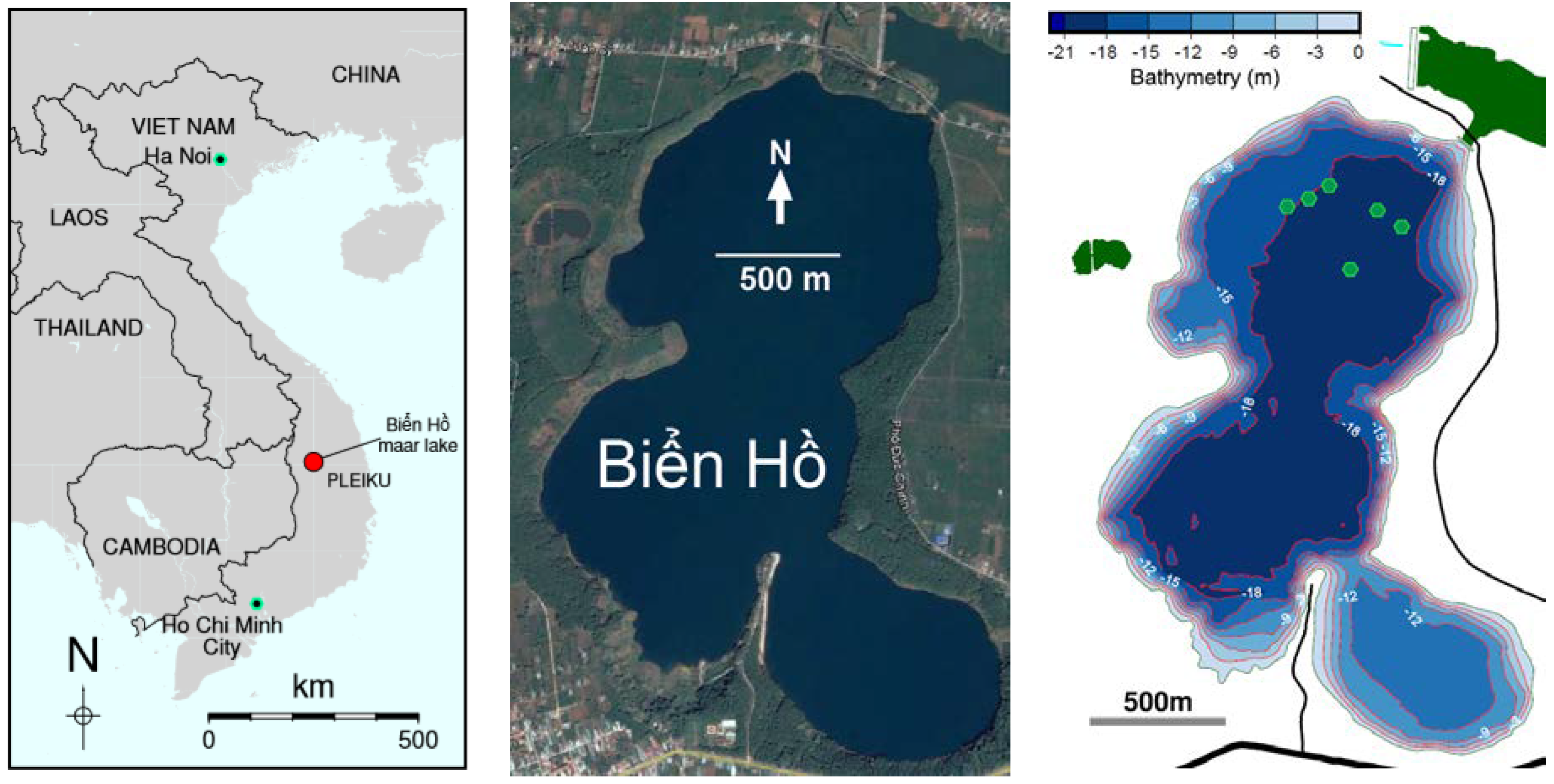
2.1. Maar Site Description
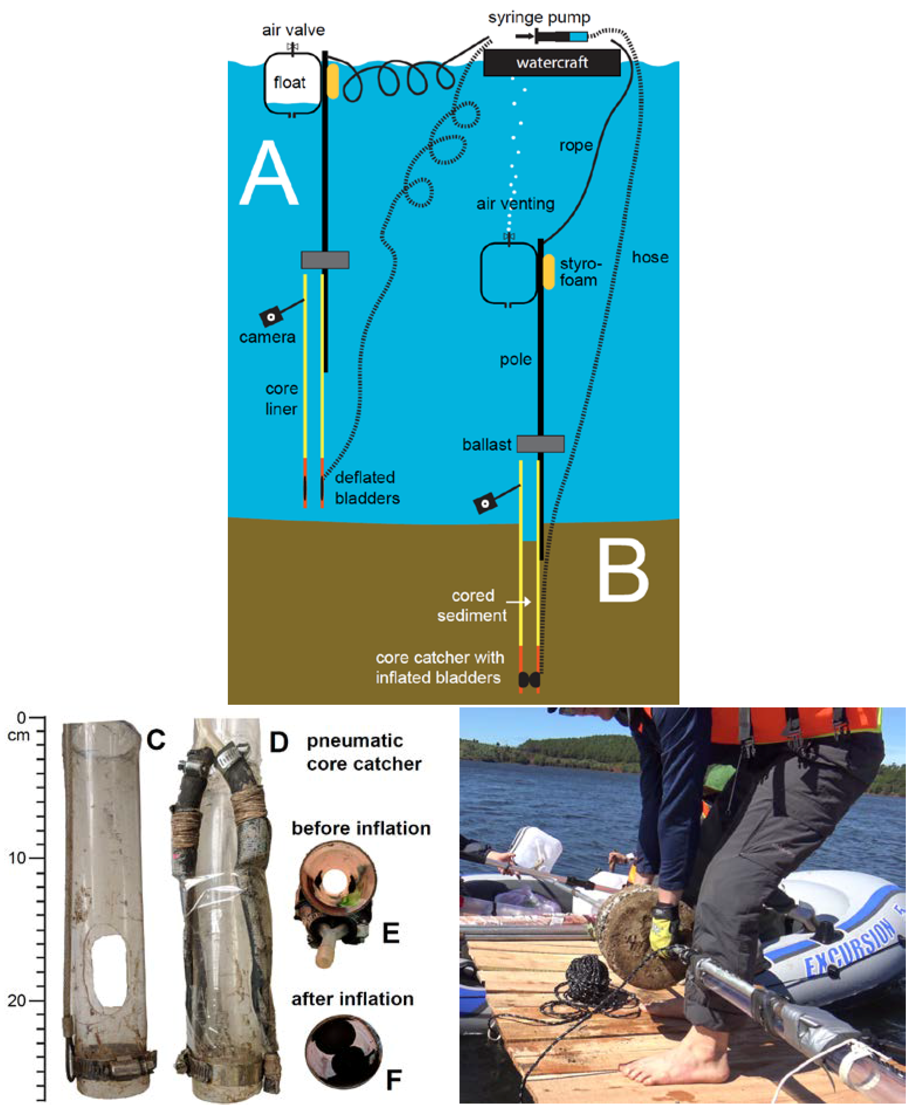
2.2. Autonomous Gravity Corer with Pneumatic Core Catcher
2.2.1. Construction and Function
2.2.2. Deployment
2.2.3. Recovery
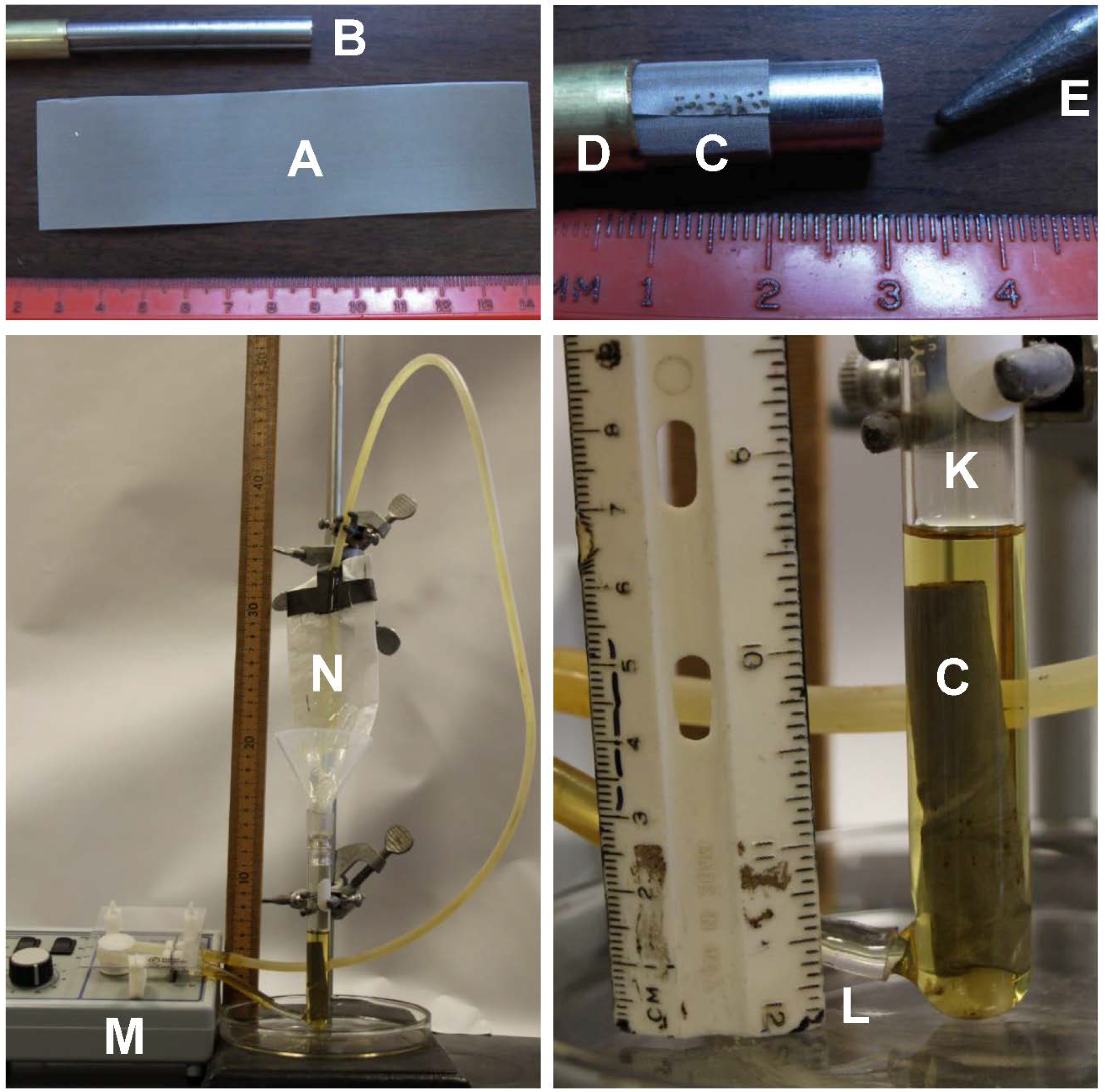
2.3. Rapid Spurr Epoxy Impregnation of Mini-Subcores
3. Results
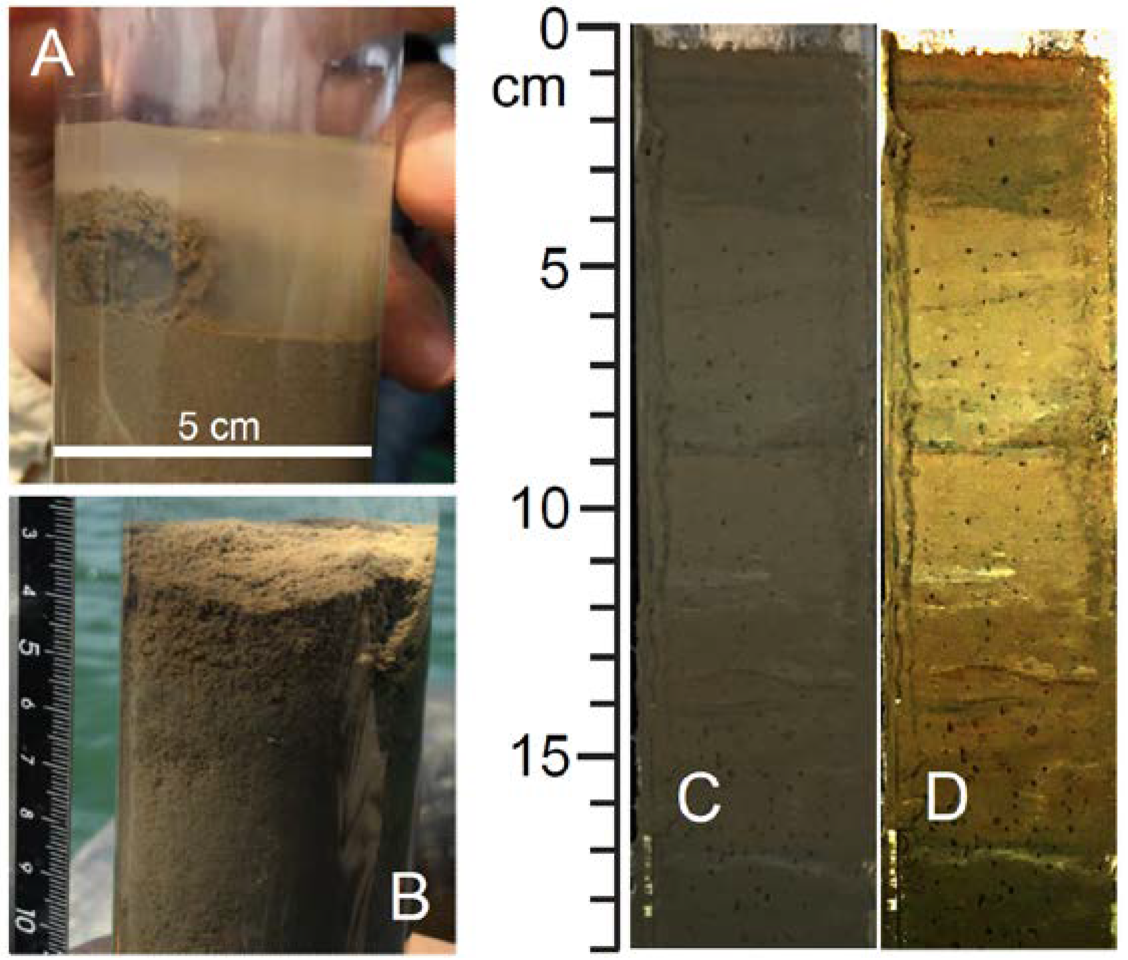
3.1. Coring
3.2. Epoxy Impregnation
4. Discussion
4.1. Autonomous Gravity Corer
4.2. Epoxy-Impregnation
5. Conclusions
Author Contributions
Acknowledgments
Conflicts of Interest
References
- Zolitschka, B.; Francus, P.; Ojala, A.E.K.; Schimmelmann, A. Varves in lake sediments—A review. Quat. Sci. Rev. 2015, 117, 1–41. [Google Scholar] [CrossRef]
- Schimmelmann, A.; Lange, C.B.; Schieber, J.; Francus, P.; Ojala, A.E.K.; Zolitschka, B. Varves in marine sediments: A review. Earth Sci. Rev. 2016, 159, 215–246. [Google Scholar] [CrossRef]
- Sun, Q.; Shan, Y.; Sein, K.; Su, Y.; Zhu, Q.; Wang, L.; Sun, J.; Gu, Z.; Chu, G. A 530 year long record of the Indian Summer Monsoon from carbonate varves in Maar Lake Twintaung, Myanmar. J. Geophys. Res. 2016, 121, 5620–5630. [Google Scholar] [CrossRef]
- Yang, Y.; Zhang, H.; Chang, F.; Meng, H.; Pan, A.; Zheng, Z.; Xiang, R. Vegetation and climate history inferred from a Qinghai Crater Lake pollen record from Tengchong, southwestern China. Palaeogeogr. Palaeoclimatol. Palaeoecol. 2016, 461, 1–11. [Google Scholar] [CrossRef]
- Yang, S.; Ding, Z.; Li, Y.; Wang, X.; Jiang, W.; Huang, X. Global temperature change as the ultimate driver of the shift in the summer monsoon rain belt in East Asia. Proc. Natl. Acad. Sci. USA 2016, 113, E2211–E2212. [Google Scholar] [CrossRef] [PubMed]
- Nguyễn-Văn, H.; Nguyễn-Thùy, D.; Schimmelmann, J.P.; Zolitschka, B.; Tạ-Văn, T.; Nguyễn-Ánh, N.; Tạ Hòa, P.; Đặng-Phương, T.; Lê-Quyết, T.; Nhi Phạm-Nữ, Q.; et al. Exploring the Paleoenvironmental Potential of Laminated Maar Sediment in Central Vietnam: An Archive of Regional Paleo-Flooding? In Proceedings of the PAGES 5th Open Science Meeting, Zaragoza, Spain, 9–13 May 2017; p. 325. [Google Scholar]
- Spurr, A.R. A low-viscosity epoxy resin embedding medium for electron microscopy. J. Ultrastruct. Res. 1969, 26, 31–43. [Google Scholar] [CrossRef]
- Clark, J.S. Stratigraphic charcoal analysis on petrographic thin sections: Application to fire history in northwestern Minnesota. Quat. Res. 1988, 30, 81–91. [Google Scholar] [CrossRef]
- Boës, X.; Fagel, N. Impregnation method for detecting annual laminations in sediment cores: An overview. Sediment. Geol. 2005, 179, 185–194. [Google Scholar] [CrossRef]
- Smith, S.J.; Anderson, R.S. A method for impregnating soft sediment cores for thin-section microscopy. J. Sediment. Res. 1995, 65, 576–577. [Google Scholar] [CrossRef]
- Card, V.M. Varve-counting by the annual pattern of diatoms accumulated in the sediment of Big Watab Lake, Minnesota, AD 1837–1990. Boreas 1997, 26, 103–112. [Google Scholar] [CrossRef]
- Lotter, A.F.; Lemcke, G. Methods for preparing and counting biochemical varves. Boreas 1999, 28, 243–252. [Google Scholar] [CrossRef]
- Schimmelmann, A. Varve-Related Master Reference List Compiled for the PAGES Varve Working Group (VWG) Containing >1750 References. 2018. Available online: http://pastglobalchanges.org/download/docs/working_groups/vwg/2018-varves-publicns-feb.pdf (accessed on 1 May 2018).
- Schimmelmann, A.; Riese, D.J.; Schieber, J. Fast and Economical Sampling and Resin-Embedding Technique for Small Cores of Unconsolidated, Fine-Grained Sediment. In Proceedings of the 2015 Pacific Climate (PACLIM) Workshop, Asilomar Conference Grounds, Pacific Grove, CA, USA, 8–11 March 2015. [Google Scholar]
- Nguyễn, H.; Flower, M.F.J.; Cung, T.C.; Phạm, T.X.; Hoàng, V.Q.; Trần, T.S. Collision-induced basalt ruptions at Pleiku and Buôn Mê Thuột, south-central Viet Nam. J. Geodyn. 2013, 69, 65–83. [Google Scholar] [CrossRef]
- Glew, J.R.; Smol, J.P.; Last, W.M. Sediment core collection and extrusion. In Tracking Environmental Change Using Lake Sediments, Volume 1: Basin Analysis, Coring, and Chronological Techniques; Last, W.M., Smol, J.P., Eds.; Kluwer Academic Publishers: Dordrecht, The Netherlands, 2002; pp. 73–106. [Google Scholar]
- Tomkins, J.D.; Antoniades, D.; Lamoureux, S.F.; Vincent, W.F. A simple and effective method for preserving the sediment-water interface of sediment cores during transport. J. Paleolimnol. 2008, 40, 577–582. [Google Scholar] [CrossRef]
- United Nations, Viet Nam Office. Details for Viet Nam: Floods Central Viet Nam-Office of the Resident Coordinator Situation Report No. 1. 2016. Available online: http://un.org.vn/en/publications/doc_details/533-viet-nam-floods-central-viet-nam-office-of-theresident-coordinator-situation-report-no-1.html (accessed on 1 May 2018).
- Baerwald, R.J.; Burkett, P.J.; Bennett, R.H. Techniques for the preparation of submarine sediments for electron microscopy. In Microstructure of Fine-Grained Sediments: From Mud to Shale; Bennett, R.H., Bryant, W.R., Hulbert, M.H., Eds.; Springer: Berlin, Germany, 1991; pp. 309–320. [Google Scholar] [CrossRef]
- Curry, K.J.; Bennett, R.H.; Mayer, L.M.; Curry, A.; Abril, M.; Biesiot, P.M.; Hulbert, M.H. Direct visualization of clay microfabric signatures driving organic matter preservation in fine-grained sediment. Geochim. Cosmochim. Acta 2007, 71, 1709–1720. [Google Scholar] [CrossRef]
- Schieber, J.; Southard, J.B.; Kissling, P.; Rossman, B.; Ginsburg, R. Experimental deposition of carbonate mud from moving suspensions: Importance of flocculation and implications for modern and ancient carbonate mud deposition. J. Sediment. Res. 2013, 83, 1025–1031. [Google Scholar] [CrossRef]
- Frews, C. Coring methods. In Geomorphological Techniques; Ch. 4.1.1; British Society for Geomorphology, 2014; Available online: http://geomorphology.org.uk/sites/default/files/geom_tech_chapters/4.1.1_Coring.pdf (accessed on 1 May 2018).
- LacCore, National Lacustrine Core Facility, University of Minnesota. Coring Devices. Available online: http://lrc.geo.umn.edu/laccore/devices.html (accessed on 1 May 2018).
- Unoson Environment AB, Beeker-Sampler, Mölnlycke, Sweden. Available online: https://www.unoson.se/produkt/beeker-sampler/ (accessed on 1 May 2018).
- Belbin, S.P. A new standard method of impregnation using crystic resin. J. Sediment. Res. 1994, 64, 673. [Google Scholar] [CrossRef]


© 2018 by the authors. Licensee MDPI, Basel, Switzerland. This article is an open access article distributed under the terms and conditions of the Creative Commons Attribution (CC BY) license (http://creativecommons.org/licenses/by/4.0/).
Share and Cite
Schimmelmann, J.P.; Nguyễn-Văn, H.; Nguyễn-Thuỳ, D.; Schimmelmann, A. Low Cost, Lightweight Gravity Coring and Improved Epoxy Impregnation Applied to Laminated Maar Sediment in Vietnam. Geosciences 2018, 8, 176. https://doi.org/10.3390/geosciences8050176
Schimmelmann JP, Nguyễn-Văn H, Nguyễn-Thuỳ D, Schimmelmann A. Low Cost, Lightweight Gravity Coring and Improved Epoxy Impregnation Applied to Laminated Maar Sediment in Vietnam. Geosciences. 2018; 8(5):176. https://doi.org/10.3390/geosciences8050176
Chicago/Turabian StyleSchimmelmann, Jan P., Hướng Nguyễn-Văn, Dương Nguyễn-Thuỳ, and Arndt Schimmelmann. 2018. "Low Cost, Lightweight Gravity Coring and Improved Epoxy Impregnation Applied to Laminated Maar Sediment in Vietnam" Geosciences 8, no. 5: 176. https://doi.org/10.3390/geosciences8050176