Control Strategy for Vehicle Inductive Wireless Charging Based on Load Adaptive and Frequency Adjustment


School of Transportation Science and Engineering, Beihang University, Beijing 100191, China
*
Authors to whom correspondence should be addressed.
Energies 2018, 11(5), 1222; https://doi.org/10.3390/en11051222
Submission received: 1 April 2018
/
Revised: 3 May 2018
/
Accepted: 4 May 2018
/
Published: 10 May 2018
(This article belongs to the Special Issue The International Symposium on Electric Vehicles (ISEV2017))
Abstract
:Wireless charging system for electric vehicles is a hot research issue in the world today. Since the existing research on wireless charging is mostly forward-looking aimed at low-power appliances like household appliances, while electric vehicles need a high-power, high-efficiency, and strong coupling wireless charging system. In this paper, we have specifically designed a 6.6 KW wireless charging system for electric vehicles and have proposed a control strategy suitable for electric vehicles according to its power charging characteristics and existing common wired charging protocol. Firstly, the influence of the equivalent load and frequency bifurcation on a wireless charging system is analyzed in this paper. Secondly, an adaptive load control strategy matching the characteristics of the battery, and the charging pile is put forward to meet the constant current and constant voltage charging requirements to improve the system efficiency. In addition, the frequency adjustment control strategy is designed to realize the real-time dynamic optimization of the entire system. It utilizes the improved methods of rapid judgment, variable step length matching and frequency splitting recognition, which are not adopted in early related researches. Finally, the results of 6.6 kW test show that the control strategy works perfectly since system response time can be reduced to less than 1 s, and the overall efficiency of the wireless charging system and the grid power supply module can reach up to 91%.
1. Introduction
In recent years, in order to reduce the dependence on fossil fuels and greenhouse gas emissions, electric vehicles have attracted great attention and support both from government and public. However, the short driving range and tedious charging methods are one of the reasons for the slow popularity of electric vehicles. Thus, wireless charging technology has great potential for electric vehicles application due to its convenient operation. Moreover, since there is no direct electrical contact between power supply side and load side, the wireless charging technology is safer, robust, and effective compared with conventional conductive power charging technology, which means that it can greatly improve people’s daily charging experience and widely replace the traditional wired charging technology in harsh conditions.
Electric vehicles need a high-power [1], high-efficiency wireless charging technology that can quickly adapt the charging conditions [2]. Numerous researches on coil structures, electromagnetic fields, compensation circuits [3], and control strategies of wireless charging system have been down previously. Usually, the wireless charging system works in the critical coupling state to obtain a high efficiency. But when the transmission distance or load changes, the working state of the system may change from the critical coupling state to the over-coupling state, namely frequency bifurcation, which will result in the change of system resonant frequency. To solve this problem, the asymmetrical resonant coil structure [4] is proposed by Harbin Institute of Technology in 2015 to avoid the system operating in the over-coupling region, and the frequency bifurcation can be effectively avoided. However, no general algorithm is studied in this research. In the literature [5,6,7,8], mechanical devices are adopted to change the relative position of the coils to achieve impedance matching, which increases the complexity and energy consumption of the system. Besides the equivalent impendence matching, the system can be dynamically tuned through frequency adjustment strategy to avoid frequency bifurcation and improve system efficiency [9,10]. In literature [11,12], a frequency tracking method is proposed by Kyung Hee University and MIT to improve the efficiency of the system at odd and even frequencies. However, this method suffers a low system efficiency at the original resonant frequency and is not suitable for the system working in a narrow bandwidth situation. To deal with this problem, Korea University and Jundi-Shapur University of Technology provided a method to adjust the coupling coefficient between coils in literature [13], which can improve the efficiency at the original resonance frequency point, but the distance between the coils needs to be mechanically adjusted which is quite difficult in practical implementation. Literature [14] combines the method of frequency tracking and impedance matching to improve the robustness of the wireless energy transmission system, but the power level of its application only stays at W level which means it cannot meet the requirements of high power applications.
There are also some new circuit topologies to improve the performance of wireless charging system. In literature [15,16,17,18], the phase-controlled inductors or capacitor circuits is adopted by Chongqing University, Southwest Jiaotong University, and Southeast University to realize the resonance of both the transmitter circuit and receiver circuit to acquire the maximum efficiency transmission of the system. However, the phase relationship between the transmitter current and the voltage needs to be measured in advance. Thus, the floating-frequency tuning control method is utilized in [19] to achieve wireless charging system resonance and improve the system’s active power transmission. In literature [20,21], a π-type CLC (capacitor/Inductor/capacitor) compensation network and a LCC (inductor/capacitor/capacitor) compensation network are added to the compensation circuits on primary side respectively to reduce the sensitivity of the system to the variation of load parameters and make the system have strong frequency stabilization characteristics. However, this structure increases the circuit complexity and the system dimension greatly, which makes system analysis and control much more difficult.
In order to overcome the limitations of the above methods, this paper proposes a wireless charging control strategy suitable for electric vehicles based on the power charging characteristics of the electric vehicle, which is proved to be effective through the tests. This paper firstly analyzes the influence of equivalent load and frequency bifurcation and then proposes the frequency adjustment control method. Secondly, a load adaptive control strategy that matches the characteristics of electric vehicle batteries and charging piles is put forward to satisfy the constant current and constant voltage charging requirements, and the simulation analysis is down based on the vehicle charging protocol in MATLAB. Finally, the rationality of the model and the control strategy is verified through experiments, and some conclusions are summarized.
The remainder of this paper is organized as follows: Section 2 presents the frequency adjustment control method; Section 3 presents a load adaptive and frequency control strategy; Section 4 verifies the theoretical analysis through experiments results; and finally, Section 5 gives some concluding of this paper.
2. Effect of Load and Frequency on System Efficiency
2.1. Effect of Equivalent Load on System Efficiency
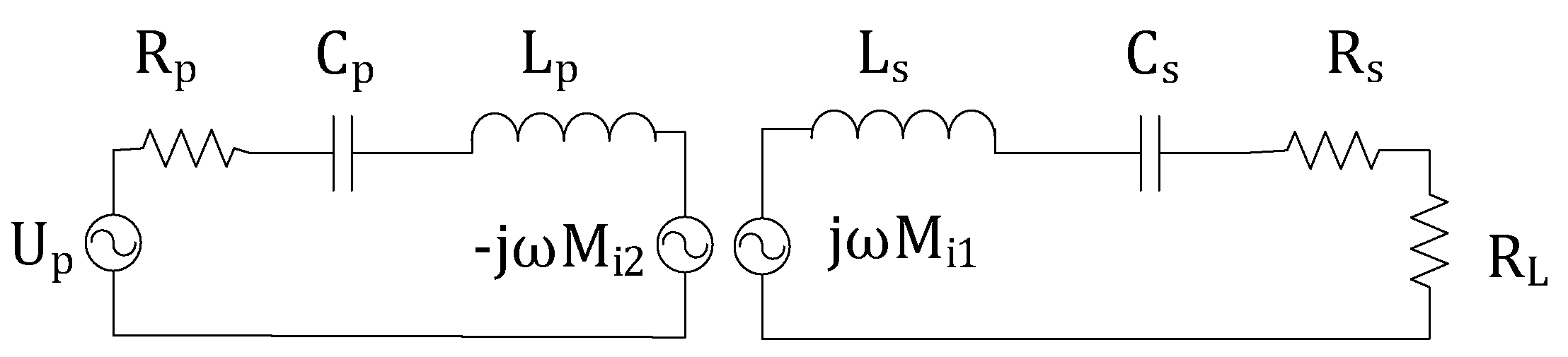
Because of the loose coupling and the high magnetic flux leakage between power side coil and load side coil, the power factor of basic induction is low. This drawback makes basic inductive coupling of wireless charging system not optional for electric vehicle application. In order to solve this problem, the resonant compensation method is introduced, which adds compensation capacitances to compensate the leakage flux [22,23,24,25,26,27]. In this paper, we use the two-side series resonant compensation topology, which is applicable to electric vehicle inductive coupled wireless charging system. The circuit model of the inductive coupled wireless charging system with two series compensation is shown in Figure 1.
The high-frequency inverter AC power supply RMS voltage is , is pure impedance load, and are self-inductance of the power supply side coil and the load side coil, respectively, and M is mutual inductance. The two coils have internal impedance, and is the sum of the impedance of the power supply side coil and the primary side cable, is the sum of the load side coil impedance and the load side cable impedance. and are the power supply side and the load side resonant compensation capacitance, respectively. The current of the primary side and the secondary side are and respectively.
Based on the equivalent circuit theory and Kirchhoff’s law of voltage, we can get the following Equation (1):
where is the angular frequency of the circuit and Z represents the total impedance of the circuit. Subscripts p and s mean the primary side and secondary side, respectively. When the capacitor resonates with self-inductance of the coil in the same circuit, the total impedance is:
It can be written in another form:
Thus, the resonant frequency can be obtained as:
The equivalent circuit transmission efficiency is obtained by Equation (5):
is the load resistance and is the current passing through the load. Combine Equations (1) and (5), equivalent circuit transmission efficiency can be written as:
where , is the operating frequency.
It can be seen in Equation (6) that the system efficiency is positively correlated with the operating frequency f, the mutual inductance M between the primary and secondary windings of the wireless charging system. Load impedance also affects results.
In the following, we will use the control variable method to analyze the relationship between the efficiency of the system and load impedance, and give the relative parameter in Table 1.
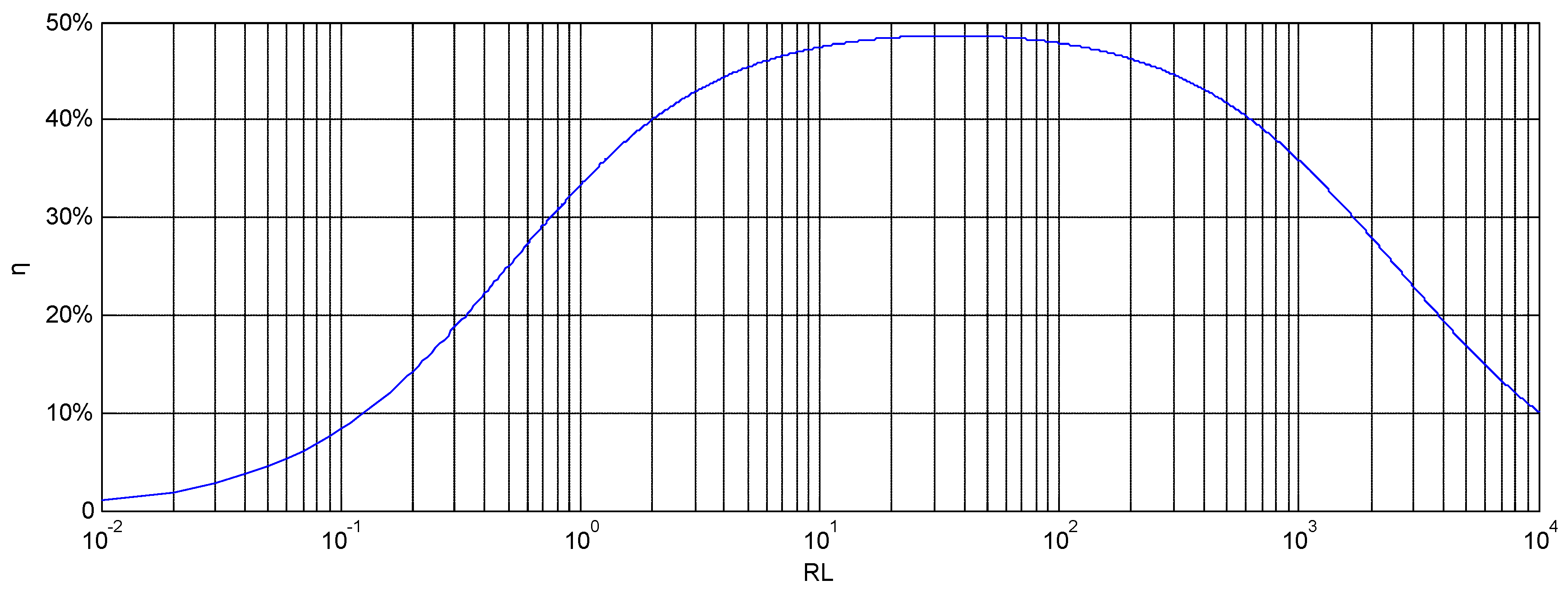
System efficiency versus load impedance curve is shown in Figure 2.
It can be seen from Figure 2 that the system efficiency is closely related to the value of load impedance [28,29]. As the load impedance increases, the efficiency of the system increases rapidly and then decreases slowly, which means there is an optimal value of load impedance, that is called matching impedance, with which the system can achieve the highest efficiency.
2.2. System Stability Analysis
If the load of the system changes, it may cause the frequency bifurcation phenomenon, which will result in multiple resonance points and decrease the stability of system output power [30,31,32,33]. Thus, it is necessary to study the relationship between the equivalent load and the frequency bifurcation boundary condition to guarantee the stability of the system.
The reflected impedance of the secondary side to the primary side is:
The symbol Re means the real part while Im represents the imaginary part. Primary side impedance is:
Normalize the primary input impedance:
where is the real part of the reflected impedance when the secondary side is resonant. Next, the imaginary part of the primary input impedance is normalized:
Normalization factor satisfies , the primary side quality factor is , the secondary side quality factor is , substitute them into Equation (11), obtaining that:
Let
To ensure is the only solution of , must be greater than zero, so its discriminant is less than zero, that is:
When the system satisfies the Equation (14), frequency bifurcation can be avoided. Moreover, the quality factor of the secondary border of the frequency bifurcation critical point is obtained as follows:
where the is the coupling coefficient and .
Based on the above discussion, it can be obtained that when , frequency bifurcation will not occur; when , frequency bifurcation will occur. Boundary load at frequency bifurcation is further obtained:
When frequency bifurcation will occur.
When frequency bifurcation will not occur.
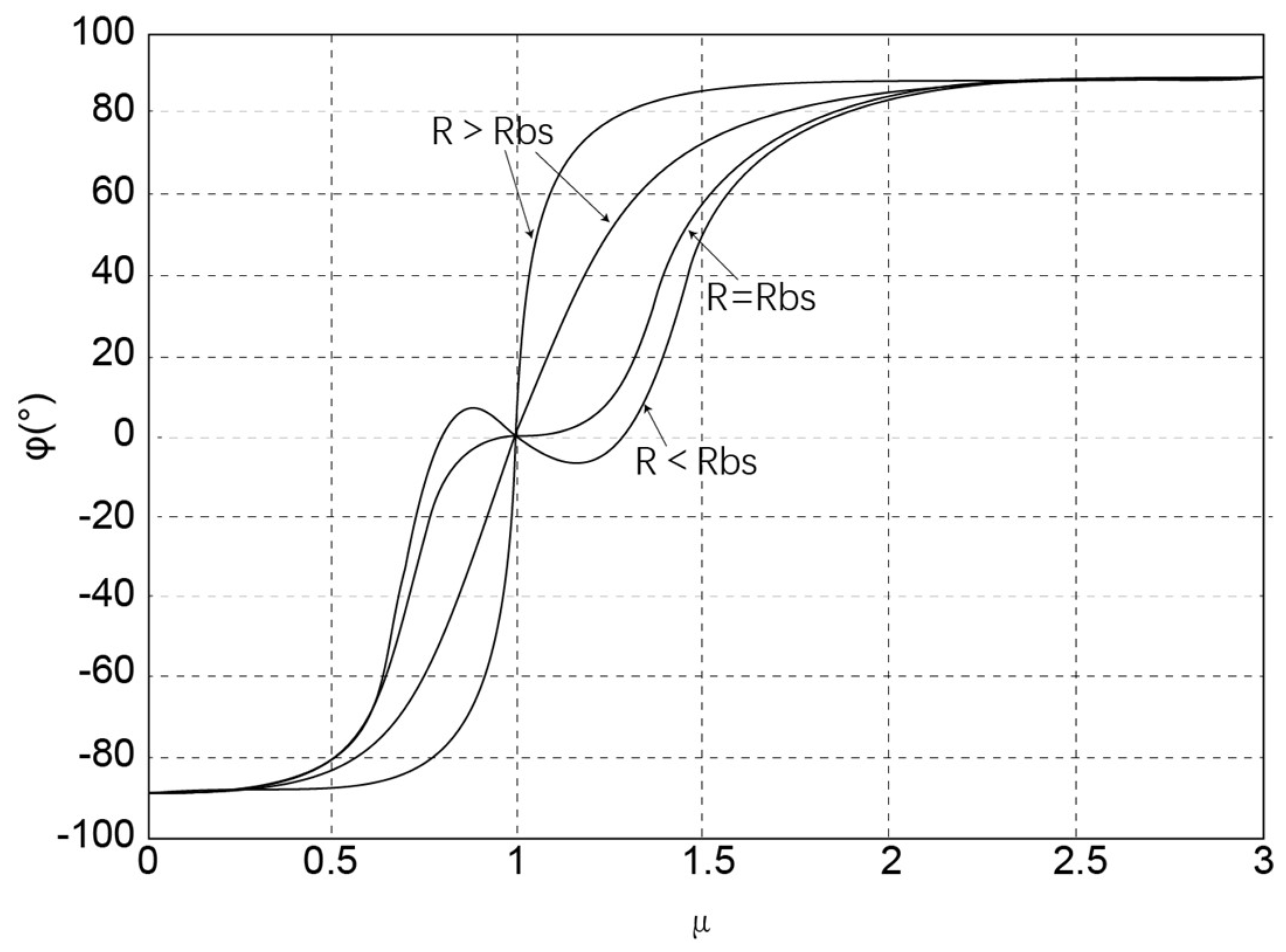
Figure 3 describes the relationship among the different equivalent R values, the impedance angle and the frequency. It can be seen from the Figure 3 that with the equivalent load surpasses , more than one points where the impedance angle of the system input is equal to zero appear which means the occurrence of frequency bifurcation phenomenon.
2.3. Resonant Frequency Identification Based on RMS Current of Inverter
The distance between the transmitter and receiver coil will change all the time in practical use of the wireless power transfer system, which will cause the change of system transmitter and receiver coil self-inductance when magnetic core is involved in the structure, and thus result in the drift of the system resonant frequency and detuned state of whole system. To address this problem, the system needs to be dynamically tuned in real time to improve transmission efficiency [34].
In the wireless charging system, the DC input power is inverted by the high-frequency inverter into plural power. represents DC input voltage while represents DC input current. The DC input power can be expressed as:
Plural power by the high-frequency inverter is:
where is the RMS current of primary coil, is phase difference between the high-frequency inverter output voltage and the primary coil current. When the power consumption of the high-frequency inverter is not considered, the average output power of the DC power supply is equal to the active power output by the high-frequency inverter, which is:
When the wireless charging system is resonant, the high frequency inverter circuit has the least energy requirement for the DC power supply. When only considering the RMS output of the high-frequency inverter device, the relationship between the output voltage of the high-frequency inverter device and the output voltage of the DC power supply can be obtained as follows:
From Equations (17)–(20), it can be derived that the relationship between the primary coil current RMS and DC input current is:
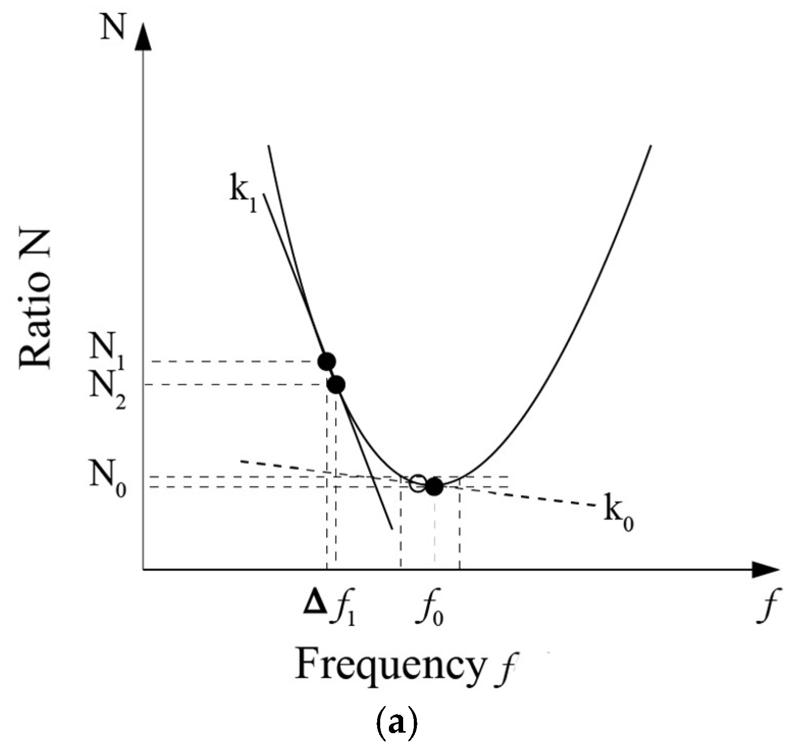
where N is the current ratio. When = 0, the current primary coil current and the DC output current ratio N is the least, and the inverter output voltage and the transmitter circuit current are in the same phase which means the wireless charging system at this time in a state of resonance. The relationship of current ratio N and the trend of the system operating frequency f is shown in Figure 4, is the system resonant frequency, the corresponding current ratio is the lowest ratio.
Through the value of k, we can determine the direction interval of the system frequency adjustment to approach the resonance state.
3. Load Adaptive and Frequency Control Strategy
A load adaptive circuit is designed for the purpose of controlling the equivalent impedance to keep the wireless charging system in the optimal impedance matching state. According to the actual situation of the wireless charging frequency bifurcation’s characteristic [18,20], the equivalent impedance should be kept above the critical value of the frequency bifurcation to avoid it. Moreover, a frequency tracking and regulation method is adopted to make the ratio of the primary coil current and the output current of the direct-current source smallest, which promises the wireless charging system a resonant state. Therefore, combining the load adaptive and frequency adjustment methods in the control strategy, a suitable wireless charging control strategy is put forward to keep the system tuning under all conditions to achieve high efficiency.
3.1. Hardware of Wireless Charging System Load Adaptive Control
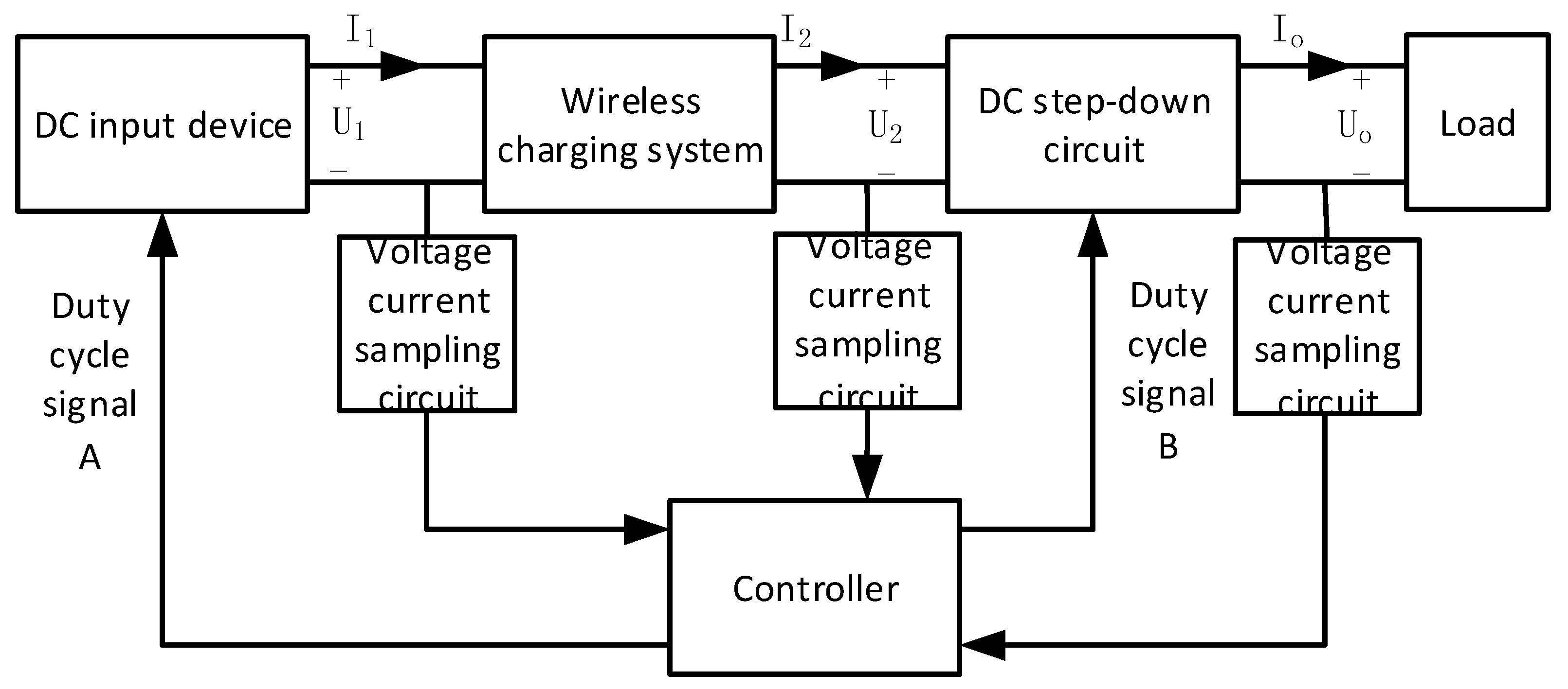
As shown in Figure 5, a wireless charging system includes a wireless charging device, an adjustable DC input device, a controllable DC buck circuit, and a controller. The value of the duty ratios of signal B and signal A of the DC input device are changed by the real-time DC buck circuit using the different characteristics of the voltage and current ratio (that is the equivalent impedance) of the front and rear ends of the DC buck circuit, so that the equivalent impedance, , of the energy transfer device is kept constant to make the wireless charging device working in the most efficient state.
At the same time, the power of the system changes in real time during wireless charging process. By adjusting the DC input device duty cycle signal A, the input voltage, , can be changed, and output voltage of the wireless charging device are changed indirectly to achieve real-time changes in charging power.
During the wireless charging process, the output voltage, , of the device is proportional to the input voltage, , of the DC input device, their relationship is , where the value of m is determined by the internal structure of the wireless charging device. The output voltage is then supplied to the DC buck circuit.
3.2. Load Adaptive Control Method for Wireless Charging System
The ideal DC buck circuit has equal power at both ends, and its output efficiency is less than 1 when taking the internal loss in the practical situation into consideration. Output voltage, , and output current, , are determined by load, which can be extracted from sampling circuit. Thus, it can be obtained:
The equivalent impedance, , is determined by the input current and input voltage of the DC input device:
Relationships between equivalent impedance and input voltage and output power can be obtained from Equation (26):
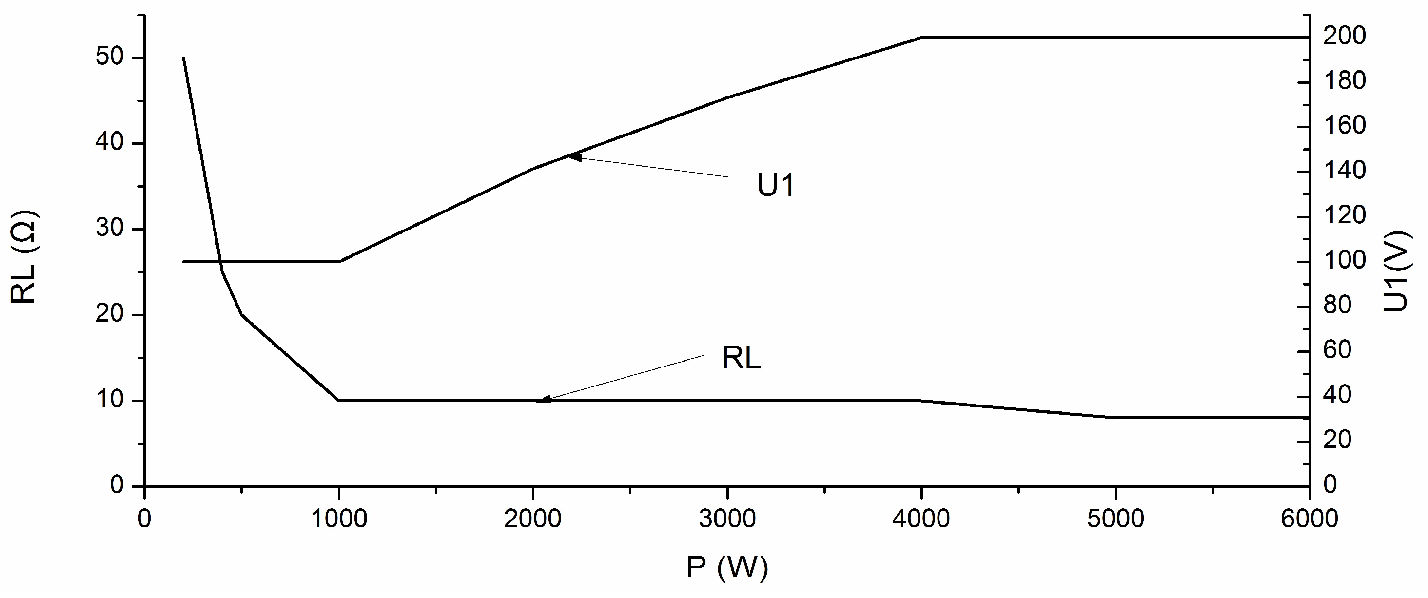
Therefore, in order to control the wireless charging device output equivalent load , DC input voltage should be increased when the output power becomes larger. But the DC input device has an input voltage range, that is, there is an upper limit of the input voltage beyond which improvement in the output power by means of increasing the input voltage is not allowed. In this situation, the output power can be improved only by adjusting the DC buck circuit to change the duty cycle signal B and reduce the equivalent load to the limit value . The whole control method is shown in Figure 6 and the maximum output power is:
If there is a lower limit of the input voltage, a lower output power can be obtained by adjusting the DC buck circuit to change the duty cycle signal B and increase the equivalent load.
In addition, if the design of charging device is unreasonable, and , the duty cycle signal, B, has to be changed by adjusting the DC buck circuit, to make the system work at the state of .
3.3. Frequency Adjustment Method Based on Inverter Current RMS Value
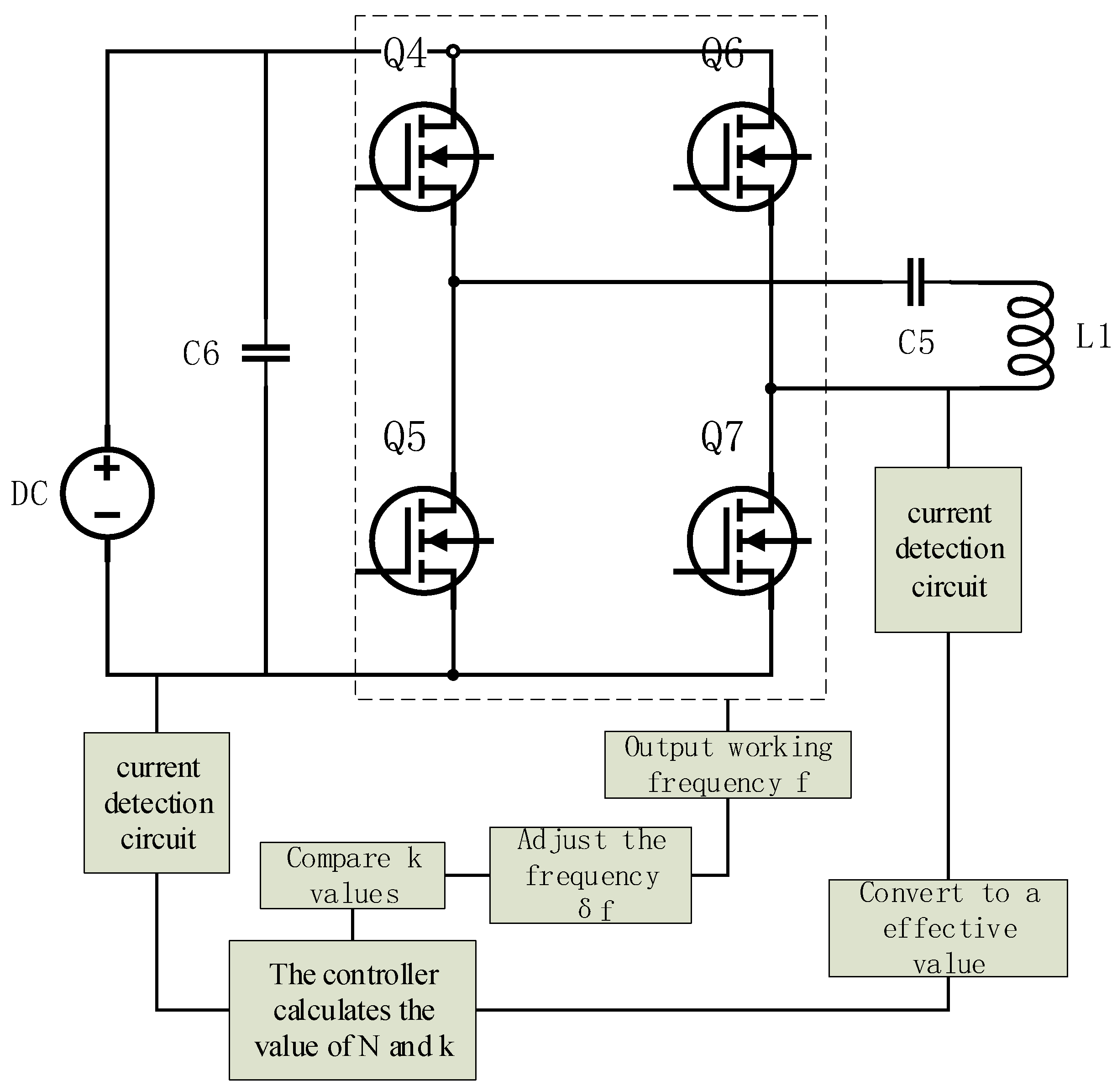
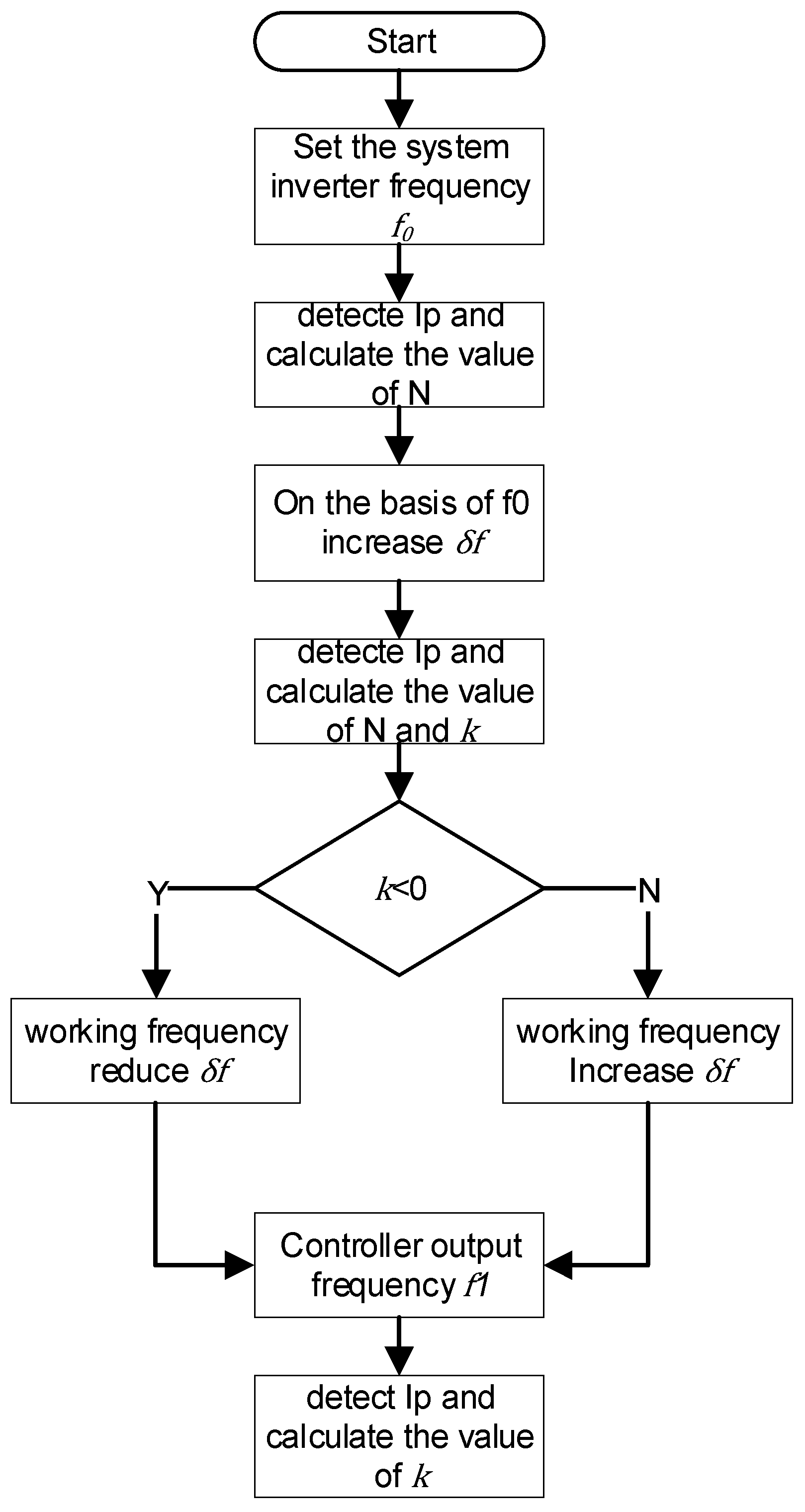
According to the analysis of the previous section, the characteristic of the wireless charging system resonance is that the ratio of the primary coil current, , and the DC source output current, , is the least. Based on this feature, the frequency tracking adjustment method is adopted to make the wireless charging system working at a resonant state. Wireless charging system frequency tracking structure is shown in Figure 7. In the experiment, the and are obtained through the hall current sensor to calculate N further in the controller. When the initial setting of the working frequency is , the high-frequency inverter controller calculates the corresponding value of N by firstly adjusting . The controller can calculate N after changing the frequency and calculate the value of k relatively. If k > 0, the system frequency is higher than the resonant frequency, needs decreasing; if k < 0, the system frequency is lower than the resonance frequency, the system will continue to increase . In addition, by judging the magnitude of k value, the current frequency can be judged how far away from the resonance frequency, and the step length is set as the ratio relation with k:
Based on the above steps, dynamic frequency adjustment can be achieved. When the value of k in the system is close to the zero-value range , the system will decrease to the minimum unit step to realize the fine-tune until the output N reaches the minimum (or k ≈ 0), which means the system reaches the resonant state. Specific implementations are shown in Figure 8.
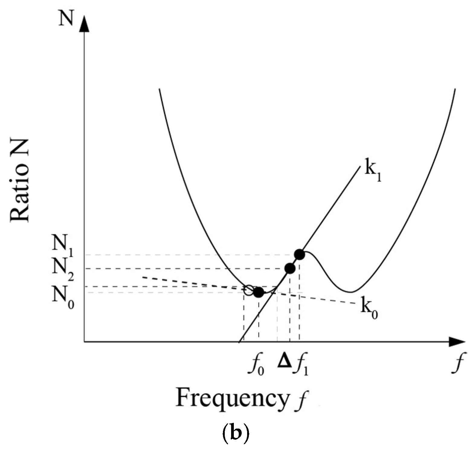
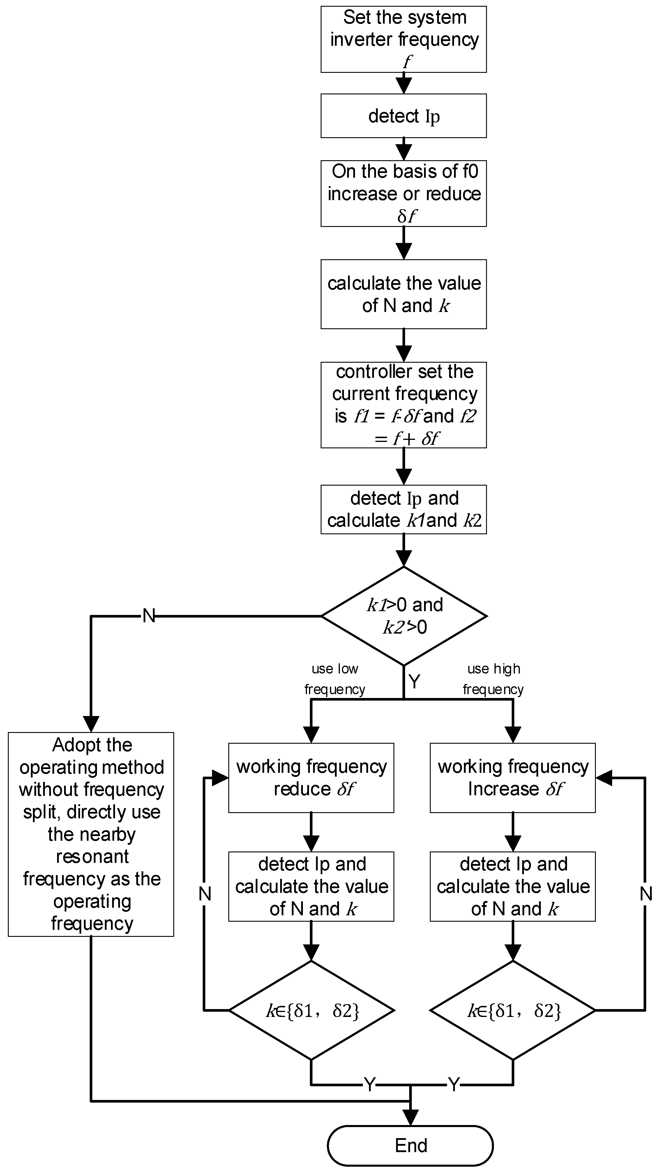
When the frequency bifurcation occurs, the system does not work in the best condition. At this time, based on the existing frequency f, set the operating frequency , , through the data returned by the current sensor to calculate the value of N and k to observe the trend. k1 and k2 can be calculated through Equation (22), When k1 > 0 and k2 < 0, the system is detuned at the original operating frequency and the system is judged to have frequency bifurcation at this moment. On the basis of this judgment, firstly, the high-frequency inverter controller increases the inverter’s operating frequency on the basis of f by rated adjustment amount, and then determines the value of k by the detected by the current detection circuit. When k enters the rated range , the system starts fine-tuning to make the derivative of k stable within the specified range. If the low-frequency control is utilized, f is reduced by rated adjustment. Through detected by the current detection circuit, when the k is in the rated range , the system starts fine-tuning, and it can achieve relative high efficiency at both frequencies. Specific implementations are shown in Figure 9.
3.4. Load Adaptive and Frequency Adjustment Control Strategy Simulation
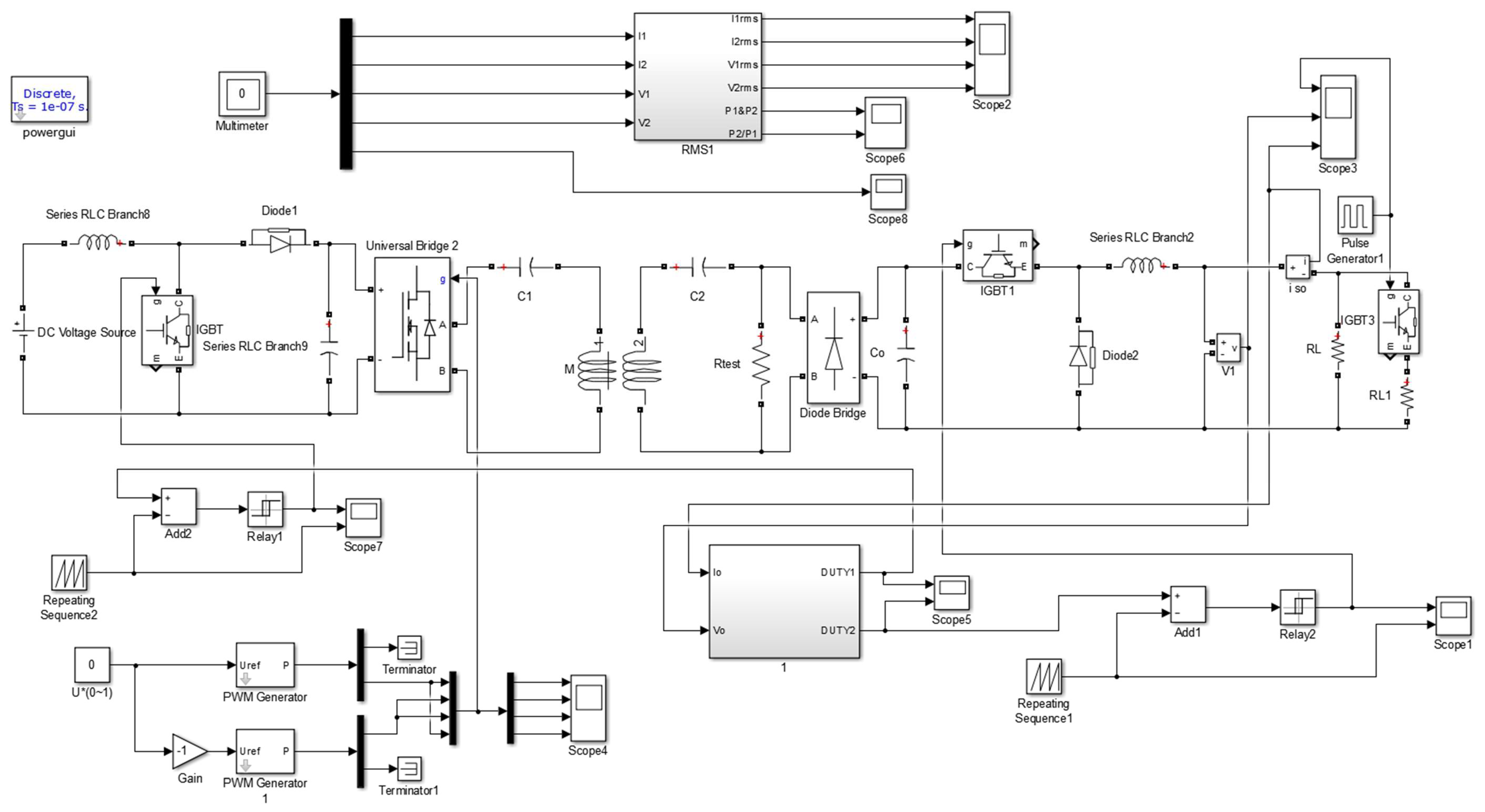
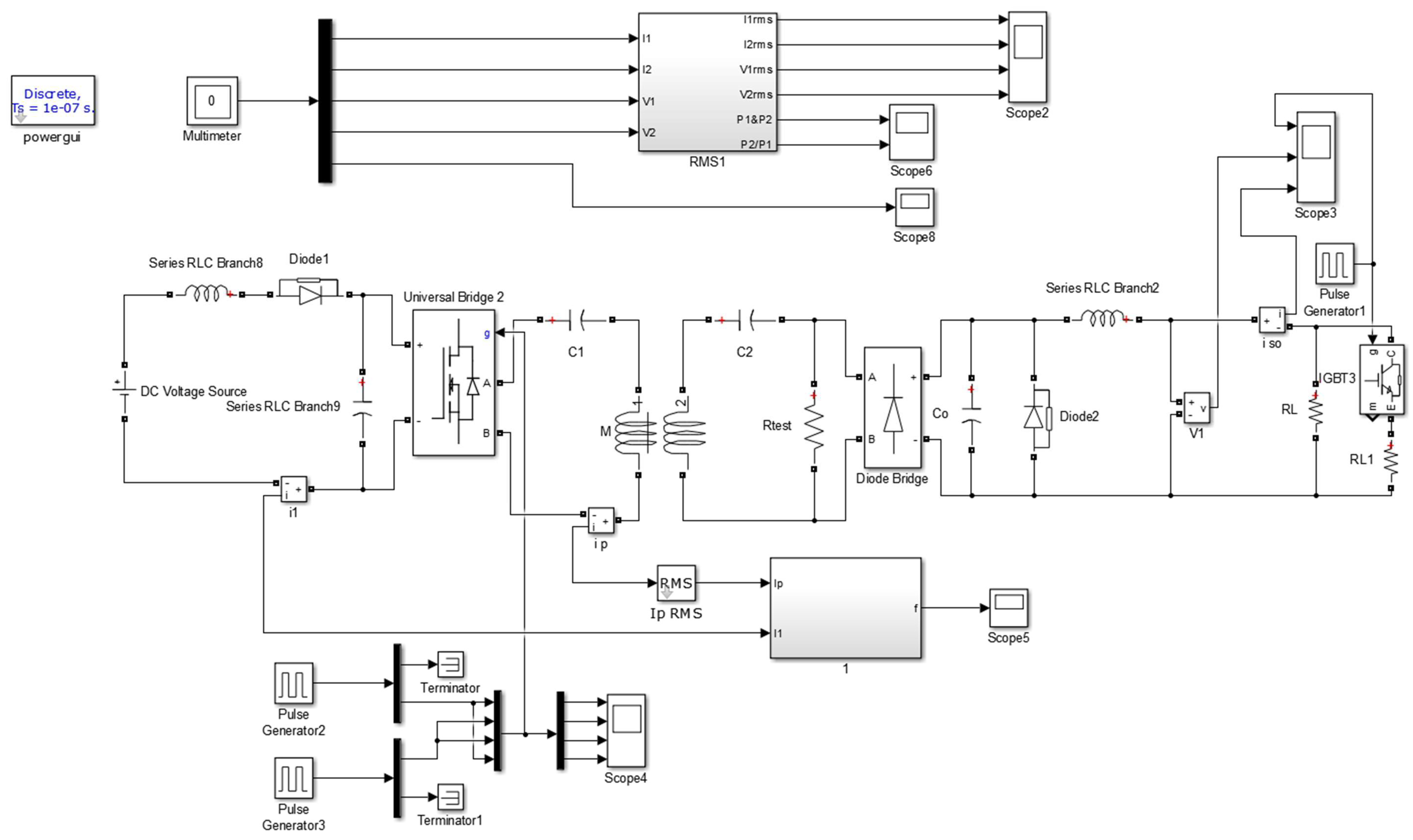
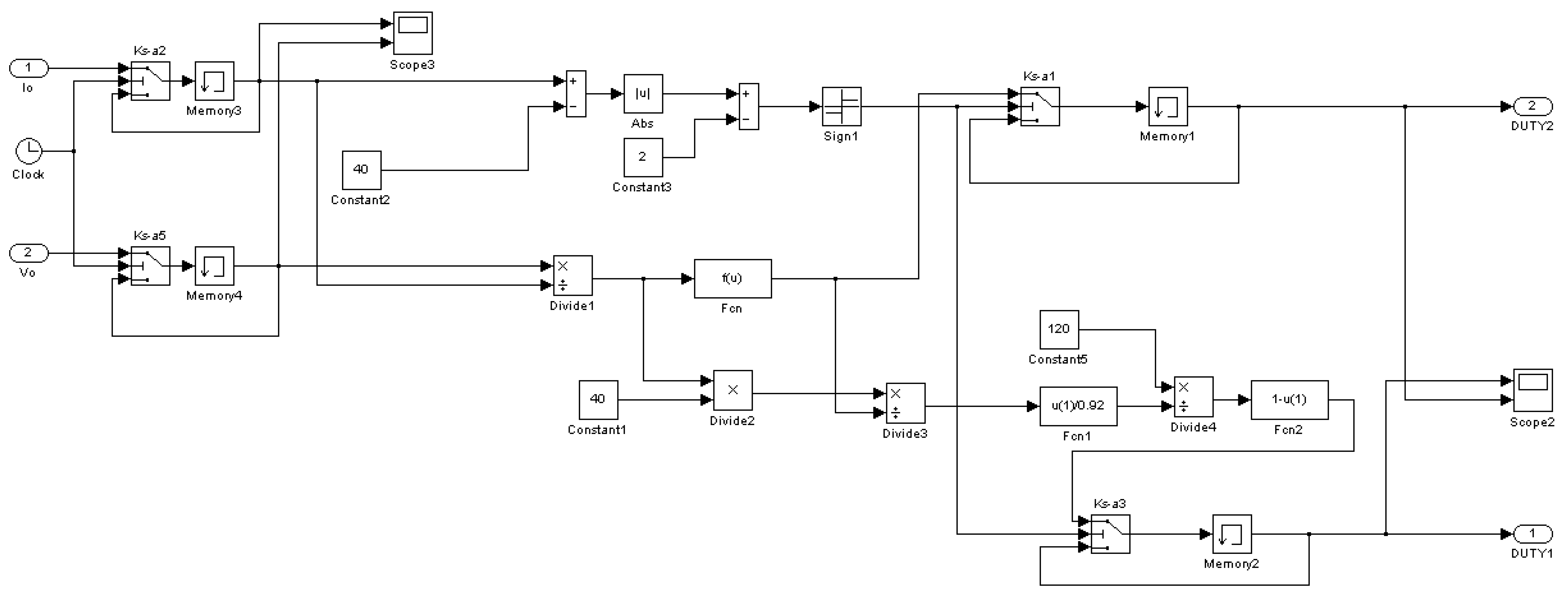
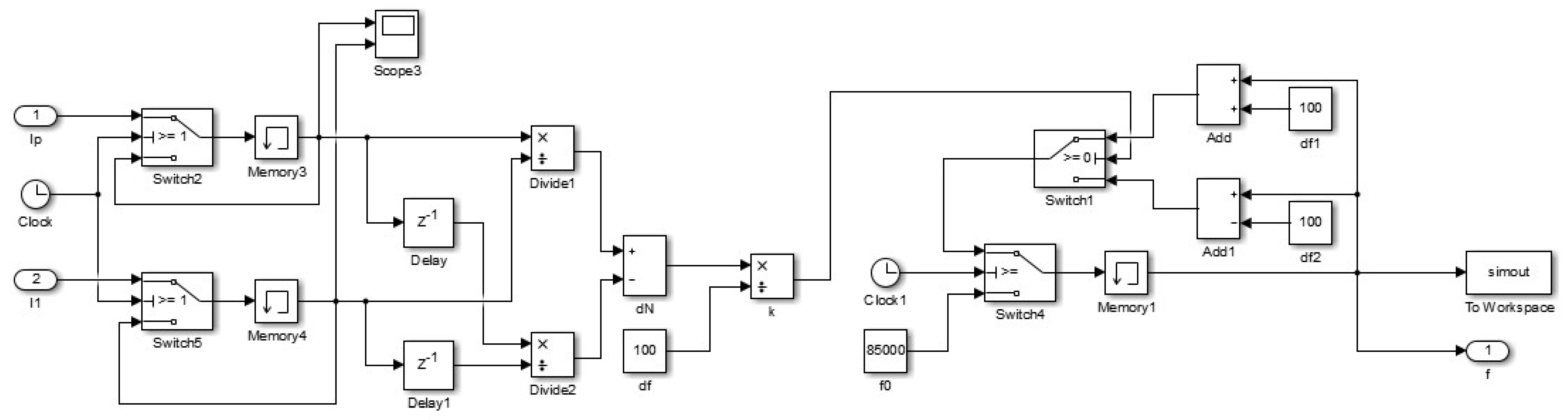
Figure 10 shows the circuit simulation diagram of the wireless charging system with a load adaptive control and frequency adjustment, respectively, of which the load is a battery with constant current and constant voltage control. A BOOST circuit is used as a current input device with adjustable output voltage, which is controlled by the duty cycle signal to supply the DC voltage required by the inverter circuit. The main circuit is described in the Section 2. And a BUCK circuit is used in the back-end as the buck circuit with controllable input signal, the circuit state can also be adjusted by the duty cycle signal. In a similar manner, Figure 11 shows the simulation circuit with a frequency adjustment control, which regulates the system working state by governing frequency instead of duty cycle signal. In addition, the controller is represented by an encapsulation with logic components inside. Figure 12 and Figure 13 are the internal logic components layout of the controllers, which shows the control flow of load adaptive matching control strategy and frequency adjustment, respectively.
4. Results of the Experiment
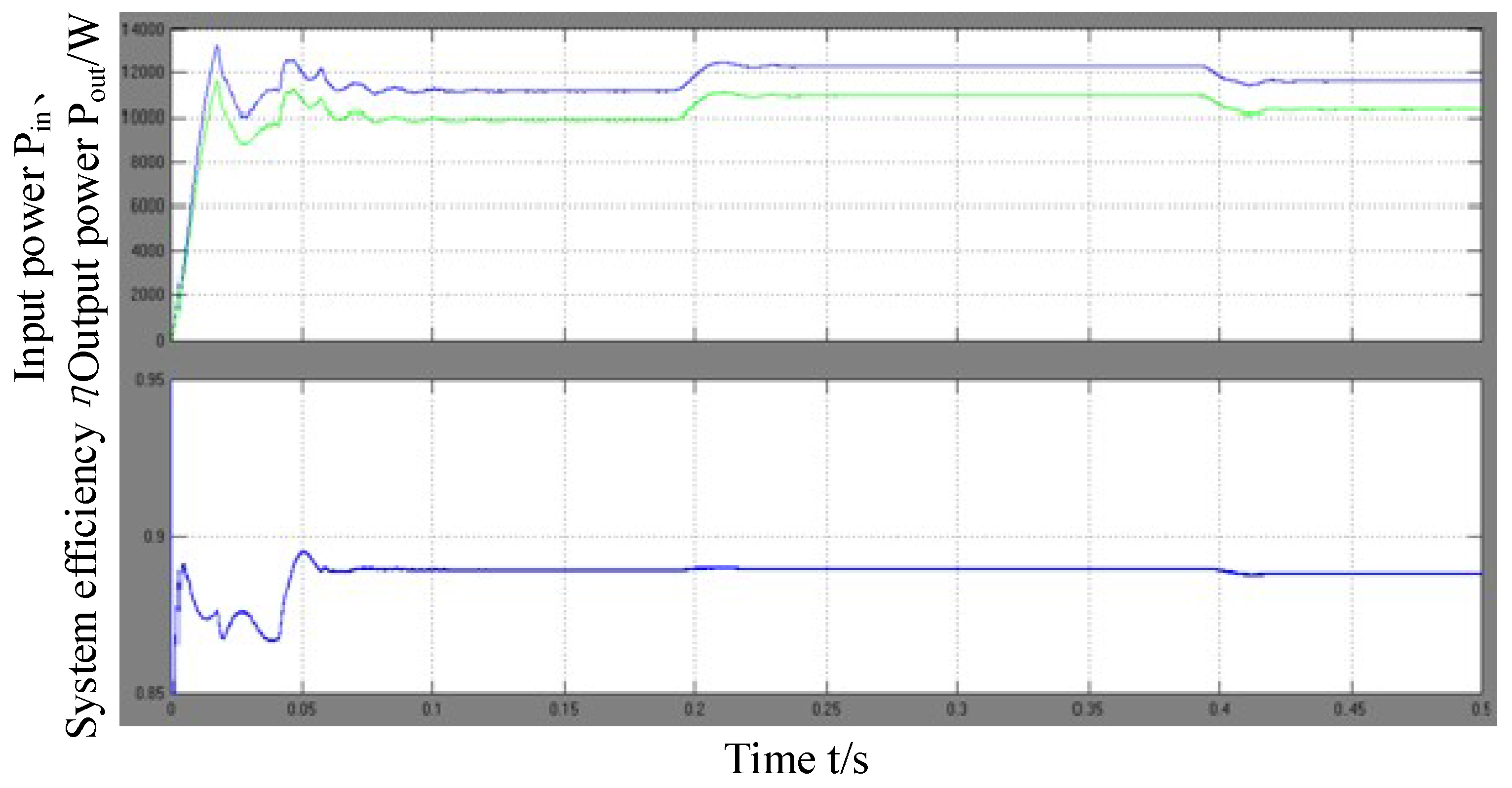
Figure 14 shows the power and efficiency experimental waveform of battery load constant current simulation, channel 1 is the power waveform, on which the higher one is the input power and the lower one is the output power. Channel 2 is the efficiency waveform. It can be seen that the circuit is still able to adapt to the change of power in the case of constant current charging of the battery, and can achieve constant current operation and keep the working efficiency optimal.
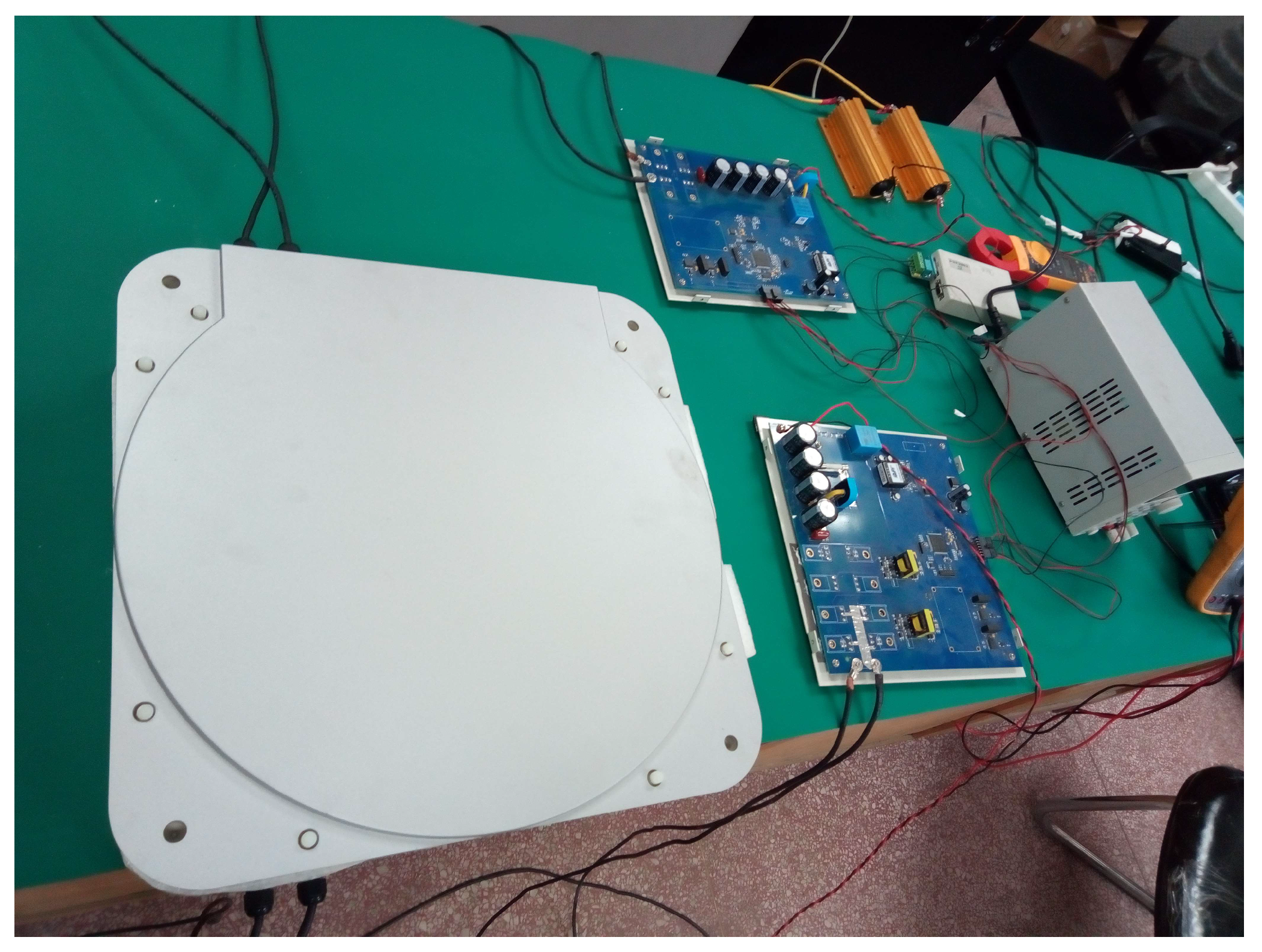
According to the theoretical calculation and simulation data, the load adaptive control system test platform of the conductive wireless charging system is constructed. The platform is shown in Figure 15.
Based on the platform, when the load of wireless charging system changes, the relationship between the workload and the system output is given as follows. When the load adaptive function is not used, the relationship between the system efficiency and load equivalent impedance is shown in Table 2. It is found that equivalent load has a direct effect on the efficiency of the system especially when the load impedance is less than 8 Ω, under this situation the frequency bifurcation occurs which reduces the efficiency greatly. Therefore, it is necessary to use load adaptive control method to improve the system efficiency and avoid the effect of the frequency bifurcation on the system efficiency when the equivalent load .
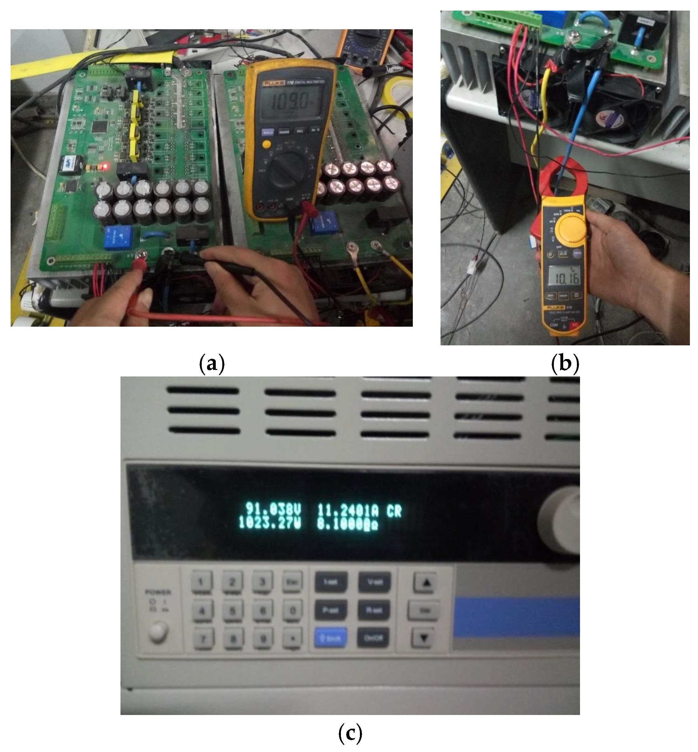
Switch on the load adaptive adjustment mode, adjust the load and test input and output current and voltage values, as shown in Figure 16. Experiment results show that system can achieve a good output under different load conditions, and the system efficiency is above 92%. The pictures of measuring process in shown in Figure 16.
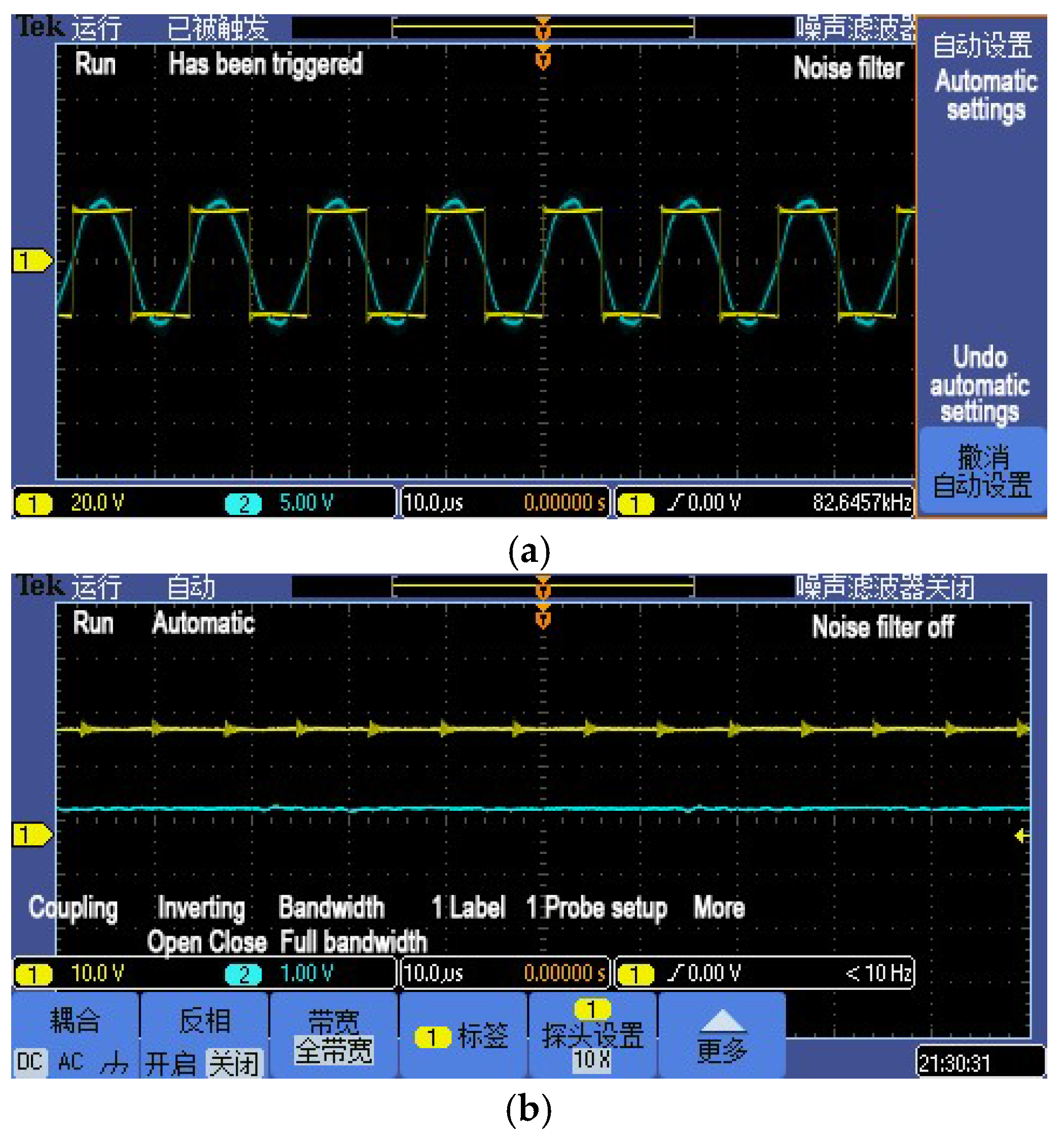
The test to check system performance with different coil distance is then carried out. DC power supply uses 100 V voltage output mode. At the beginning of the experiment, as shown in Figure 17, the wireless charging system is set to be resonant at a pitch of 10 cm and DC output current is 4.83 A.
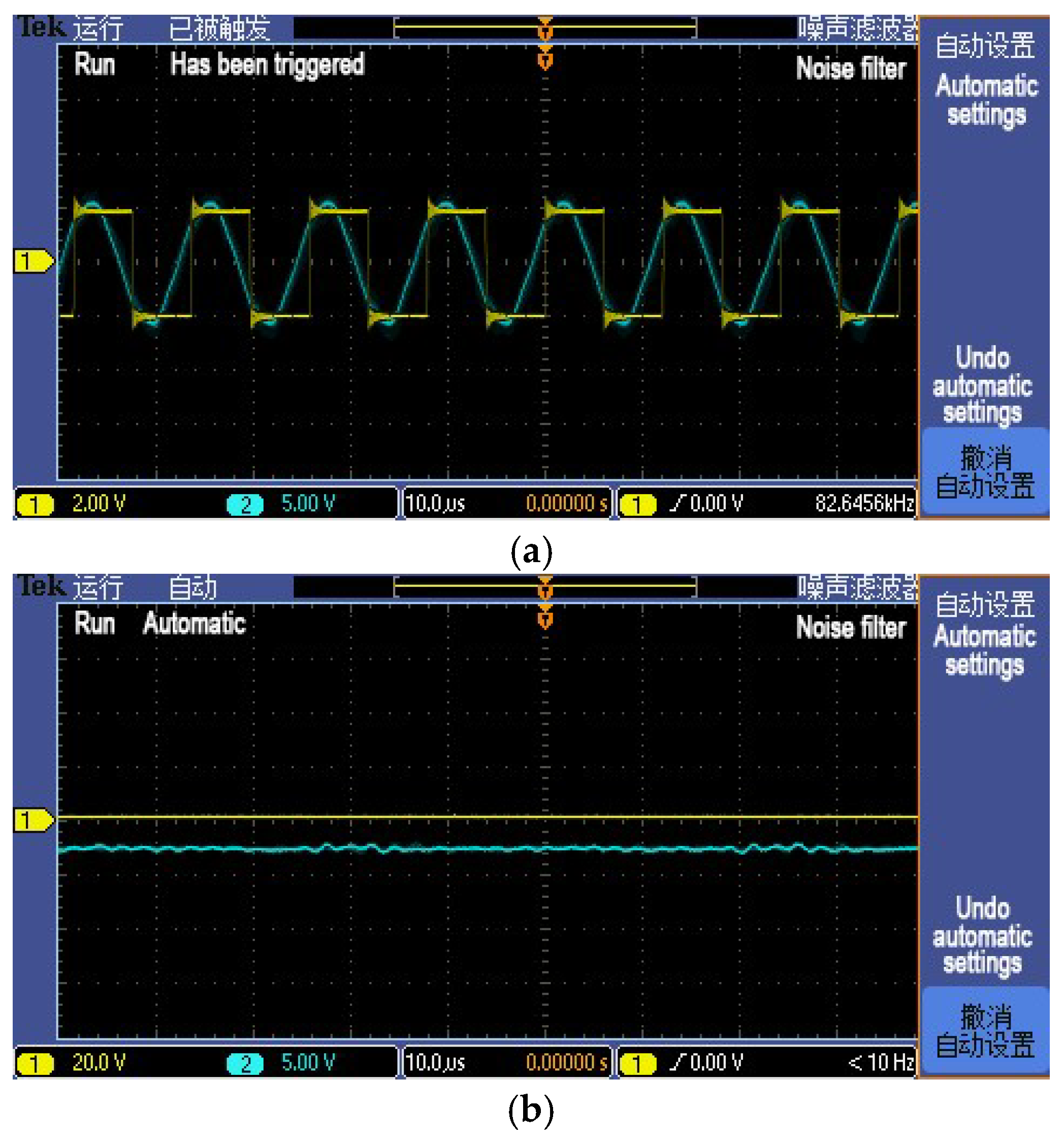
Later, the coil distance is adjusted to 12 cm, as shown in Figure 18, the wireless charging system is not resonant at this time and the current primary coil current and DC input current ratio N is 1.61.
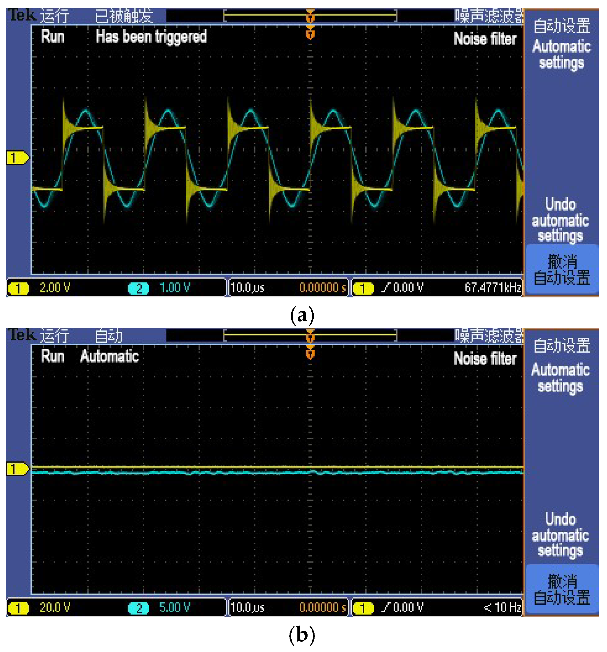
After dynamic tuning, the primary winding current and the DC input current ratio N achieves minimum value 1.1125, which means there is no phase difference between the high frequency inverter controller output square wave voltage and the sending coil current as shown in Figure 19. Wireless charging efficiency increases from 90.02% to 92.55%, which indicates the control strategy is effective.
The distance between the coils are increased from 10 cm to 12 cm gradually. The system efficiency is 92.88% at 10 cm, and it starts to decrease when the distance reaches 11 cm which is restored to 92.55% within 1 s automatically. Later, from 12 cm to 15 cm, the system works properly as expected, detailed testing data are listed in Table 3.
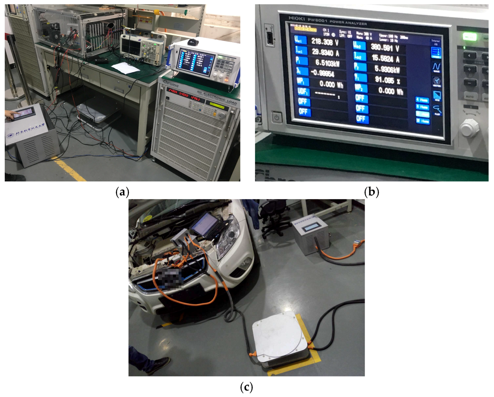
Lastly, as shown in Figure 20, high-power test and loading test are carried out. The efficiency of the overall system including the wireless charging system and the grid power supply module in the test under 6.6 kW high power condition is more than 91%, which can be even higher if the grid power supply module is not taken into consideration. In the loading test, the entire system worked normally and reached the expected level on the vehicle.
5. Conclusions
Based on the specific situation of electric vehicles, this paper establishes a wireless charging control strategy model suitable for vehicle battery system. A load-adaptive wireless charging method is designed according to the battery charging model and the relationship between the equivalent impedance and the system efficiency and the relationship between the equivalent impedance and the critical point of frequency bifurcation. Moreover, a method that determine the resonance state through the high-frequency inverter RMS current to is proposed based on the relationship between the system resonance and the primary coil RMS current, which has a faster response, wider scope of application and better environment adaptability than the previous researches. Afterwards, the model is established in MATLAB and verified by experiments. Conclusions are listed as below:
- (1)
- Considering the best equivalent load impedance and the boundary conditions of wireless charging frequency bifurcation, a control method is proposed to maintain a high system efficiency in real time. According to the constant current and constant voltage charging characteristics of power supply, wireless charging system and battery, a load adaptive wireless charging method suitable for vehicle battery is designed.
- (2)
- Based on the method of judging the resonance state of the system based on the high-frequency inverter RMS current in primary side, a rapid judgment and variable step length control method is proposed which can reduce the response time to less than 1 s. In addition, the control strategy under the frequency bifurcation caused by the close distance of the coil is put forward, of which the versatility is verified through experiments.
- (3)
- The control strategy model containing vehicle charging strategy, control method and mathematics model combines the load adaptive and frequency adjustment. The simulation results of the established model show that the strategy works perfectly and meets the design requirements.
- (4)
- The system model can be verified through independently designed wireless charging system to be effective under different load conditions and different distances. Finally, through high power test and loading test, the results show that the overall efficiency in 6.6 kW test can exceed 91%, which means that the designed wireless charging system control strategy achieves the desired purpose.
Author Contributions
X.Y. designed the algorithm and conducted the wireless charging experiments. He wrote the main parts of the manuscript. S.Y. and Z.P. checked the results and the whole manuscript. H.H. helped develop the Matlab code of the algorithm and wrote the corresponding part of the manuscript. P.Y. and H.C. conducted the wireless charging experiments and did some data analysis.
Acknowledgments
This work was supported by the key projects for new energy vehicles, national key research and development plan of China, under Grants 2017YFB0103200.
Conflicts of Interest
The authors declare no conflict of interest.
Abbreviation
| PSSS | Primary Series—Secondary Series |
References
- Zhen, N.L.; Chinga, R.A.; Tseng, R.; Lin, J. Design and Test of a High-Power High-Efficiency Loosely Coupled Planar Wireless Power Transfer System. IEEE Trans. Ind. Electron. 2009, 56, 1801–1812. [Google Scholar] [CrossRef]
- Sample, A.P.; Meyer, D.T.; Smith, J.R. Analysis, experimental results, and range adaptation of magnetically coupled resonators for wireless power transfer. IEEE Trans. Ind. Electron. 2011, 58, 544–554. [Google Scholar] [CrossRef]
- Cheon, S.; Kim, Y.H.; Kang, S.Y.; Lee, M.L.; Lee, J.-M.; Zyung, T. Circuit-Model-Based Analysis of a Wireless Energy-Transfer System via Coupled Magnetic Resonances. IEEE Trans. Ind. Electron. 2011, 58, 2906–2914. [Google Scholar] [CrossRef]
- Lyu, Y.; Meng, F.; Yang, G.; Che, B.-J.; Wu, Q.; Sun, L.; Erni, D.; Li, J.L.-W. A method of using nonidentical resonant coils for frequency splitting elimination in wireless power transfer. IEEE Trans. Power Electron. 2015, 30, 6097–6107. [Google Scholar] [CrossRef]
- Choi, B.H.; Lee, J.H. Design of Asymmetrical Relay Resonators for Maximum Efficiency of Wireless Power Transfer. Int. J. Antennas Propag. 2016, 2016. [Google Scholar] [CrossRef]
- Koizumi, M.; Komurasaki, K.; Mizuno, Y.; Arakawa, A. Wireless Power Feeding with Strongly Coupled Magnetic Resonance for a Flying Object. Wirel. Eng. Technol. 2012, 3, 86–89. [Google Scholar] [CrossRef]
- Kim, J.; Jeong, J. Range-Adaptive Wireless Power Transfer Using Multiloop and Tunable Matching Techniques. IEEE Trans. Ind. Electron. 2015, 62, 6233–6241. [Google Scholar] [CrossRef]
- Park, B.C.; Lee, J.H. Adaptive Impedance Matching of Wireless Power Transmission Using Multi-Loop Feed with Single Operating Frequency. IEEE Trans. Antennas Propag. 2014, 62, 2851–2856. [Google Scholar]
- Lim, Y.; Tang, H.; Lim, S.; Park, J. An adaptive impedance-matching network based on a novel capacitor matrix for wireless power transfer. IEEE Trans. Power Electron. 2014, 29, 4403–4413. [Google Scholar] [CrossRef]
- Namadmalan, A. Self-oscillating tuning loops for series resonant inductive power transfer systems. IEEE Trans. Power Electron. 2016, 31, 7320–7327. [Google Scholar] [CrossRef]
- Kim, N.Y.; Kim, K.Y.; Choi, J. Adaptive frequency with power-level tracking system for efficient magnetic resonance wireless power transfer. Electron. Lett. 2012, 48, 452–454. [Google Scholar] [CrossRef]
- Park, J.; Tak, Y.; Kim, Y.; Kim, Y.; Nam, S. Investigation of adaptive matching methods for near-field wireless power transfer. IEEE Trans. Antennas Propag. 2011, 59, 1769–1773. [Google Scholar] [CrossRef]
- Duong, T.P.; Lee, J.W. Experimental results of high-efficiency resonant coupling wireless power transfer using a variable coupling method. IEEE Microw. Wirel. Compon. Lett. 2011, 21, 442–444. [Google Scholar] [CrossRef]
- Luo, Y.; Yang, Y.; Chen, S.; Wen, X. A Frequency-Tracking and Impedance-Matching Combined System for Robust Wireless Power Transfer. Int. J. Antennas Propag. 2017, 2017. [Google Scholar] [CrossRef]
- Sun, Y.; Wang, Z.; Dai, X.; Su, Y.V.L. Study of frequency stability of contactless power transmission system. Trans. China Electrotech. Soc. 2005, 11, 56–59. [Google Scholar]
- Mai, R.; Lu, L.; Li, Y.; He, Z. Dynamic resonant compensation approach based on minimum voltage and maximum current tracking for IPT system. Trans. China Electrotech. Soc. 2015, 30, 32–38. [Google Scholar]
- Qiang, H.; Huang, X.L.; Tan, L.L.; Ji, Q.J.; Zhao, J.M. Achieving maximum power transfer of inductively coupled wireless power transfer system based on dynamic tuning control. Sci. China Technol. Sci. 2012, 42, 830–837. [Google Scholar] [CrossRef]
- Su, Y.; Tang, C.; Sun, Y.; Wang, Z. Load Adaptive Technology of Contactless Power Transfer System. Trans. China Electrotech. Soc. 2009, 24, 153–157. [Google Scholar]
- He, Z.; Li, Y.; Mai, R.; Li, Y. Dynamic compensation strategy of inductive power transfer system with inductive-resistive load. J. Southwest Jiaotong Univ. 2014, 49, 569–575. [Google Scholar]
- Dai, X.; Sun, Y. Study on Energy Injection Control Method for Inductive Power Transfer System. J. Univ. Electron. Sci. Technol. China 2011, 40, 69–72. [Google Scholar]
- Geng, Y.; Li, B.; Yang, Z.; Lin, F.; Sun, H.; Sun, H. A High Efficiency Charging Strategy for a Supercapacitor Using a Wireless Power Transfer System Based on Inductor/Capacitor/Capacitor (LCC) Compensation Topology. Energies 2017, 10, 135. [Google Scholar] [CrossRef]
- Yang, Q.; Xu, G.; Jin, J.; Geng, D.; Fu, W.; Yan, W.; Sun, M. Optimal design of energy transmission system for implantable device base on WiTricity. In Proceedings of the Digests of the 14th Biennial IEEE Conference on Electromagnetic Field Computation, Chicago, IL, USA, 9–12 May 2010. [Google Scholar]
- Wang, C.S.; Stielau, O.H.; Covic, G.A. Design considerations for a contactless electric vehicle battery charger. IEEE Trans. Ind. Electron. 2005, 52, 1308–1314. [Google Scholar] [CrossRef]
- Kasthuri, M.R.; Lekshmanan, M.N. Design and Control of a Transcutaneous Power Regulator for Artificial Heart. Int. J. Eng. Trends Technol. 2014, 8, 149–153. [Google Scholar] [CrossRef]
- Pantic, Z.; Bai, S.; Lukic, S.M. ZCS $LCC$-Compensated Resonant Inverter for Inductive-Power-Transfer Application. IEEE Trans. Ind. Electron. 2011, 58, 3500–3510. [Google Scholar] [CrossRef]
- Ravikiran, V. Review on Contactless Power Transfer for Electric Vehicle Charging. Energies 2017, 10, 636. [Google Scholar] [CrossRef]
- Wang, C.S.; Covic, G.; Stielau, O.H. Power Transfer Capability and Bifurcation Phenomena of Loosely Coupled Inductive Power Transfer Systems. IEEE Trans. Ind. Electron. 2004, 51, 148–157. [Google Scholar] [CrossRef]
- Duong, T.P.; Lee, J.W. A Dynamically Adaptable Impedance-Matching System for Midrange Wireless Power Transfer with Misalignment. Energies 2015, 8, 7593–7617. [Google Scholar] [CrossRef]
- Yamakawa, M.; Shimamura, K.; Komurasaki, K.; Koizumi, H. Demonstration of Automatic Impedance-Matching and Constant Power Feeding to and Electric Helicopter via Magnetic Resonance Coupling. Wirel. Eng. Technol. 2014, 5, 45–53. [Google Scholar] [CrossRef]
- Fu, W.; Zhang, B.; Qiu, D. Study on frequency-tracking wireless power transfer system by resonant coupling. In Proceedings of the 2009 IEEE 6th International Power Electronics and Motion Control Conference, Wuhan, China, 17–20 May 2009. [Google Scholar]
- Imura, T.; Hori, Y. Maximizing Air Gap and Efficiency of Magnetic Resonant Coupling for Wireless Power Transfer Using Equivalent Circuit and Neumann Formula. IEEE Trans. Ind. Electron. 2011, 58, 4746–4752. [Google Scholar] [CrossRef]
- Kato, M.; Imura, T.; Hori, Y. New characteristics analysis considering transmission distance and load variation in wireless power transfer via magnetic resonant coupling. In Proceedings of the 2012 IEEE 34th International Telecommunications Energy Conference (INTELEC), Scottsdale, AZ, USA, 30 September–4 October 2012. [Google Scholar]
- Moh, K.G.; Neri, F.; Moon, S.; Yeon, P.; Yu, J.; Cheon, Y.; Roh, Y.-S.; Ko, M.; Park, B.-H. 12.9 A fully integrated 6 W wireless power receiver operating at 6.78 MHz with magnetic resonance coupling. In Proceedings of the IEEE International Solid State Circuits Conference—(ISSCC), San Francisco, CA, USA, 22–26 February 2015. [Google Scholar]
- Hui, S.Y.R.; Zhong, W.; Lee, C.K. A Critical Review of Recent Progress in Mid-Range Wireless Power Transfer. IEEE Trans. Power Electron. 2014, 29, 4500–4511. [Google Scholar] [CrossRef] [Green Version]
Figure 1.
The circuit model of the inductive coupled wireless charging system with two series compensation.
Figure 1.
The circuit model of the inductive coupled wireless charging system with two series compensation.

Figure 2.
System efficiency versus load impedance curve.

Figure 3.
System impedance phase vs. equivalent load.

Figure 4.
Relationship between the current ratio N and the trend of system operating frequency f: (a) frequency adjust without frequency bifurcation and (b) frequency adjust with frequency bifurcation.
Figure 4.
Relationship between the current ratio N and the trend of system operating frequency f: (a) frequency adjust without frequency bifurcation and (b) frequency adjust with frequency bifurcation.


Figure 5.
Hardware schematic diagram of load adaptive control strategy.

Figure 6.
Control model of load adaptive control strategy.

Figure 7.
Resonant frequency adjustment structure diagram based on inverter current RMS.

Figure 8.
Resonant frequency control flow chart based on inverter current RMS.

Figure 9.
Resonance frequency adjustment control flow chart considering the frequency bifurcation.

Figure 10.
Simulation circuit of load adaptive control strategy.

Figure 11.
Simulation circuit of frequency adjustment method.

Figure 12.
Controller arrangement plan of load adaptive control strategy.

Figure 13.
Controller arrangement plan of load adjustment method.

Figure 14.
Power and efficiency waveform of constant current simulation of battery load.

Figure 15.
Platform of wireless power transfer system with load adaptive control.

Figure 16.
Picture of measuring data of wireless power transfer system with load adaptive control. (a) Input voltage; (b) input current; and (c) output voltage and current displayed on programmable load.
Figure 16.
Picture of measuring data of wireless power transfer system with load adaptive control. (a) Input voltage; (b) input current; and (c) output voltage and current displayed on programmable load.

Figure 17.
Sample value before and after the high-frequency inverter device under 10 cm distance. (a) High-frequency inverter output voltage and primary coil current under 10 cm distance and (b) DC power output current under 10 cm distance.
Figure 17.
Sample value before and after the high-frequency inverter device under 10 cm distance. (a) High-frequency inverter output voltage and primary coil current under 10 cm distance and (b) DC power output current under 10 cm distance.

Figure 18.
Sample value before and after the high-frequency inverter device under 12 cm distance without frequency adjustment. (a) High-frequency inverter device output voltage and primary coil current under 12 cm distance without frequency adjustment and (b) DC power output current under 12 cm distance without frequency adjustment.

Figure 19.
Sample value before and after the high-frequency inverter device under 12 cm distance with frequency adjustment. (a) high-frequency inverter device output voltage and primary coil current under 12 cm distance with frequency adjustment and (b) DC power output current under 12 cm distance with frequency adjustment.

Figure 20.
High-power test and loading test of wireless charging system. (a) High-power test environment; (b) test results; and (c) loading test process.
Figure 20.
High-power test and loading test of wireless charging system. (a) High-power test environment; (b) test results; and (c) loading test process.


Table 1.
Parameter table of system efficiency and load impedance analysis.
| Parameter | Rp,s (Ω) | M (μH) | F (kHz) |
|---|---|---|---|
| Value | 0.5 | 67 | 85 |
Table 2.
Load influence on system efficiency without load adaptive control.
| Load/Ω | Primary Side | Power/W | Secondary Side | Power/W | Efficiency | ||
|---|---|---|---|---|---|---|---|
| Voltage/V | Current/A | Voltage /V | Current/A | ||||
| 6 | 100 | 8.29 | 829 | 62.9 | 10.06 | 632.774 | 76.33% |
| 8 | 100 | 8.34 | 834 | 74.3 | 9.47 | 703.621 | 84.37% |
| 9.6 | 100 | 8.07 | 807 | 81 | 8.6 | 696.6 | 86.32% |
| 12 | 100 | 7.45 | 745 | 89 | 7.42 | 660.38 | 88.64% |
| 24 | 100 | 4.78 | 478 | 103.4 | 4.3 | 444.62 | 93.02% |
Table 3.
Frequency adjustment test results from 10 cm to 15 cm.
| Distance (cm) | Frequency (kHz) | Input Voltage (V) | Input Current (A) | Inverter RMS Current (A) | N | Output Voltage (V) | Output Current (A) | Efficiency (%) | Note |
|---|---|---|---|---|---|---|---|---|---|
| 10 | 86.35579 | 100.00 | 4.83 | 5.37 | 1.1118 | 94.00 | 4.74 | 92.28% | reference |
| 11 | 86.35579 | 100.00 | 2.25 | 4.20 | 1.8667 | 64.60 | 3.13 | 89.91% | before |
| 11 | 83.61204 | 100.00 | 4.75 | 5.28 | 1.1116 | 94.30 | 4.64 | 92.15% | after |
| 12 | 83.61204 | 100.00 | 1.84 | 4.00 | 2.1739 | 58.50 | 2.85 | 90.61% | before |
| 12 | 80.90615 | 100.00 | 4.80 | 5.34 | 1.1125 | 95.10 | 4.67 | 92.55% | after |
| 13 | 80.90615 | 100.00 | 4.80 | 5.50 | 1.1458 | 94.80 | 4.63 | 91.47% | before |
| 13 | 80.12821 | 100.00 | 4.73 | 5.26 | 1.1121 | 94.30 | 4.64 | 92.54% | after |
| 14 | 80.12821 | 100.00 | 4.44 | 5.70 | 1.2838 | 91.50 | 4.48 | 92.36% | before |
| 14 | 78.98894 | 100.00 | 4.86 | 5.40 | 1.1111 | 95.90 | 4.69 | 92.58% | after |
| 15 | 78.98894 | 100.00 | 5.00 | 5.80 | 1.1600 | 96.70 | 4.70 | 90.93% | before |
| 15 | 78.86435 | 100.00 | 5.05 | 5.70 | 1.1287 | 97.10 | 4.78 | 91.94% | after |
© 2018 by the authors. Licensee MDPI, Basel, Switzerland. This article is an open access article distributed under the terms and conditions of the Creative Commons Attribution (CC BY) license (http://creativecommons.org/licenses/by/4.0/).
Share and Cite
MDPI and ACS Style
Yang, S.; Yan, X.; He, H.; Yang, P.; Peng, Z.; Cui, H. Control Strategy for Vehicle Inductive Wireless Charging Based on Load Adaptive and Frequency Adjustment. Energies 2018, 11, 1222. https://doi.org/10.3390/en11051222
AMA Style
Yang S, Yan X, He H, Yang P, Peng Z, Cui H. Control Strategy for Vehicle Inductive Wireless Charging Based on Load Adaptive and Frequency Adjustment. Energies. 2018; 11(5):1222. https://doi.org/10.3390/en11051222
Chicago/Turabian StyleYang, Shichun, Xiaoyu Yan, Hong He, Peng Yang, Zhaoxia Peng, and Haigang Cui. 2018. "Control Strategy for Vehicle Inductive Wireless Charging Based on Load Adaptive and Frequency Adjustment" Energies 11, no. 5: 1222. https://doi.org/10.3390/en11051222
Note that from the first issue of 2016, this journal uses article numbers instead of page numbers. See further details here.