

Abstract
In this experiment we have first determined the focal length of an equiconvex lens. We have observed that a real image can be formed by the lens on the same side of the source if the source is sufficiently strong. This is due to the reflection from the concave surface of the lens. We have measured these image distances for different object distances. From these measurements, we have determined the refractive index of the lens as well as its radii of curvature. The relationship between the object and image distances in the reflection from the concave surface of a lens as formulated here, is similar to the ordinary reflection from a concave mirror. However, the focal length, in this case, turns out to be smaller than that of a regular concave mirror of the same radius of curvature by a factor of two, for a lens of refractive index of 1.5.
Export citation and abstract BibTeX RIS
1. Introduction
We have designed an experiment in which we determine the refractive index of the material of an equiconvex lens and the radii of curvature of its surfaces. In this determination, we do not need anything but a ruler for the measurement of distances and of course, an equiconvex lens and a source of light. In these pandemic times, when students are confined to their homes, this experiment could serve as an interesting assignment.
The students can determine the focal length of the equiconvex lens by measuring the object distance and the distance of the real image of the source on the other side of the lens. However, we need another independent measurement which would allow us to determine both the refractive index of the lens and the radii of curvature of the lens surfaces which we assume to be the same. An interesting observation is that, a real image formed by reflection from the concave surface of the lens is visible from the side of the source. The lens behaves as a concave mirror in this case.
We have used the torch of a cellphone as the source of light. The light being sufficiently strong in intensity, we are able to see this real image. The theoretical analysis to determine the position of the real image formed in this way, consists of three steps. The first is the formation of an image by refraction, at the first surface of the lens. The second step is the formation of an image by reflection from the concave surface of the lens, which behaves as a concave mirror. The image of the first stage acts as an object for the second step. Similarly, the image of the second step acts as the object for the third step. In this step the rays come out from within the lens and form a real image on the side of the source. The position of the real image can be determined by holding a screen. This whole exercise would be suitable for the students who have learnt how to determine the position of the image formed by a lens, by doing a step by step calculation.
2. Theory
Our sign convention [1–3] for distances is the same as that of the x axis of a right handed Cartesian coordinate system. Along the optic axis, distances towards the right of the lens are positive and those towards the left are negative. Our measurements are always from the centre of the lens which is assumed to be thin. We work in paraxial approximation. We use algebraic equations [1] for the relations between object and image distances in both refractions and reflections. These equations are valid for all situations with real or virtual objects and images.
When an image is formed by a convex lens, we have the algebraic relation [1]:
here u1 is the object distance and v1 is the image distance. f is the focal length of the lens. The radii of curvature of the refracting surfaces are r1 and  In figure 1 we show the image formation by the equiconvex lens where r1 is positive and r2 is negative. Refractive index of the lens medium is µ. From equation (1) we get:
By measuring the real image distance v1 for an object at a distance u1 on the other side of the lens, we determine the focal length f of the lens.
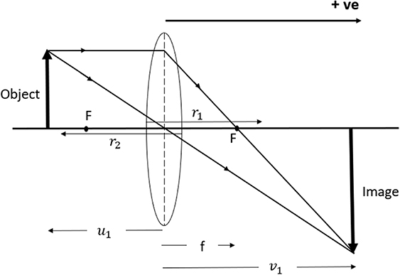
Figure 1. Image formation by the lens.
Download figure:
Standard image High-resolution imageFor the formation of the final real image reflected from the concave surface of the lens, we have three intermediate steps. See figure 2 for the ray diagram.

Figure 2. Image formation by the lens acting as a concave mirror.
Download figure:
Standard image High-resolution image(a) For refraction at the first convex surface,
Here u is the object distance and v2 is the distance of the image formed by refraction at the first surface r1. Equation (3) is the Gaussian formula for refraction at a single spherical surface [2] separating a medium of refractive index µ from air for which the refractive index is assumed to be 1. The image formed by this refraction serves as the object for reflection at r2. From equation (3) we get:
(b) In the second step reflection occurs at the concave surface of the lens. For this we use the equation for mirror reflection [1, 2]:
Equations (1), (3), and (5) are all algebraic where variables can be both positive or negative depending on the particular situation. In equation (5) v3 is the image position formed by reflection at r2. From this we get:
(c) In the third step we have refraction at the first surface. This is once again a Gaussian process of refraction at a single surface, but now from a medium of refractive index µ to air. For this process v3 acts as the virtual object and v is the final position of the image which is real. For this we apply the law of refraction at a curved surface from which we get:
By replacing v3 in equation (7) in terms of v3 given in equation (6), we get, after some algebra:
If our lens is equiconvex, on applying our sign convention we get,
Using equation (2) we replace  in equation (8) and get:
This equation is reminiscent of a mirror equation which the students are well acquainted with. However, the mirror is different here. A general formulation of the thick curved mirror has been developed in [4]. Our experiment with an equiconvex lens is a special case of this.
If we allow in equation (10), the object distance to be infinity, the image is formed by definition at the focus of the thick curved mirror the distance of which we denote by fm and get,
Now, equation (10) can be written as:
This is the new mirror reflection formula which is similar in form to the standard formula for a curved mirror. However, now the magnitude of the focal length:
where r is the magnitude of the radii of curvature for the two surfaces of the equiconvex lens. This can be easily shown from equation (11). This focal length is smaller than that of a concave mirror of the same radius of curvature by a factor of ( ).
).
In the case of reflection from the concave surface of the lens, u and v are both negative according to our sign convention. So equation (10) becomes:
where u and v are the magnitudes. We define:
and hence
With the sign convention chosen we get from equation (1):
3. Experiment
In figure 3 we show a photograph of our experimental setup. The distance from the lens to the cellphone torch is u and the distance from the lens to the white screen when the light is focused is v. In order to focus the light on to the white screen we had to tilt the principal axis of the lens away from the incoming light direction by a very small angle. The distances were measured by a 5 m tape measure.

Figure 3. A photograph of the experimental setup.
Download figure:
Standard image High-resolution image
In the first part of the experiment the focal length of the lens was determined in the standard way by noting the object distance u1 and the real image distance v1. The data are shown in table 1 where u1 and v1 are the magnitudes of the distances. In the case when the lens was being used as a concave mirror, the real image distance v was measured on the same side of the source, while the distance of the source was u. The data are shown in table 2 where u and v are only the magnitudes of the distances. In both the cases the image was observed on a thick sheet of white paper by focusing the light from the torch of a cellphone. With the values of u, v obtained from table 2 and the focal length of the lens, we determine x given by equation (15). From this we determine µ using equation (16). Finally, we determine the radii of curvature of the surfaces of the lens using equation (17).
Table 1. Data for the focal length f of the lens.
| u1 | v1 |

| Average f | |
|---|---|---|---|---|
| Obs. No. | cm | cm | cm | cm |
| 1 | 53.0 | 47.0 | 24.9 | |
| 2 | 50.0 | 48.5 | 24.6 | |
| 3 | 45.0 | 54.5 | 24.7 | 24.7 |
| 4 | 40.0 | 63.0 | 24.5 |
Table 2. Data for reflection from the concave surface.
| u | v | Average v | ||||
|---|---|---|---|---|---|---|
| Obs. No. | cm | cm | cm | x |

| Average µ |
| 1 | 13.0 | 11.5, 11.5, 11.5 | 11.5 | 4.05 | 1.49 | |
| 2 | 14.0 | 11.3, 11.1, 11.2 | 11.2 | 3.97 | 1.51 | |
| 3 | 15.0 | 10.7, 10.9, 10.8 | 10.8 | 3.93 | 1.52 | 1.50 |
| 4 | 20.0 | 9.1, 9.1, 9.2 | 9.13 | 3.94 | 1.52 | |
| 5 | 25.0 | 8.1, 8.2, 8.2 | 8.17 | 4.01 | 1.50 | |
| 6 | 30.0 | 7.7, 7.6, 7.4 | 7.57 | 4.09 | 1.48 |
In a related work [5] the focal length fm of the thick curved mirror has been determined from the known values of the refractive index and the radius of curvature of the surfaces of an equiconvex lens using the formulation developed in [4]. This focal length has been verified experimentally by the author of [5] by the method of autocollimation.
A more elaborate work has been done in [6] where the relation between the object and image distances in the thick curved mirror has been determined where the radii of curvature of the surfaces of the lens are different. However, the experimental method in this work is once again autocollimation.
Our work is different from both these works. We find the focal length of the thick curved mirror fm
by finding the image distances for different object distances using equation (12). We have checked that on placing the source at twice the focal distance from the thick mirror, the image is formed at the same position. However, our verification is not confined to the object distance  only.
only.
4. Results
With the sign convention chosen, focal length of the lens f is positive and the average turns out to be  cm. We have measured u1 and v1 with a tape whose least count was 0.1 cm. If we differentiate equation (1) with respect u1, we get:
Expressing v1 in this equation in terms of u1 and f from equation (1), we get:
Now the uncertainty in v1 can be written as:
When the object distance is close to the focal length, the denominator in the derivative term in equation (19) is small as u1 is negative and f positive. So the derivative term becomes large. Our estimate for the maximum error in v1 is about 3 mm assuming error in u1 as 1 mm.
From table 2 we have determined the average value of  . Finally, using equation (17), we get the radius of curvature as 24.7 cm for both the surfaces. From equation (11) we get the focal length for the mirror for reflection from the concave surface
  cm. Using u and v values shown in table 2, we can find fm
applying equation (12). The magnitude of fm
averaged over six sets of data, turns out to be 6.18 cm. This shows an overall consistency of our data.
cm. Using u and v values shown in table 2, we can find fm
applying equation (12). The magnitude of fm
averaged over six sets of data, turns out to be 6.18 cm. This shows an overall consistency of our data.
From equation (4) we calculate v2 for the object distance 30 cm. We have:
which leads to  cm. From equation (5) we get:
which leads to  cm. Thus, we find that both v2 and v3 are virtual positions, which behave as virtual objects for the next stages of image formation, steps 2 and 3 respectively. One can visualize the positions of these virtual objects from figure 2 where the virtual object sizes at v2 and v3 have been shown by dotted lines and both fall on the negative side.
5. Conclusions
We have observed that the concave surface of a lens can behave as a concave mirror and can form a real image on the side of a source of light if it is sufficiently strong in intensity. By noting the object and image positions for reflection from the concave surface of the lens, we have determined the focal length of the 'thick mirror'. Secondly, we have determined the focal length of the lens. From these two measurements, we have determined the refractive index of the material of the lens and the radii of curvature of its surfaces, which are assumed to be the same. When the lens is used as a concave mirror, its focal length is smaller than that of a regular concave mirror of the same radius of curvature by a factor of  , where µ is the refractive index of the lens material. Determination of the intermediate positions of the virtual images, serving as virtual objects for the next step, should be an instructive exercise for the students.
Acknowledgments
We thank Ranjan Maishal for bringing the interesting observation described in this paper to our notice. We also thank Prof. Subhash Chandra Samanta, under whose leadership the experiment was first performed at the Centre of Scientific Culture (CSC), Midnapore College.
Data availability statement
All data that support the findings of this study are included within the article.
Biographies

Soumen Sarkar is an assistant teacher in a high school in Hooghly district in West Bengal, India. He is a Master of Science degree holder in Physics from Vidyasagar University, West Bengal. He is interested in developing project ideas for students and performing new experiments in physics.

Surajit Chakrabarti is associated with Ramakrishna Mission Vidyamandira, Howrah district in West Bengal, India. He has a long experience in teaching Physics at the undergraduate level. He is a PhD in High Energy Experimental Physics from Tata Institute of Fundamental Research (TIFR), India. His passion is to develop teaching methodology which would enhance physical understanding of natural phenomena and to design novel experiments in physics.