Calculation of Safety Factors of the Eurocodes


1
Faculty of Built Environment, Tampere University, P.O. Box 600, FI-33014 Tampere, Finland
2
Computing Sciences, Faculty of Information Technology and Communication Sciences, Tampere University, P.O. Box 692, FI-33014 Tampere, Finland
*
Author to whom correspondence should be addressed.
Appl. Sci. 2021, 11(1), 208; https://doi.org/10.3390/app11010208
Submission received: 24 November 2020
/
Revised: 17 December 2020
/
Accepted: 23 December 2020
/
Published: 28 December 2020
(This article belongs to the Section Civil Engineering)
Abstract
:This study concerns the safety factor and the reliability calculation for structural codes. The Eurocodes are used as a reference. Safety factor calculation is a demanding task which necessitates using an appropriate root-solving algorithm with a sufficient numerical accuracy. This article introduces a simple algorithm to calculate the safety factors directly, as previously there has been no means to control the accuracy. Presently, the safety factors are defined indirectly through the reliability index. The basic safety factor calculation is presented here in six different equations with the same outcome but differences regarding the numerical calculation, which provides a method to check the accuracy and select a proper equation for the root solver. The safety factor calculation for the permanent and the variable load in the Eurocodes is based on the independent, i.e., random, load combination and single load pairs. The current approach of safety factor calculation applied in the Eurocodes is disclosed here. Simple analytical equations based on the convolution equation are presented. Those can be used instead of the computer programs applied currently.
1. Introduction
This study concerns safety factor calculation for structural codes. The Eurocodes [1] are used as a reference.
The structural codes and articles regarding codes are divided into three accuracy levels: I, II, and III [1,2,3,4,5]. The Eurocodes were earlier based on level I, i.e., on deterministic, historic, and empiric methods. However, the safety factors of the current Eurocodes are based on level II, i.e., on the first order reliability method. The primary assumption of this method is the independent load combination where a load reduction occurs. It is implemented by sensitivity factors αE and αR, which decrease the target reliability as in this load combination it is improbable that the highest permanent load and the highest variable load occur simultaneously. Also the Eurocodes include dependent load combinations. In the serviceability limit state (SLS), all loads are combined dependently, i.e., without a reduction factor, and in the ultimate limit state (ULS), permanent loads and multiple variable loads are combined dependently, too. The issue of the dependent load combination is not addressed in this article. The accuracy level III is a full probabilistic method. Such a method has not been implemented in any structural codes yet but was allowed for in [1].
The safety factors of the Eurocodes are defined currently by using the reliability index [1,2,3,4,5,6] as a reference. A safety factor set is selected, and the reliability index is calculated for each load case, which must match well enough with the target reliability. Such safety factor setting is difficult, and a program was developed recently to set the safety factors by minimizing the deviations of the actual reliability indexes from the target index [6]. In this article, a simple method for the safety factor calculation is presented. It offers a possibility to calculate the safety factors directly without using the reliability index as the reference. This article introduces the following three novel aspects for the safety factor calculation and setting:
- The equations offer direct calculation of the safety factors without using the reliability index as a reference. The annex C of [1] explains that the safety factors are set indirectly by using the reliability index as a reference.
- The equations can be used to calculate the reliability, or the safety factor in special cases like in cases with questionable resistance, proof loading, limited loading, and exceptional service time.
2. Materials and Methods
The assumptions, terms, and symbols of the Eurocodes [1] apply. The target one-year reliability index is β0 = 4.7, meaning that the 50-year reliability index is β50 ≈ 3.83 and the 50-year failure probability is Pf50 ≈ 1/15,400.
In the calculation algorithm explained here one value must be selected to associate all distributions, i.e., the permanent load, the variable load, and the material property, with the same value. In the Eurocodes, the characteristic values of the distributions, the mean of the permanent load, the 0.98 fractile of the one-year variable load, and the 0.05 fractile of the material property are the same. This value is here set to unity. Such selection is possible as all distributions can be multiplied by an arbitrary number and the calculation result remains unchanged. This value is called here a design point. This selection means that all materials have the same value i.e., unity, at the 0.05 fractile. Other material parameters, like means, are different as explained later. In this calculation, the design point is unity in the ULS, too, which means that the load distributions must be divided by the load factors and the material distribution must be multiplied by the material factors.
The permanent load distribution, cumulative distribution G(x,μG,σG), and density distribution g(x,μG,σG) are assumed to be normal, μG = 1, σG = 0.1, and VG = 0.1 [1,2,3,4,5]. The permanent load safety factor is γG = 1.35.
The variable load distribution, cumulative distribution G(x,μQ,σQ), and density distribution g(x,μG,σG) are assumed to be Gumbel distributions. The characteristic load is the 50-year return load, i.e., the one-year 0.98-fractile is set to the design point, μQ = 0.4909, σQ = 0.1964; VQ = 0.4. This distribution applies to the one-year loads. In the current Eurocodes, the variable load distribution corresponds to 5-year loads and distribution is
which is due to the reliability reduction by the sensitivity factor αE = 0.7. The variable load safety factor is γQ = 1.5.
The distribution of the material property is assumed to be log-normal. The 0.05 fractile is set at the design point. The safety factors are calculated for three materials with coefficients of variation: VM = 0.1, 0.2, 0.3, assumed to apply to steel, timber, and concrete. The parameters are given in Table 1.
The load ratio α and the variable load proportion in the total load is
3. Results
3.1. One Load
The general equation for the reliability calculation is [1,2,3,4,5,6,7,8,9,10,11,12,13]
where is the density distribution of the load, is the cumulative distribution of the material property, and is the failure probability. This equation can be written in an alternative form
where is the cumulative distribution of the load, and is the density distribution of the material property. The general design equation for a single load is
where is load factor, is load, is material property, and is material factor. This equation can be written in two different forms with the same result
and
These equations suggest that the reliability equation can be written in several forms. When the actual distributions are fixed in Equations (2) and (3), Equations (7)–(12) are obtained to calculate the reliability or the safety factors for the permanent load and the material property [7,8]:
and
The material factors for the variable load are calculated analogously, when the permanent load distribution is changed to the variable load distribution.
Analytically, these alternative equations all provide the same outcome. Numerically, some expressions are more suitable for the root solvers than the others, and the accuracy of the actual calculations depend, for example, on the integral bounds and the accuracy of the calculation device. In practice, cross-checking between two or more equations can be used to estimate and validate the numerical accuracy.
These equations disclose that the reliability calculation is arbitrary if the loads are multiplied or the material properties are divided by the load factors. It is also arbitrary if the material properties are divided or the loads are multiplied by the material factors. This means that the partial safety factor method and the allowable stress method yield the same design outcome regarding the reliability analysis. Material factors for the permanent load and for the 1-year and 5-year variable loads are given in Table 2.
3.2. Two Loads
The permanent load are combined independently using the convolution equation to obtain the cumulative distribution of the combination load (x) [7,8].
and
One equation applicable in calculating the combination load in load proportion α is
The failure probability or the safety factors are calculated independently in the combination load using Equations (7)–(17).
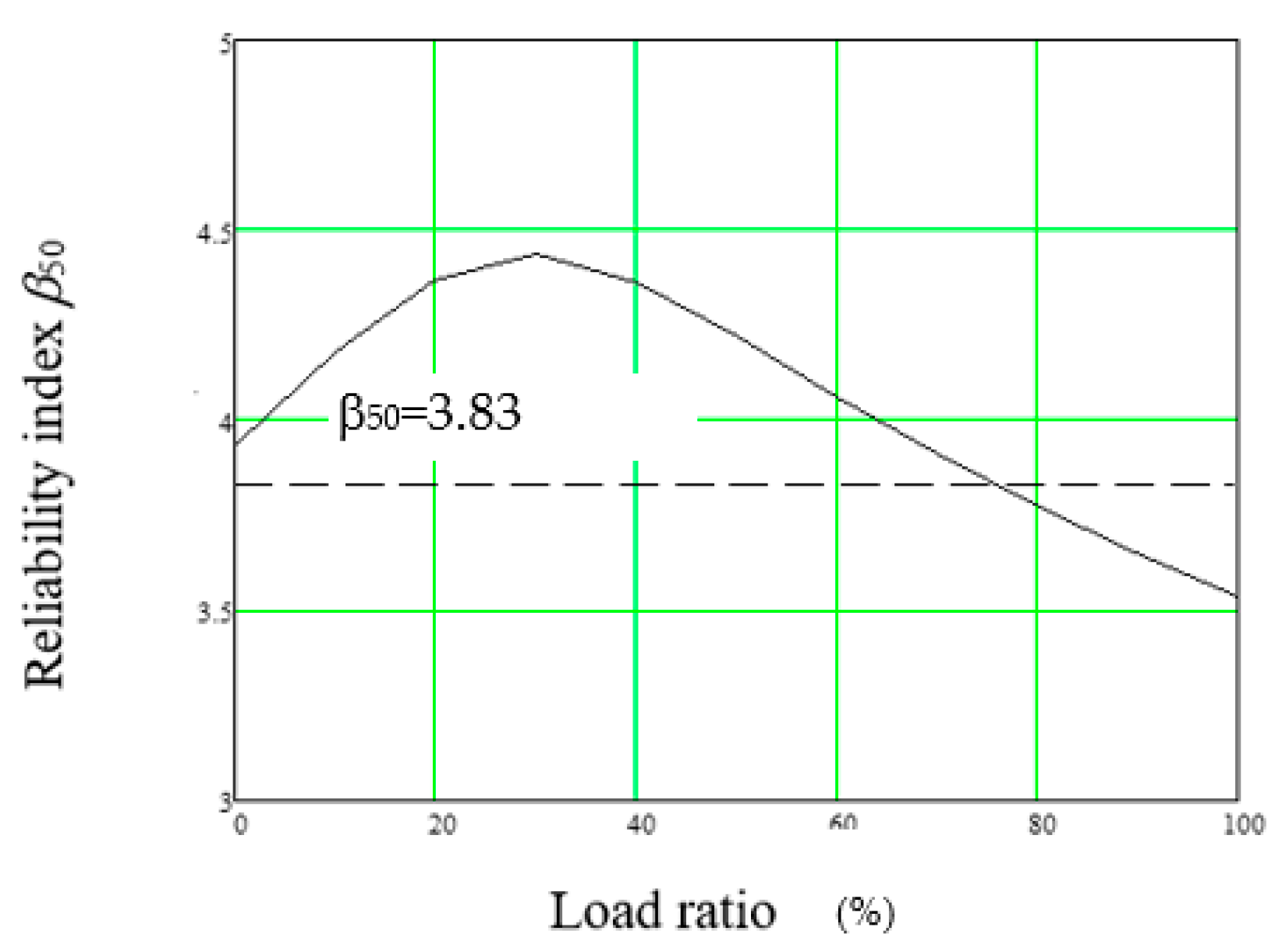
In Figure 3, the reliability index β50 for VM = 0.15, γM = 1.15 is given. The curve is presented in Figure 5 of [3] and the curves are the same within graphical and calculation accuracy, which means that the equations given above yield the same result as the current calculation algorithms.
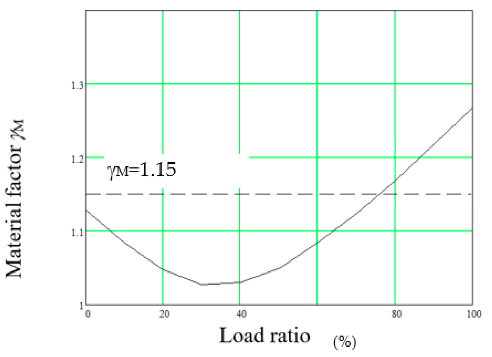
In Figure 4, a complementary calculation is given, i.e., the material safety factor is given as a function of the target reliability β50 = 3.83.
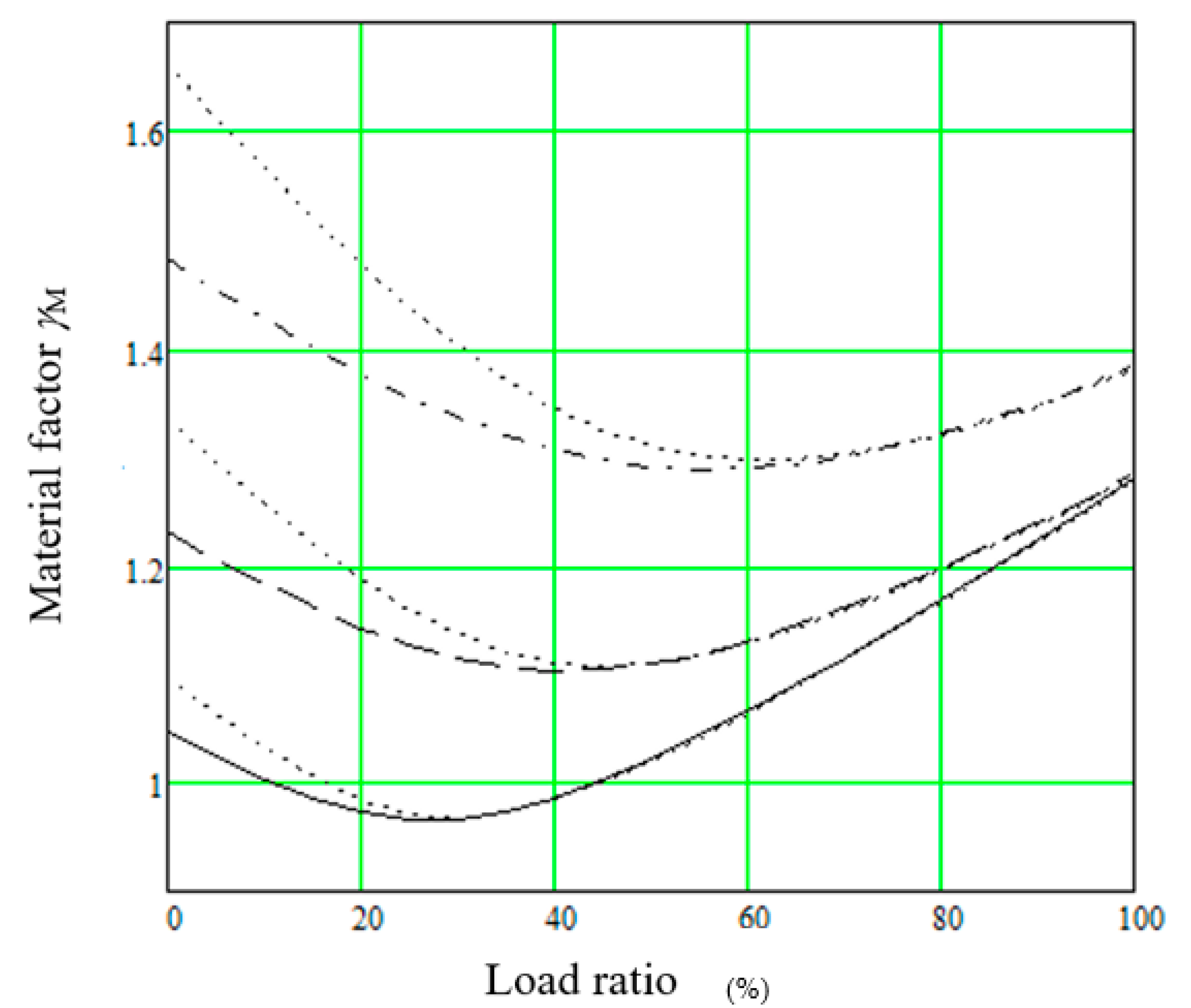
The equations above give the same result as given in [12]. In Figure 5, the material factors of the current Eurocodes are given using the combination rule (8.12) of the Eurocodes [1]. The curve for concrete matches well with the recommended value of safety factor γM = 1.4. The recommended value for timber γM = 1.3 looks high and the steel γM = 1.0, low for the loads where the variable load is dominating.
In some recent calculations [6], the reliability and the safety factors of the Eurocodes were calculated for one-year loads β1 = 4.7. Such calculation necessitates other sensitivity factors than disclosed in the Eurocodes (αE = 0.7). Here αE = 0.89, i.e., β1 = 4.2, is selected as it results in about the same outcome as presented above and the safety factors are given in dotted lines Figure 5.
When the material safety factor is used as a reference, both calculation methods lead to about the same outcome for variable loads, and the one-year calculation results in higher safety factors for the permanent loads.
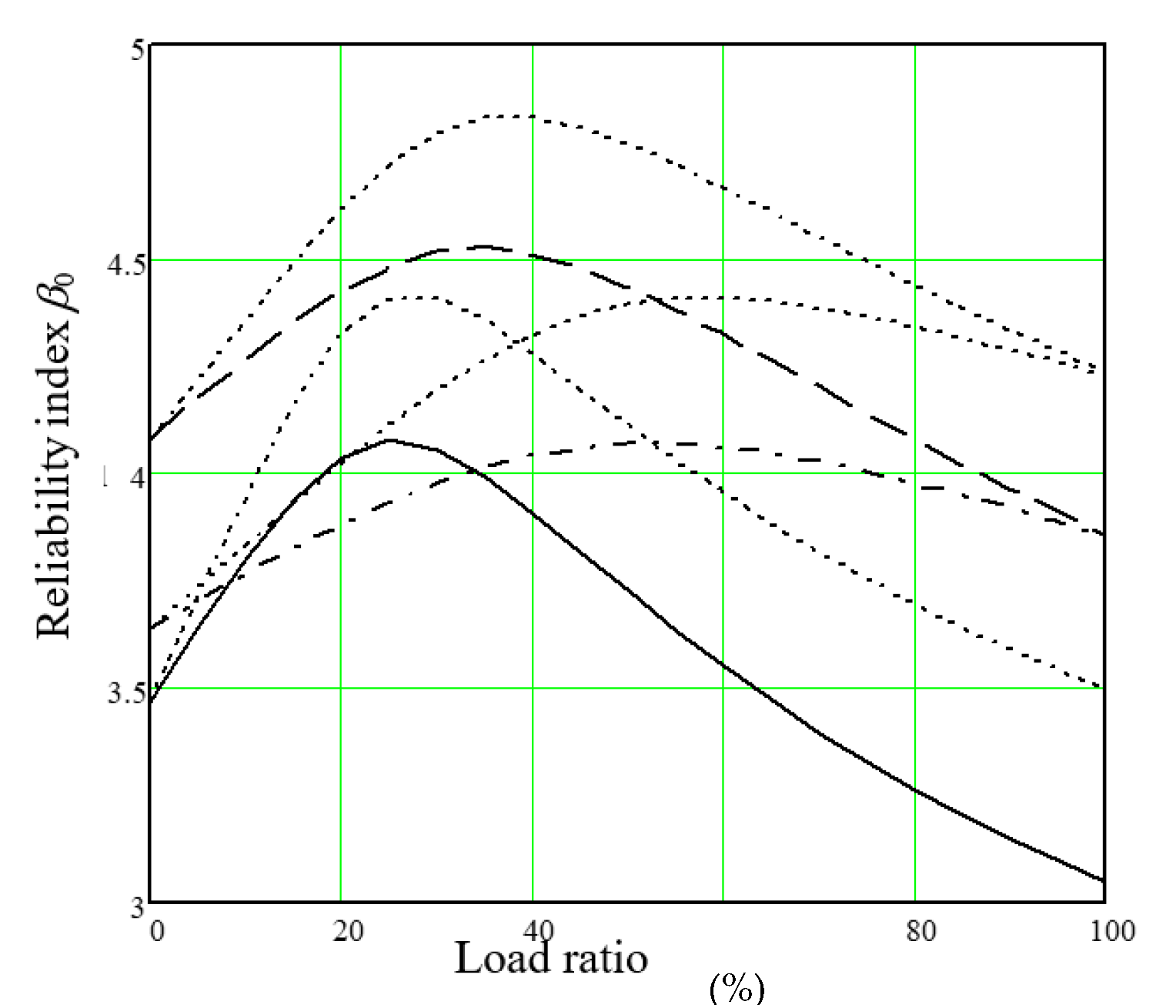
Figure 6 discloses the complementary calculation i.e., the reliability indexes are given as a function of the load ratio.
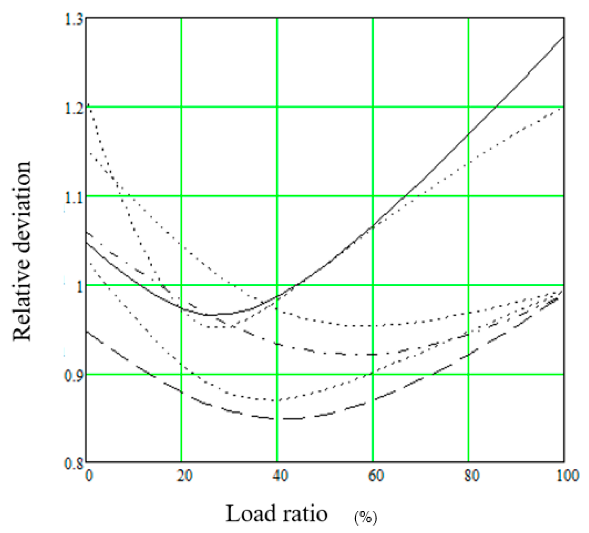
The current safety factor for steel is γM = 1. Figure 5 shows that the calculated value is 27% higher. However, Figure 6 shows that the reliability index for the current reliability calculation is 3.01 and for the one-year calculation 3.50, i.e., the relative deviations are 26% and 20%, respectively. Using the safety factor vs. the reliability index as the reference leads to a different outcome. In this case, the reliability index option results in a lower safety factor for the variable load. It is obvious that using the safety factor as the reference is more correct which confirms the earlier observation by the authors [7] that the reliability index is a biased abstraction, when it is used as the reference in the safety factor setting. The same is disclosed in Figure 7 where the relative deviation regarding the target is given for both calculations, i.e., there are cases where the safety factors are the same as shown in Figure 5, but the relative deviations are different.
4. Discussion
The calculations above are based on the dependent load combination (8.12) of [1]. In the independent load combination (8.13a,b), load reduction of approximately 10% occurs which means that the lines of Figure 5 lie about 10% higher when the load consists of equal permanent and the variable load, i.e., in this load combination, the lines are almost straight between the cases when the permanent load or the variable load is acting alone.
Using these equations, designers can verify existing partial safety factors or calculate new ones or calculate reliabilities accounting for the true distribution of properties. A need for such a calculation may occur in many special cases, e.g., the following ones:
- If the resistance of a structure is uncertain, and therefore, the structure is proof-loaded, the equations can be used to determine the required proof-load for the target reliability.
- In the current Eurocodes, the safety factors are set for 50-year loads. If the actual service time is different, the equations modify the safety factors.
- In case the resistance of a roof girder is uncertain, a feasible concept is to remove the snow load if it exceeds a critical value. The present equations can be applied to calculate this critical value.
5. Conclusions
The safety factor calculation presented can be performed in a simple manner. The calculation is based on analytic equations, requiring no special computer programs. The numerical accuracy of the safety factor calculation is a challenging task. The algorithm explained here is accurate, as such, and various alternative equations present an option for accuracy control. The reliability index is a biased abstraction used as the reference in the safety factor setting.
Author Contributions
Conceptualization, T.P. and T.L.; methodology, T.P.; software, T.P.; validation, T.P., S.P., and O.A.; formal analysis, T.P.; investigation, T.P.; data curation, T.P.; writing—original draft preparation, T.P. and J.M.; writing—review and editing, T.P., O.A., and J.M.; visualization, T.P. and O.A.; supervision, T.L.; project administration, T.P. All authors have read and agreed to the published version of the manuscript.
Funding
This research received no external funding.
Informed Consent Statement
Not applicable.
Data Availability Statement
Data is contained within the article. The data presented in the figures of this study can all be reproduced using the equations given in the study.
Acknowledgments
Keijo Ruohonen, Tampere University, collaborated for the mathematical formulation of this paper.
Conflicts of Interest
The authors declare no conflict of interest.
References
- CEN. Draft prEN 1990:2020 Eurocode—Basis of Structural Design; CEN: Brussels, Belgium, 2020. [Google Scholar]
- Gulvanessian, H.; Calgaro, J.-A.; Holicky, M. Designer’s Guide to EN 1990, EUROCODE: Basis of Structural Design; Thomas Telford Publishing: London, UK, 2002. [Google Scholar]
- Gulvanessian, H.; Holicky, M. Eurocodes: Using reliability analysis to combine action effects. Proc. Inst. Civ. Eng. Struct. Build. 2005, 158, 243–252. [Google Scholar] [CrossRef] [Green Version]
- Joint Committee on Structural Safety. Reliability-Based Code Calibration. Available online: http://www.jcss.byg.dtu.dk/codecal (accessed on 3 October 2020).
- JRC. Implementation of Eurocodes, Handbook 2, Reliability Backgrounds; JRC: Prague, Czech Republic, 2005; Available online: https://eurocodes.jrc.ec.europa.eu/showpublication.php?id=63 (accessed on 3 October 2020).
- Köhler, J.; Sørensen, J.D.; Baravalle, M. Calibration of existing semi-probabilistic design codes. In Proceedings of the 13th International Conference on Application of Statics and Probability in Civil Engineering, ICASP13, Seoul, Korea, 26–30 May 2019. [Google Scholar]
- Poutanen, T. Calculation of partial safety factors. In Applications of Statistics and Probability in Civil Engineering; Faber, M., Köhler, J., Nishijima, K., Eds.; Taylor and Francis Group: London, UK, 2011; pp. 303–304. [Google Scholar]
- Poutanen, T.; Pursiainen, S.; Mäkinen, J.; Länsivaara, T. Combination of permanent and variable loads. Raken. Mek. 2018, 51, 1–9. Available online: https://rakenteidenmekaniikka.journal.fi/article/view/65175/35889 (accessed on 3 October 2020). [CrossRef]
- Ferry Borges, J.; Castanheta, M. Structural Safety; Laboratorio Nacional de Engenharia Civil: Lisbon, Portugal, 1971. [Google Scholar]
- International Organization for Standardization. ISO 8930 General Principles of Reliability of Structures; International Organization for Standardization: Geneva, Switzerland, 1987. [Google Scholar]
- International Organization for Standardization. ISO 2394, General Principles of Reliability of Structures, List of Equivalent Terms; International Organization for Standardization: Geneva, Switzerland, 2015. [Google Scholar]
- Ranta-Maunus, A.; Fonselius, M.; Kurkela, J.; Toratti, T. Reliability Analysis of Timber Structures. VTT Research Notes 2109, Espoo 2001. Available online: https://www.vtt.fi/inf/pdf/tiedotteet/2001/T2109.pdf (accessed on 3 October 2020).
- CEN. EN 1992-1-1:2005, Eurocode 2. Design of Concrete Structures; CEN: Brussels, Belgium, 2005. [Google Scholar]
- CEN. EN 1993-1-1:2005, Eurocode 3. Design of Steel Structures; CEN: Brussels, Belgium, 2005. [Google Scholar]
- CEN. EN 1995-1-1:2004, Eurocode 5. Design of Timber Structures; CEN: Brussels, Belgium, 2004. [Google Scholar]
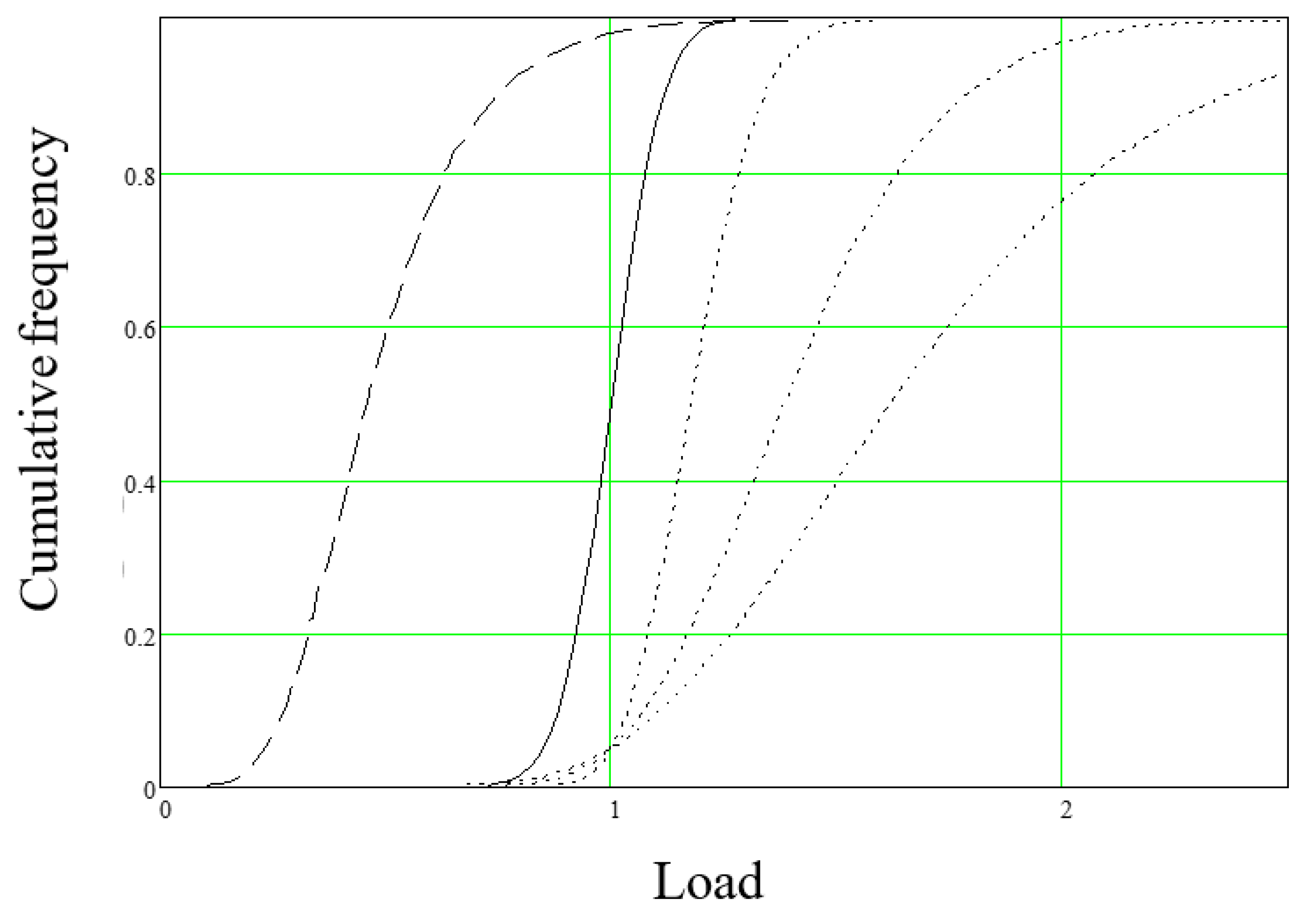
Figure 1.
The distributions in the serviceability limit state (SLS). Solid line, permanent load; dashed line, variable load; dotted lines, material property, steel, timber, and concrete.
Figure 1.
The distributions in the serviceability limit state (SLS). Solid line, permanent load; dashed line, variable load; dotted lines, material property, steel, timber, and concrete.

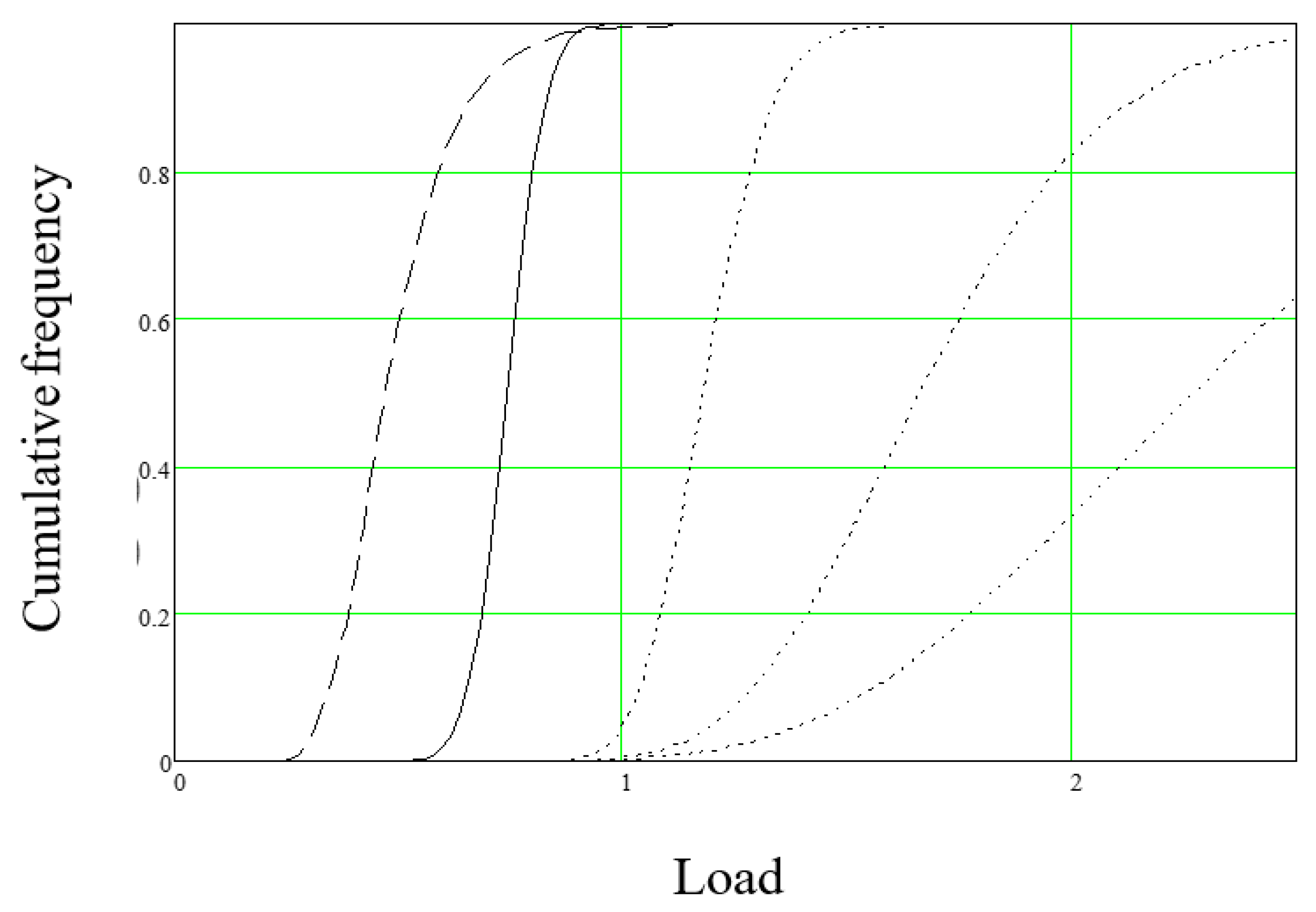
Figure 2.
The distributions in the ultimate limit state (ULS), solid line, permanent load, γG = 1.35; dashed line, variable load, γQ = 1.5; dotted lines, material property, steel, timber, and concrete, γM = 1.0, 1.3, 1.4 [13,14,15].

Figure 3.
The reliability index calculated for VM = 0.15, γM = 1.15. The horizontal dashed line denotes the target reliability index β50 = 3.83.
Figure 3.
The reliability index calculated for VM = 0.15, γM = 1.15. The horizontal dashed line denotes the target reliability index β50 = 3.83.

Figure 4.
The material factor calculated for VM = 0.15, β50 = 3.83. The horizontal dashed line denotes γM = 1.15.
Figure 4.
The material factor calculated for VM = 0.15, β50 = 3.83. The horizontal dashed line denotes γM = 1.15.

Figure 5.
Material factors γM of the current Eurocodes using the combination rule (8.12). Solid line, steel; dashed line, timber; and dash-dotted line, concrete. The dotted lines denote the safety factors of the one-year calculation.
Figure 5.
Material factors γM of the current Eurocodes using the combination rule (8.12). Solid line, steel; dashed line, timber; and dash-dotted line, concrete. The dotted lines denote the safety factors of the one-year calculation.

Figure 6.
Reliability indexes as a function of the load ratio. Solid line, steel, γM = 1.0; dashed line, γM = 1.3, timber; and dash-dotted line concrete, γM = 1.4. Dotted lines apply to the one-year calculation.
Figure 6.
Reliability indexes as a function of the load ratio. Solid line, steel, γM = 1.0; dashed line, γM = 1.3, timber; and dash-dotted line concrete, γM = 1.4. Dotted lines apply to the one-year calculation.

Figure 7.
Relative deviation of the calculated material factors and reliability indexes regarding the recommended values. Solid line, steel, γM = 1.0; dashed line, γM = 1.3, timber; and dash-dotted line concrete, γM = 1.4. The dotted lines display the corresponding deviations of the reliability indexes.


Table 1.
Parameters of the material properties.
| VM | μM | σM |
|---|---|---|
| 0.1 | 1.1841 | 0.1184 |
| 0.2 | 1.4125 | 0.2825 |
| 0.3 | 1.6921 | 0.5076 |
Table 2.
Material safety factors for single loads.
| VM | Permanent Load | Variable Load t = 1 Year | Variable Load t = 5 Years |
|---|---|---|---|
| 0.1 | 1.031 | 1.123 | 1.279 |
| 0.2 | 1.218 | 1.106 | 1.285 |
| 0.3 | 1.472 | 1.163 | 1.382 |
Publisher’s Note: MDPI stays neutral with regard to jurisdictional claims in published maps and institutional affiliations. |
© 2020 by the authors. Licensee MDPI, Basel, Switzerland. This article is an open access article distributed under the terms and conditions of the Creative Commons Attribution (CC BY) license (http://creativecommons.org/licenses/by/4.0/).
Share and Cite
MDPI and ACS Style
Poutanen, T.; Länsivaara, T.; Pursiainen, S.; Mäkinen, J.; Asp, O. Calculation of Safety Factors of the Eurocodes. Appl. Sci. 2021, 11, 208. https://doi.org/10.3390/app11010208
AMA Style
Poutanen T, Länsivaara T, Pursiainen S, Mäkinen J, Asp O. Calculation of Safety Factors of the Eurocodes. Applied Sciences. 2021; 11(1):208. https://doi.org/10.3390/app11010208
Chicago/Turabian StylePoutanen, Tuomo, Tim Länsivaara, Sampsa Pursiainen, Jari Mäkinen, and Olli Asp. 2021. "Calculation of Safety Factors of the Eurocodes" Applied Sciences 11, no. 1: 208. https://doi.org/10.3390/app11010208
Note that from the first issue of 2016, this journal uses article numbers instead of page numbers. See further details here.