Progress in the CO2 Capture Technologies for Fluid Catalytic Cracking (FCC) Units—A Review
 Fatih Güleç
 Will Meredith
 Colin E. Snape
- Faculty of Engineering, University of Nottingham, Nottingham, United Kingdom
Heavy industries including cement, iron and steel, oil refining, and petrochemicals are collectively responsible for about 22% of global CO2 emissions. Among these industries, oil refineries account for 4–6%, of which typically 25–35% arise from the regenerators in Fluid Catalytic Cracking (FCC) units. This article reviews the progress in applying CO2 capture technologies to FCC units. Post combustion and oxyfuel combustion have been investigated to mitigate CO2 emissions in FCC and, more recently, Chemical Looping Combustion (CLC) has received attention. Post combustion capture can readily be deployed to the flue gas in FCC units and oxyfuel combustion, which requires air separation has been investigated in a pilot-scale unit by Petrobras (Brazil). However, in comparison, CLC offers considerably lower energy penalties. The applicability of CLC for FCC has also been experimentally investigated at a lab-scale. As a result, the studies demonstrated highly promising CO2 capture capacities for FCC with the application of post combustion (85–90%), oxyfuel combustion (90–100%) and CLC (90–96%). Therefore, the method having lowest energy penalty and CO2 avoided cost is highly important for the next generation of FCC units to optimize CO2 capture. The energy penalty was calculated as 3.1–4.2 GJ/t CO2 with an avoiding cost of 75–110 €/t CO2 for the application of post combustion capture to FCC. However, the application of oxyfuel combustion provided lower energy penalty of 1.8–2.5 GJ/t CO2, and lower CO2 avoided cost of 55–85 €/t CO2. More recently, lab-scale experiments demonstrated that the application of CLC to FCC demonstrate significant progress with an indicative much lower energy penalty of ca. 0.2 GJ/t CO2.
Introduction
The average CO2 concentration has reached nearly 415 ppm in 2019, which is 40% higher than the level in the 1850s of only 280 ppm. It is predicted that the CO2 emissions will be reached a value higher than 750 ppm by 2100 unless mitigation efforts are made (Wang et al., 2011). This increase has led to rising in the climate change problem (Metz et al., 2005; EPA, 2010; NRC, 2010; IEA, 2013, 2016), with CO2 capture and storage proposed as one of the means to protect the environment (Herzog et al., 1997; Metz et al., 2005; Scott et al., 2006; Figueroa et al., 2008; Straelen et al., 2009, 2010; Dennis and Scott, 2010; Dennis et al., 2010; Clarens et al., 2016; Quader et al., 2016). Globally, the power sector ranks first among stationary CO2 producers (at 78%), heavy industries such as cement production, oil refineries, iron and steel production and petrochemicals account for the majority of the rest (Straelen et al., 2010). CO2 released from the industries beyond power generation can be captured using post combustion, pre-combustion, oxyfuel combustion, and chemical looping combustion (CLC) technologies (Kohl and Nielsen, 1997; Straelen et al., 2009, 2010; Ali et al., 2011; Digne et al., 2014; Pérez-Fortes et al., 2014; Clarens et al., 2016; Quader et al., 2016; Zhou et al., 2016). Among these industries, oil refineries are responsible for ~4–6% of the global CO2 emissions (Gale et al., 2005; Straelen et al., 2009). The CO2 emissions released by oil refineries come from some different units (Figure 1) (EPA, 2010; Bains et al., 2017).
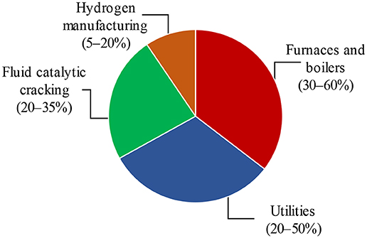
Figure 1. Overview of major CO2 emissions sources from refineries, adapted from Straelen et al. (2010) with permission from Elsevier.
Hydrogen manufacturing, which is responsible for 5–20% of CO2 emissions, produces concentrated CO2 streams at pressure giving relatively low CO2 capture costs. However, the combustion based CO2 emissions (process heaters and steam boilers) account for the major reason for the CO2 emissions from the typical refinery (Johansson et al., 2012; Bains et al., 2017). It is possible to reduce 9–40 MtCO2/year, which is equal to 6–26% of total refinery emissions, with short-term mitigation options such as energy efficiency measures and fuel shift (Straelen et al., 2010; Johansson et al., 2012). Additionally, there is a greater potential for the significant reduction of CO2 emission (5–80% of total refinery emissions) by the application of CCS technologies in the long term (Johansson et al., 2012). The regenerator in a FCC plant is typically responsible for roughly 20–35% of standard refinery CO2 emissions, which is the largest single source at the refinery (EPA, 2010; Straelen et al., 2010). However, a high-energy penalty and equipment requirements for the application of CCS technologies for FCC units are the main challenges CO2 capture.
Introduction to Fluid Catalytic Cracking (FCC)
In an oil refinery, FCC is one of the essential processes for the conversion of gas oils and heavier petroleum residues into more valuable gasoline, and distillate fuel products. The main aim of the process is to decrease the molecular weight of the feedstock to light cycle oil (LCO; C13-C20), gasoline (C5-C12), and LPG (C3-C4), but the production of light gases (H2, C1-C2) should be minimized. A commercial FCC unit, presented in Figure 2, consists of a catalytic reactor (a riser reactor) and a regenerator (Sadeghbeigi, 2000; Jones and Pujadó, 2006). Vogt and Weckhuysen (2015) presented the consecutive reactions of complex FCC feedstock leading to the final FCC products (Figure 2). The reactor is a riser in which the preheated feedstock is injected, vaporized, and mixed with hot catalyst and steam, with cracking temperatures of 480–600°C which decrease up to the riser as the endothermic cracking reactions proceed. The gas-phase cracked products and catalysts powders are separated in the disengagement zone, a cyclone. The gas-phase products are then sent to a fractional column while the coke deposited catalysts are stripped with steam to remove volatiles and then sent to the regenerator where the coke is combusted with air in a controlled manner at temperatures typically close to 750°C. After regeneration, coke free catalysts are sent back to the riser; thereby, the cycle is completed. Combustion of the coke generates heat to sustain the endothermic cracking reactions in the riser, so the system is thermally balanced. The concentration of CO2 in the flue gas is 0–5 vol.% with a low concentration of CO in the full combustion mode. Additionally, the flue gas contains 50–200 vppm of NOx and 300–600 vppm of SOx (Cheng et al., 1998).
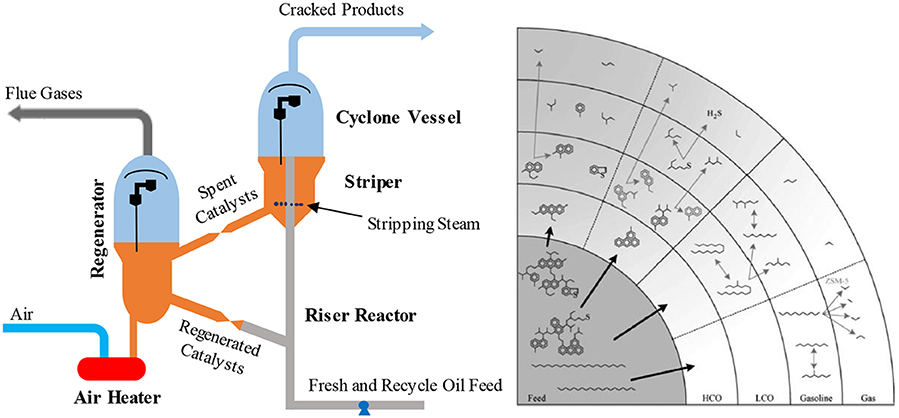
Figure 2. A typical FCC unit (left) adapted from Rawlence and Gosling (1988) with permission from Elsevier and the consecutive cracking involve in FCC feedstock (right), reprinted from Vogt and Weckhuysen (2015) with permission from the Royal Society of Chemistry (RSC) under the Creative Commons CC BY license.
Generally, type Y zeolite-based catalysts are the main catalyst used for the cracking reaction in FCC units. The zeolites can be modified with rare earth metals to increase acidity and improve thermal stability and dealuminated to provide even greater stability. Type Y zeolite catalysts also comprise an aluminosilicate matrix with mesoporosity and some acidity to crack larger molecules, clay to improve physical strength and a binder (Rawlence and Gosling, 1988). FCC units have been faced with increasingly stringent quality emission standards that require lower emissions of CO, NOx and SOx, and this together with the trend to heavier residue feedstock containing Ni and V has resulted in many innovations in catalyst formulations both maximize product selectivity and control these pollutants (Rawlence and Gosling, 1988). An FCC catalyst should have the critical properties shown in Figure 3.
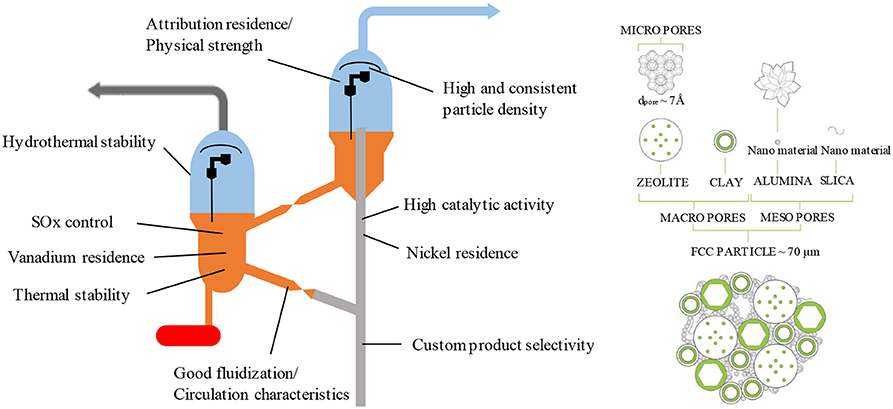
Figure 3. Catalyst properties required for an FCC unit (left), adapted from Rawlence and Gosling (1988) with permission from Elsevier and typical chemical and structural composition of an FCC particle (right) reprinted from Vogt and Weckhuysen (2015) with permission from the Royal Society of Chemistry (RSC) under the Creative Commons CC BY license.
As with the other industrial catalysts, selectivity, activity, attrition resistance and durability are the key performance attributes of FCC catalysts. Laboratory scale fixed-bed, fixed-fluid bed, or fluid transport of riser reactors have been ordinarily used to evaluate activity and product selectivity of an FCC catalyst (Otterstedt et al., 1988; Rawlence and Gosling, 1988; Gianetto et al., 1994; Al-Khattaf and De Lasa, 1999; Manos et al., 2001; Corma et al., 2007; Ng et al., 2007).
CO2 Capture Technologies for FCC
As described in the introduction, oil refineries are the third-highest CO2 emitter after power plants and cement industries (Gale et al., 2005; Straelen et al., 2010). N2O (0.08%) and CH4 (2.25%) are the other greenhouse gases which are emitted by refineries besides CO2 (97.67%) (EPA, 2010). The CO2 produced in the refineries come from several different units such as FCC, hydrogen production, sulfur recovery plants in addition to boilers and process heaters (combustion-related CO2 sources) (EPA, 2010; Straelen et al., 2010; Digne et al., 2014; Miracca, 2015). Although the FCC system is one of the most important units for a refinery, the regenerator part of FCC is responsible for roughly a quarter of standard refinery CO2 emissions at the refinery (EPA, 2010). For instance, a medium-size FCC unit, which has been fed 60,000 barrels per day (bpd), emits almost 0.5 million tons of CO2 per year to the atmosphere (Mello et al., 2015b). It is therefore clear that deploying CO2 capture to FCC would play a crucial role in fully decarbonizing oil refinery operations.
Based on the characteristics of the FCC process, post combustion capture (Elkamel et al., 2008; Peng and Zhuang, 2012; Digne et al., 2014; Miracca and Butler, 2015), oxyfuel combustion (Melien and Roijen, 2009; Mello et al., 2009a, 2013, 2015a,b; Miracca and Butler, 2015) and CLC (Güleç et al., 2019a,b, 2020) technologies have already been suggested to capture the CO2 released from the regenerator of FCC units. In FCC-post combustion capture, the CO2 in the flue gas can be captured using an amine scrubbing method. In FCC-oxyfuel combustion capture, oxygen mixed with recycled CO2 is used instead of air to oxidize the coke that deposited on the FCC catalyst during cracking reaction (Melien and Roijen, 2009; Mello et al., 2009a, 2013, 2015a; Miracca, 2015). In the FCC-CLC capture, the coke is combusted with oxygen carriers, which are supplied by an additional circulation through an air reactor integrated with the FCC regenerator (Güleç et al., 2019a,b, 2020). In addition to these technologies, Mace et al. (2009) suggested changing the regenerator in a FCC unit from a combustor to a steam gasifier to produce syngas (CO and H2) instead of H2O and CO2 with gasification of coke, in which the oxygen ratio may be reduced by increasing the ratio of CO2/O2 or H2O/O2 in the regenerator feed. However, Mace et al. (2009) also raised up some serious questions about regeneration of catalysts, the reverse Boudouard reaction without poisoning the catalysts, maintaining the heat balance on FCC unit, additional combustion source to provide all of the process heat, required partial pressure of H2O and CO2 etc. Although gasification of the coke deposited on FCC catalyst is an alternative way to CO2 capture, the uncertainty of the process conditions and lack of experimental study makes difficult to compare this process with other suggested technologies. On the other hand, because of the coke deposition on FCC catalyst, Pre-combustion cannot be applied to FCC (Miracca, 2015).
Post Combustion Capture
Post combustion is one of the CO2 capture technologies suggested for the FCC regenerator (Melien and Roijen, 2009; Mello et al., 2009a, 2013, 2015a,b; Crombie et al., 2011; Johansson et al., 2012; Digne et al., 2014; Miracca and Butler, 2015) where studies demonstrate that the technology can be retrofitted to the regenerator flue gas line containing 10–20% CO2 (Mello et al., 2015a,b). Straelen et al. (2010) report a case study on the deployment of post combustion CO2 capture at a complex large-scale refinery, consisting of a hydrogen production unit, a fluid catalytic cracker, and a group of smaller and larger utility plants, handling in the range of 400,000–500,000 bpd. The results demonstrate that application of post combustion to refineries is technically feasible. Miracca and Butler (2015) described a system for an FCC unit with CO2 capture modifications established downstream from the FCC unit, as presented in Figure 4 (Miracca and Butler, 2015). In this system, the flue gas, which is released from the regenerator, is fed to an amine scrubbing system by a flue gas blower. The CO2 is chemically absorbed by an aqueous amine solution and then very high purity (99.5% vol.) CO2 is desorbed in the stripper unit. The results of the study illustrate that 85% of CO2 can be captured from flue gas using a commercial post combustion capture technology with a suitable amine solvent (Miracca and Butler, 2015).
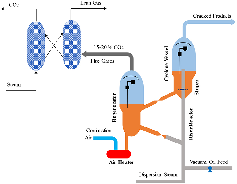
Figure 4. Post-combustion capture for a FCC, adapted from Miracca and Butler (2015) with permission from BP Group Technology.
Digne et al. (2014), undertook a techno-economic evaluation of a commercial post combustion CO2 capture technology, named HiCapt+ (Figure 5) developed by IFP Energies Nouvelles and PROSERNAT, for FCC flue gas. To evaluate HiCapt+, a case study for a capacity of 60,000 bpd was considered. As for any amines scrubbing operation, HiCapt+ process consists of three main units; the absorber, stripper, and CO2 compressors. The process was described as follows; flue gas, which is cooled down to 50°C by a water quench tower, is introduced at the bottom of the absorber at atmospheric pressure. The lean solvent is an aqueous solution containing 40 wt.% of monoethanolamine (MEA) also enters at the top of the absorber. The CO2 in flue gas diffuses to the solvent and react with MEA. The gas described as a decarbonized is then sent to the washing section zone of the absorber. In this section, MEA in the vapor is recovered by water washing. Decarbonized flue gas is, then, released to the atmosphere from the top of the absorber. After a heat recovery exchanger, the solvent highly loaded CO2 is introduced to the regenerator (also called the stripper) at a pressure ~1–2 bar. The heated solvent is pumped through the packed stripper column. The solvent recovered from the stripper column is sent to the absorber from the bottom of the regenerator, and after a condensation unit, the high purity (99.9 mol%) CO2 separated from the solvent is delivered to the CO2 compression unit. Here, the CO2 compressed at 110 barg in several stages of compression and condensation (Digne et al., 2014). From a technical point of view, because of the HiCapt+ inlet specifications, 74% of CO2 emitted from the FCC unit can be captured, ~14% of total CO2 emitted from the refinery under consideration.

Figure 5. Simplified process flow diagram of the HiCapt+ process, reprinted from Digne et al. (2014) with permission from IFP Energies nouvelles (Oil & Gas Science and Technology).
Wei et al. (2018) have also demonstrated the integration of solvent-based carbon capture with FCC through process simulation. An industrial scale FCC unit (1.4 million tons VGO per year) was modeled in which different heat integration options were considered to reduce the energy penalty. Further, the model was validated through industrial operating data. As demonstrated in Figure 6, three different cases were suggested to provide the energy required for the carbon capture plant after the regenerator. In case-1, the heat required by the CO2 capture plant was completely supplied by the excess heat of the FCC unit coming from the waste heat steam generator (WHSG) and the heat exchanger located after the chimney, which was calculated as 11.52 MWth. In case 2, 90% CO2 capture from the regenerator was ensured using the only excess heat of the FCC unit, which was calculated as 14.67 MWth. The additional 3.15 MWth in case-2 came from the energy produced in the flue gas turbine. In case 3, 90% CO2 capture was also secured using an additional heat supply. The results indicated that a proper design of heat integration would significantly decrease the energy penalties for CO2 capture in FCC units.
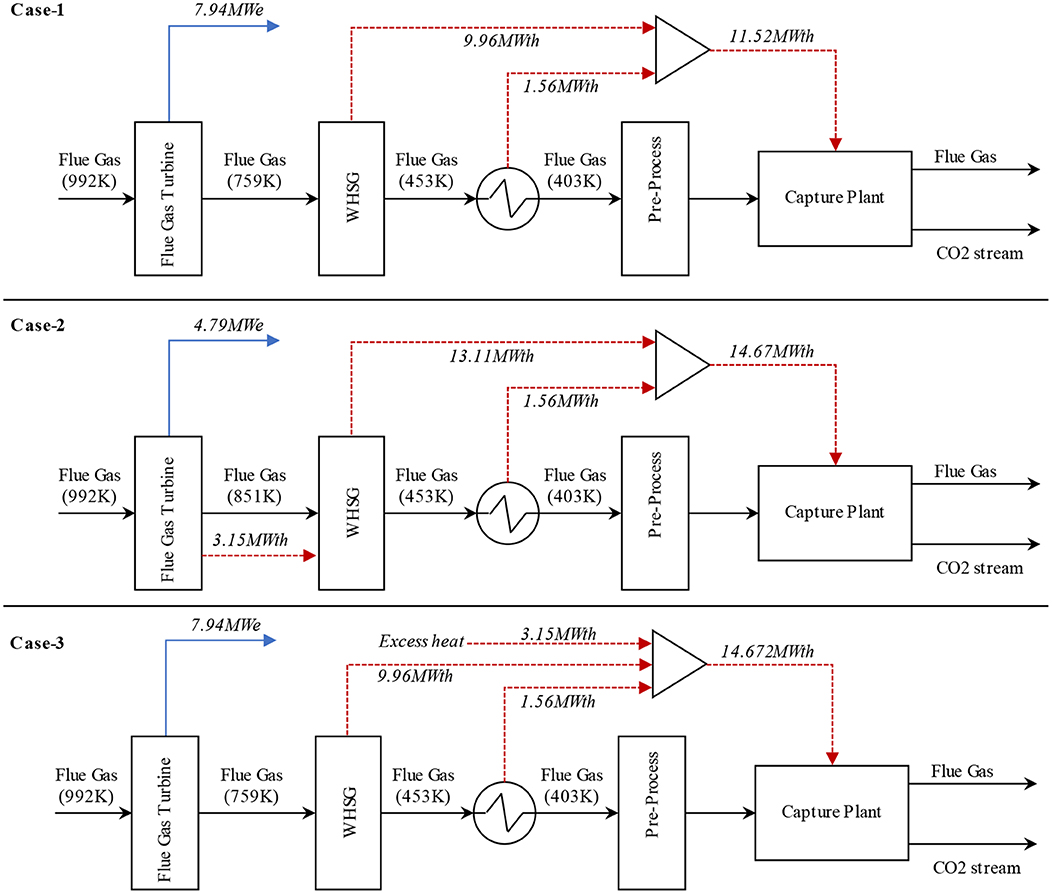
Figure 6. Process flow diagram presenting three different heat integration options with post-combustion capture for the flue gas released from the regenerator of the FCC unit, adapted from Wei et al. (2018) with permission from Elsevier.
Oxyfuel Combustion
Oxyfuel combustion is another technology proposed to capture CO2 from the FCC regenerator (Santos et al., 2008; Melien and Roijen, 2009; Mello et al., 2009a, 2013, 2015a,b; Miracca, 2015; Silva et al., 2015). High purity oxygen is used in the regenerator to produce a flue gas consisting of mainly CO2 and H2O. The application of oxyfuel combustion to the regenerator is illustrated in Figure 7 (Mello et al., 2009a; Miracca and Butler, 2015). An air separation unit (ASU) produces the pure oxygen for use in the regenerator, which is then mixed with CO2 recycled from the dehydration unit. This mixture is then sent to the regenerator for the combustion of coke deposited on FCC catalyst. Thanks to the pure oxygen used in the combustion, the flue gas released from the regenerator consist of 85–93% of CO2 by volume (Mello et al., 2013, 2015b; Miracca and Butler, 2015) balanced moisture which can be separated by dehydration unit. Due to the flue gas compression, partial bypass to the stack is not required, which gives oxyfuel combustion an inherent boost on CO2 recovery compared to post combustion capture (Miracca and Butler, 2015).
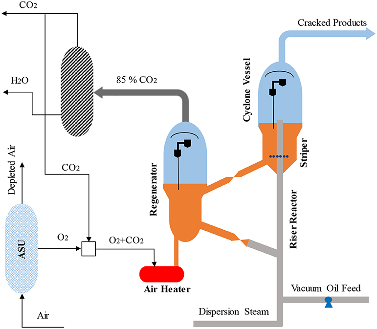
Figure 7. Oxy-combustion capture in FCC units adapted from Miracca and Butler (2015) with permission from BP Group Technology.
Mello et al. (2013, 2015b) also demonstrated the technical viability of oxyfuel combustion for a pilot-scale retrofitted FCC unit operated by Petrobras (Brazil). An oxygen supply system and a CO2 recycling system was retrofitted to a pilot-scale FCC unit, as demonstrated by Mello et al. (2013). The major equipment for the oxygen supply system is a liquid O2 tank, vaporiser system, flow and pressure control skid, gaseous O2 injector, and piping. To define the technical feasibility of oxyfuel combustion, heat balance and volumetric flow rate tests were carried out with two different FCC feeds; an Atmospheric Residue (ATR) and a typical vacuum gas oil (VGO) (Mello et al., 2013). Furthermore, catalyst balance and catalyst deactivation tests were performed using VGO. Due to the different properties of CO2 and N2, including density and heat capacity, it is important to evaluate the same heat balance and volumetric flow rate conditions (Mello et al., 2013). The results demonstrated that an oxyfuel combustion FCC unit might be run in the same heat balance conditions as air operation once the CO2 flow rate in the regenerator is kept lower than the N2 flowrate with air combustion. Moreover, there is no impact on the thermal balance of the unit, and very few changes occurred in the product yields. The retrofitted system may also be run with the same inert volumetric flow rate, but the thermal balance of the unit and product distributions are affected because of the heat capacity of CO2, compared with the nitrogen, as demonstrated in Figure 8. The effects of using the same heat balance as for air are the temperature decrease, higher catalyst circulation and feed conversion. For the same volumetric flowrate are an increase in the distribution of gasoline and LPG because of the decreasing bottom products (Mello et al., 2015b). The catalysts did not show a significant deactivation by increasing the partial pressure of oxygen in the regenerator (Mello et al., 2013, 2015b).
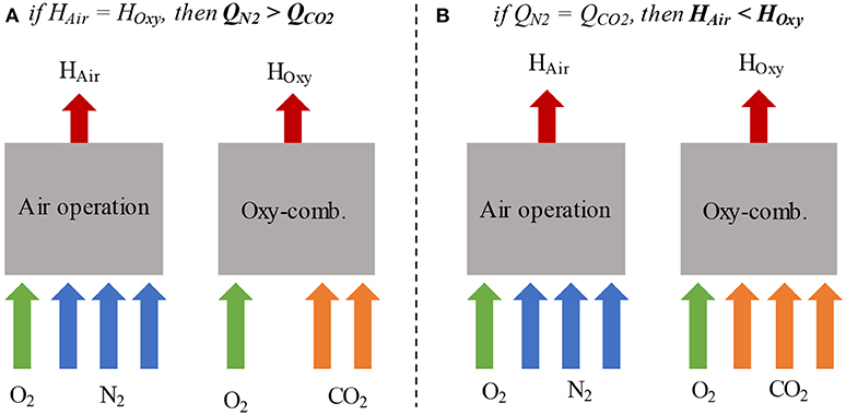
Figure 8. Oxy-combustion and air operation in the (A) same heat balance and (B) same volumetric flow rate, adapted from Mello et al. (2013) with permission from Elsevier.
Miracca and Butler (2015) have also summarized technical and economic evaluation of oxyfuel combustion using two different oxygen purity cases; case 1 with 97% oxygen purity and case 2 with 99.5%. The overall capture rate was 90% of CO2 for case 1 and 99.98% for case 2 (Miracca and Butler, 2015). In both instances, the ASU is responsible for the highest power consumption, 11.4 and 15.9 MW, respectively. Because of the higher oxygen purity in case 2, power consumptions for flue gas recycle compression (7.5 MW), and CO2 purification and compression (6.4 MW) are lower than those of Case-1 (9.8 and 9.1 MW, respectively). Although ASU consumes more power in case 2, the total power consumption (32.5 MW) is slightly lower than in case 1 (34.2 MW, Miracca and Butler, 2015).
In addition to the feasibility studies of oxyfuel combustion for FCC, Santos et al. (2008) and Silva et al. (2015), focused on the reactions occurred in the regenerator. Santos et al. (2008) reported mechanistic insights of coke-CO2 reactions in the regenerator. Coke functionality, especially aliphatic carbon, having much more influence on the CO2-coke reaction than O2-coke reaction. Furthermore, Silva et al. (2015) have explained the reverse Boudouard reaction over vanadium, lithium, magnesium, potassium, calcium and sodium modified alumina, which occurs for the coke deposited FCC catalyst. Potassium and vanadium modified alumina showed a synergism for the CO2 coke reaction, which released 13CO followed by 12CO and 12CO2. In reverse Boudouard reaction, 12CO and 12CO2 are affected by catalyst types and reaction temperatures. During regeneration, besides CO2 capture, the FCC process may have an important role to supply CO for other processes (Santos et al., 2008; Silva et al., 2015). A two-stage regenerator system was suggested, as presented in Figure 9 (Silva et al., 2015). In the first step, the Reverse Boudouard reaction would be favored using high CO2 and low O2. In the second stage, residual coke would be combusted by highly pure O2. The second stage would also provide energy to the first stage and the overall FCC process (Silva et al., 2015).
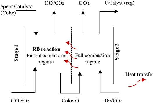
Figure 9. Two-stage FCC regeneration with diathermy wall provides heat transfer between the stages, reproduced from Silva et al. (2015) with permission from Elsevier.
Chemical Looping Combustion (CLC)
The other possible CO2 capture technology for FCC is CLC (Güleç et al., 2019b, 2020), which can naturally separate the oxygen from the air by reaction with the reduced oxygen carrier and so does not require a CO2 separation process.
The CLC process is based on oxygen transfer from an air reactor to fuel reactor using a solid oxygen carrier. The main advantage of the CLC process compared to conventional combustion is that CO2 is not diluted with N2 in the combustion gases, and so highly concentrated CO2 is obtained without any extra energy needed (Abad et al., 2007). Firstly, the fuel (such as coal, petroleum coke, biomass, and solid wastes) is introduced to the fuel reactor and oxidized to CO2 and H2O by an oxygen carrier, MenOm (such as CuO, NiO, Mn2O3, Co3O4 etc.) (Adanez et al., 2012), which is reduced to metal (Men) or any other reduced state (MenOm−1) during this reaction. After a condensation and purification step the flue gas, pure CO2, is ready for transport and storage (Wang et al., 2015). In a second reactor, the reduced oxygen carrier (MenOm−1) is oxidized by oxygen in an air stream. The re-oxidized oxygen carrier (MenOm) is then ready for the next combustion cycle. The flue gas from the air reactor just contains nitrogen and any excess oxygen (Chiu and Ku, 2012; Wang et al., 2015). Although the preliminary investigations about solid fuel CLC have mainly focused on power generation, Güleç et al. (2019a,b) experimentally demonstrated that it is possible to combust the coke deposited on an FCC catalyst with oxygen carriers, such as CuO, Co3O4, and Mn2O3. The concept is supported by earlier solid fuel CLC studies (Cao et al., 2006; Scott et al., 2006; Mattisson et al., 2009; Dennis and Scott, 2010; Dennis et al., 2010; Adanez et al., 2012; Ksepko et al., 2012).
The combustion mechanisms (Syngas-CLC, iG-CLC, and CLOU) for solid fuels are presented in Figure 10. Because of the difficulties in solid-solid reactions, the solid fuel-CLC process is facilitated by fluidisation with CO2 and H2O, the gasifying agents (Mattisson et al., 2009). Lyngfelt (2014) described how the overall extent of solid fuel combustion reflects how well the gases released from the solid fuel, i.e., volatiles and syngas, have been oxidized to CO2 and H2O by the oxygen carriers. Using a suitable CLC unit, a gas conversion of around 75–95% is possible depending on the fuel, oxygen carrier and solids inventory (Lyngfelt, 2014). Moreover, fuels with little or no volatile material, such as FCC coke, show higher gas conversions (Lyngfelt, 2014).
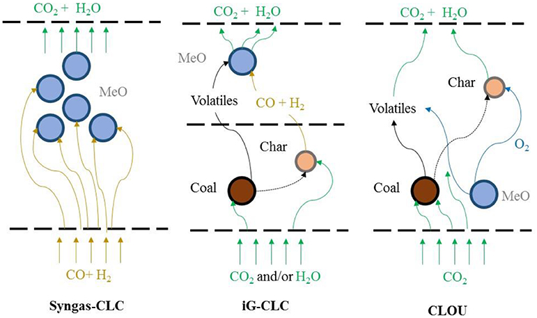
Figure 10. Combustion mechanisms of solid fuels with oxygen carriers, adapted from Adanez et al. (2012) with permission from Elsevier.
Güleç et al. (2019a) have proposed a novel CLC-FCC concept, as illustrated in Figure 11, with two loops (i) regenerator—FCC riser reactor and (ii) air reactor—regenerator. The regenerator works as both the catalyst regenerator in the first loop and the fuel reactor where the coke is combusted with oxygen carriers in the second loop (CLC). FCC catalysts need to be modified with an oxygen carrier for this new concept (Güleç et al., 2019a, 2020). The oxygen carrier in the fresh catalyst will be in a reduced state (MenOm−1/Cat) as it enters the FCC riser reactor. The spent or deactivated catalyst with deposited coke going to the regenerator is assigned as Coke/MenOm−1/Cat. Similarly, the reduced oxygen carrier modified FCC catalyst (MenOm−1/Cat) is also circulated to the air reactor, another fluidised bed, where the reduced oxygen carrier is oxidized and designated as MenOm/Cat. By mixing of Coke/MenOm−1/Cat and MenOm/Cat catalysts in the regenerator, the deposited coke would be oxidized to CO2 thanks to the oxygen supplied through oxygen carrier modified on FCC catalyst. The coked catalysts are hence regenerated. The MenOm−1/Cat circulates back to the FCC riser reactor and the air reactor. Given that the cracking and metal oxidation reactions are fast in relation to the oxidized metal coke combustion, the average coke content of the catalyst in the regenerator would be low meaning that little CO2 would be lost through combustion in the air reactor where the residence time would be short. The equations for CLC of carbon below indicate that all heat is generated in the air reactor and this needs to balance the heat required for the combustion and cracking reactions.
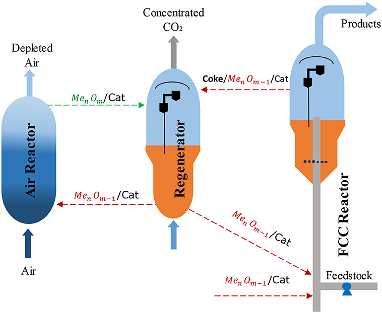
Figure 11. Schematic diagram of the proposed CLC-FCC process, reprinted from Güleç et al. (2019a, 2020) with the permission from Elsevier.
Regenerator : 4CuO(s)+C(s) → 2Cu2O(s)+CO2(g) Δ −110.68 kJ/mol (2.1*)
Air reactor : 2Cu2O(s)+O2(g) → 4CuO(s) Δ −282.82 kJ/mol (2.2*)
Net reaction : C(s)+O2(g)→CO2(g) Δ −393.51 kJ/mol (2.3)
*Δ and Δ are the standard heats of reaction for the reduction ad oxidation at 298K and 1 atm.
NOx emissions from the regenerator of FCC demand a control strategy (Cheng et al., 1998; Sadeghbeigi, 2000) and CLC would be advantageous in that NOx emissions are lower than for normal combustion (Cao et al., 2006; Adanez et al., 2012). Also, the gas leaving from the air reactor can also be expected to be essentially free of NOx (Lyngfelt, 2014).
Güleç et al. (2019a) observed no significant effects of reduced oxygen carriers such as Cu, Cu2O, CoO, and Mn3O4, on the cracking reaction in terms of conversion, yield, and product selectivity. However, in another study, Güleç et al. (2019b) demonstrated that higher hydrocarbons such as n-hexadecane and n-heptane could be combusted with oxidized oxygen carriers such as CuO and Mn2O3, at low temperatures, 500°C, which is the cracking temperature in the FCC riser. To keep product selectivity and conversion the same, circulating reduced oxygen carriers modified FCC catalyst between regenerator and riser reactor is very important. Furthermore, the CLC tests of coke with oxygen carriers; CuO, Co3O4, and Mn2O3, demonstrated that complete combustion is possible once the stoichiometrically required amounts of oxygen carriers are used with sufficiently long residence times (Güleç et al., 2019a, 2020). Over 90 wt% coke combustion coke was achieved with CuO and Mn2O3 at 750°C for 40–60 min (Güleç et al., 2019a, 2020), similar conditions to those used in the conventional FCC regenerators (Arbel et al., 1995; Corma et al., 2007).
Technical Evaluation of CO2 Capture Technologies
Although post combustion capture, oxyfuel combustion and CLC are applicable for CO2 capture, technical and economic evaluation have an important role in establishing pilot or commercial scale FCC units with low CO2 emissions. While there is no need for any modification to the FCC regenerator under for post combustion capture, the regenerator and its operating conditions must be modified for the application of oxyfuel combustion and CLC. A summary of the flue gas composition and CO2 capture levels are presented in Table 1 for the three technologies.
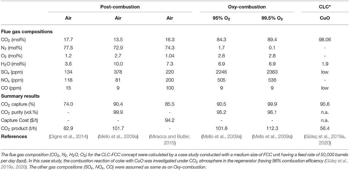
Table 1. Flue gas compositions and summary results.
The flue gas composition for post combustion capture is the same as for a commercial FCC unit. From a technical point of view, because of the HiCapt+ inlet specifications presented by Digne et al. (2014), FCC flue gas was able to be treated with 74% CO2 capture for conventional FCC regenerator. Miracca and Butler (2015) and Mello et al. (2009a) demonstrated 85 and 90% CO2 capture levels.
Bench-scale tests for oxyfuel combustion demonstrated the regeneration of coke with O2 mixed CO2 (Hicks et al., 2008; Santos et al., 2008; Melien and Roijen, 2009; Mello et al., 2009a; Miracca and Butler, 2015). Moreover, larger-scale tests showed that oxyfuel combustion is also technically feasible for the FCC regenerator (Santos et al., 2008; Mello et al., 2009a). Compared to post combustion capture, oxyfuel combustion offers much higher CO2 capture levels depending on the oxygen purity used in the regenerator; when oxygen purity increases from 95 to 99.5%, the CO2 capture increases from about 90.52 to 99.99%. Additionally, there are no significant changes in the stability of operation, the product profile, and effectiveness of coke burn (Mello et al., 2009a). The operation of FCC unit with oxyfuel combustion is considered to be more flexible than post combustion capture, and also it requires less area (Miracca and Butler, 2015).
In addition to these two technologies, CLC-FCC offers promise to produce concentrated CO2, with a capture levels higher than 96% thanks to the oxygen separation by oxygen carriers from air reactor to regenerator (Güleç et al., 2019a, 2020). The challenges of the CLC-FCC concept are (i) reformulating FCC catalysts to include sufficient oxygen carrier capacity; (ii) selecting oxygen carriers that would not negatively affect the cracking activity of the catalyst and the coke yield, (iii) modifying the FCC process to include the air reactor (Güleç et al., 2019b, 2020). For example, iron-containing clays were the first catalysts used for cracking reactions, and, if it is used as an oxygen carrier, would impact on cracking and coke formation (Rawlence and Gosling, 1988). Additionally, the modification of FCC catalyst with oxygen carriers should not significantly increase the overall mass of the catalyst to maintain similar catalyst to oil ratios and the heat balances currently used in FCC. As for the selecting of oxygen carriers, many other transition metals than Fe are available including Cu-, Mn- and Co- that have no significant effects on the cracking reaction (Güleç et al., 2019a,b, 2020) under a suitable configuration where the air reactor is integrated with FCC unit as demonstrated in Figure 11.
Economic Evaluation of Suggested CO2 Capture Technologies
A preliminary evaluation can be attempted for the different CO2 capture technologies for FCC, although the cost uncertainties for CLC-FCC at this stage are high. Due to the high ASU cost, the total installed cost for oxyfuel combustion unit is calculated to be ~2 times higher than for a post combustion capture unit (Mello et al., 2009a). Similarly, the total capital investment for oxyfuel combustion is estimated at ~1.5 times higher than Post combustion based on medium size of FCC unit (60,000-62,000 bpd) by Miracca and Butler (2015) and Melien and Roijen (2009). Table 2 presents the capital costs with an accuracy of ±30% and associated with post combustion capture and oxyfuel combustion (O2 purity: 99.5 and 95.0%) presented by Mello et al. (2009b). Additionally, the relative contributions of CO2 capture technologies to the total capital cost is presented in Figure 12. In this calculation, the capital cost of oxyfuel combustion method is about 193.3 M$ which is nearly 45% higher than for post combustion capture. Melien and Roijen (2009) also determined the capital cost as 126 M€ for post combustion capture and 178 M€ for oxyfuel combustion.
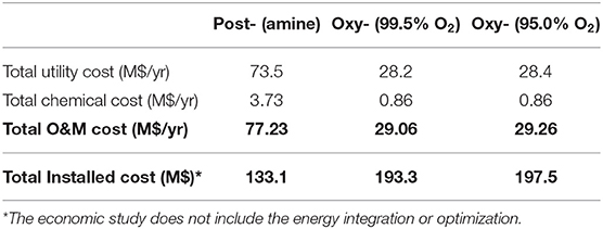
Table 2. Total installed Operation and Maintenance (O&M) costs (Mello et al., 2009b).
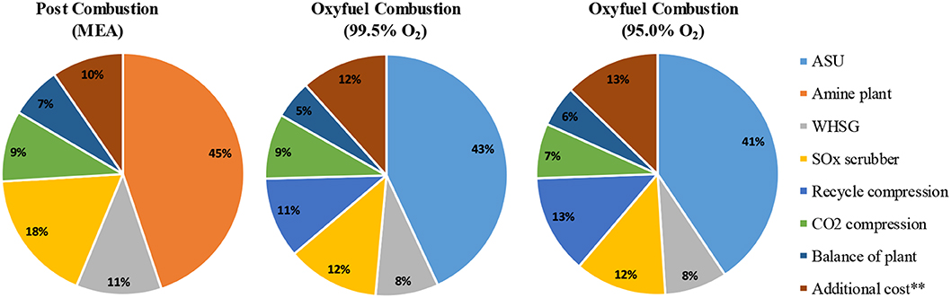
Figure 12. Relative contribution of CO2 capture technologies to total capital cost (**additional costs includes dehydration, home office engineering, insurance and profit), adapted from Mello et al. (2009a) with permission from Elsevier.
Although it is possible to decrease the total capital cost for oxyfuel combustion by decreasing the oxygen purity used in the regenerator, the requirement of the propane refrigeration system and larger recycling compressors resulted in an overall higher investment as noted by Mello et al. (2009b). On the other hand, Lemaire et al. (2011) and Digne et al. (2014) have indicated that the HiCapt+ process using 40% MEA solution gives a 15% reduction in the cost of an amine scrubbing plant compared to using only 30% MEA. Although post combustion capture for FCC regenerator has a lower capital cost (Crombie et al., 2011), oxyfuel combustion indicated a lower CO2 capture and avoided cost than post combustion (Melien and Roijen, 2009; Mello et al., 2009a). In another study, the Inside Battery Limit cost, which is the cost of purchasing and installing all process equipment, for an FCC unit with CO2 capture is determined to be 1.25 times higher than that of an FCC unit without capture (Digne et al., 2014). Although no cost analysis of the CLC-FCC concept is attempted, the air reactor used for the oxidation of reduced oxygen carriers would be an additional installed cost. The other utilities such as waste heat steam generator, SOx scrubber, dehydration unit, and CO2 compressors should almost be the same as for oxyfuel combustion technology as the flue gas released from the CLC-FCC concept is similar to that released in oxyfuel combustion. The air blower, which is used in a conventional FCC unit, can also be used as the air blower required for the air reactor.
Most of the energy consumption in post combustion capture is due to solvent regeneration in the boiler (Abu-Zahra et al., 2007). Additionally, besides the capture solvent and technology, the concentration of CO2 in flue gas also influences the capture cost (Straelen et al., 2009). The energy penalty (specific duty) for the application of post combustion capture to an industrial scale FCC unit was reported as 4.2 GJ/t CO2 (for CO2 capture level of 90%) and this decreased to 3.8 GJ/t CO2 with the modification of heat integration option case 1 having a CO2 capture level of 78% (Figure 6, Wei et al., 2018). Furthermore, the novel post combustion capture technology, HiCapt+, specifically developed for FCC units by Digne et al. (2014) gavean energy consumption of 3.1–3.3 GJ/t CO2, for 74% CO2 capture. The CO2 avoided cost was determined as 75–110 €/t CO2 for the application of post combustion to a medium sized FCC unit (Melien and Roijen, 2009; Miracca and Butler, 2015). It was also determined between 90 and 120 €/t CO2 if the current amine capture technology is modified to the refineries (Straelen et al., 2009).
The application of oxyfuel combustion to FCC was demonstrated to have a lower energy penalty than post-combustion capture of 1.8–2.5 GJ/t CO2 depending on oxygen purities of 95 to 99.5%. The energy penalty for oxyfuel combustion arises from the ASU, oxygen and flue gas recycle compression. Further, oxyfuel combustion provides lower CO2 avoided costs of 55–85 €/t CO2 compared to post-combustion capture (Melien and Roijen, 2009; Mello et al., 2009a; Miracca and Butler, 2015). Although the energy penalty was calculated to be as low as 0.5 GJ/t CO2 for the application of post combustion capture due to the lower net power consumption than oxyfuel combustion (Melien and Roijen, 2009; Mello et al., 2009b; Miracca and Butler, 2015), there is no clear explanation as why this is the case. As for the application of CLC to FCC unit, the significant additional costs of CLC unit is associated with the CO2 compression (Lyngfelt, 2014). In order to evaluate the performance of proposed CLC-FCC unit (Güleç et al., 2019a,b, 2020), a case study was conducted with a medium size of FCC unit having a vacuum gas oil (VGO) feed rate of 50,000 bpd. The case study composed a heat and mass balance around the proposed CLC-FCC unit with the experimental data presented in Güleç et al. (2019a). Thanks to this case study, the energy penalty was determined as 0.2 GJ/t CO2. In terms of capture cost, a comparison of the first design of CLC solid fuel power plant in an EU project to the similar fluidized bed indicated a low-efficiency penalty as well as a low capture cost, 10–40 €/t CO2 (Ekström et al., 2009). However, it is still unknown as to what extent capital costs of the FCC unit will be higher than for the case considered here.
The total O&M costs for post combustion capture was much higher than that for oxyfuel combustion as presented in Table 2. The high utility cost for post combustion capture was attributed to the demanding low-pressure (LP) steam required for the amine regeneration and extra cooling tower water needed (Mello et al., 2009b). Additionally, the higher chemical cost for post combustion capture was also attributed to the requirements of MEA, corrosion inhibitor, particulate filters, activated carbon to remove hydrocarbons, sodium carbonate to reclaim MEA plus disposal costs. Such chemical costs are not required for oxyfuel combustion applications.
For CLC-FCC, cracking catalysts need to be modified with oxygen carriers such as CuO, Co3O4, Mn2O3, for the CLC cycle between the regenerator and oxidiser. Thanks to the low proportion of coke on equilibrium catalysts during typical FCC operation, a relatively low amounts of oxygen carriers would be required for regeneration (Güleç et al., 2019a, 2020). Although the relatively small amount of fresh oxygen carrier would not expect to increase the capture cost in a CLC process, the oxygen carrier cost needs to be considered carefully because of the natural decay of activity during many reduction-oxidation cycles. Based on the oxygen transfer capacity, an energy balance and a thermodynamics analysis, CuO seems to be the best choice as an oxygen carrier for the CLC system of solid fuels (Cao et al., 2006). So, in all, the additional costs for such a CLC system would be expected not to be excessive in comparison to other CO2 capture technologies (Lyngfelt, 2014). Although this work may not accurately reflect the additional capital cost for the construction of a CLC_FCC unit, it provides a useful indicator for establishing the economic viability of this process and comparing to the competing capture processes.
In summary, even though post combustion CO2 capture for FCC looks like a mature technology, the overall cost per ton of CO2 capture appears to be significantly higher than for oxyfuel combustion. Therefore, breakthrough technological developments, such as improve solvents are required to make post-combustion couture more competitive (Straelen et al., 2009). Although the studies to date demonstrate that oxyfuel combustion looks to be a promising technology for CO2 capture from the FCC regenerator, it still requires further improvements before commercial applications (Mello et al., 2013, 2015b; Miracca and Butler, 2015). As a high-energy penalty and requirements for extra equipment are apparent with both these technologies. CLC may well be a technology that provides a unique potential for avoiding the significant costs and energy penalties inherent in gas separation and CO2 capture. Nevertheless, more research and development are still required, especially with respect to finding the best design of the fuel reactor system and the combustion reaction mechanisms between coke and oxygen carriers in the regenerator (Ekström et al., 2009; Lyngfelt, 2014; Güleç et al., 2019a,b, 2020).
Additionally, a cost reduction in the application of post combustion, oxyfuel combustion and CLC to FCC unit would be possible with the developments of CCS technologies. Although amine absorption is currently at a high technology readiness level (TRL), an advanced absorption process, in which amine solvents and flue gases in a cross-flow system, can reduce both O&M and installed costs. Additionally, developing advanced, environmentally friendly, and cheap sorbents such as metal-organic frameworks, zeolites, activated carbons and amine-modified silica would potentially decrease the costs for the post combustion application (Samanta et al., 2012). Although CLC is currently at relatively low TRLs, developing advanced oxygen carriers at a low cost and upscaling of metal oxides should be further pursued to decrease the potential application cost of CLC technology (Wang et al., 2014). Furthermore, the development of membrane technology may enable to develop advanced ASU, which might be an option to significantly decrease the costs of oxyfuel combustion compared to the traditional cryogenic distillation (Mat and Lipscomb, 2019).
Conclusions
Post combustion technology can be retrofitted after the regenerator flue gas line using a suitable amine scrubbing technology. Therefore, this technology does not require any operating modifications to the conventional FCC unit for the capture of typically 90% CO2. However, the total cost of the required chemicals for this system increases the cost significantly. As for oxyfuel combustion, the operating conditions of the FCC regenerator must take account of the different heat capacity and specific gravity of CO2. Furthermore, the total installed cost of the system was high due to the ASU cost. However, it is possible to capture more than 95% CO2 released from the regenerator using high oxygen purity. Additionally, there is no or little chemical and utility cost unlike for post combustion capture. On the other hand, more extensive studies may be required at pilot plant before scale up to a commercial demonstration. CLC is another promising technology for CO2 capture from the FCC regenerator. There is no need for any separation process unlike for post combustion capture oxyfuel combustion technologies, which significantly reduces the CO2 capture cost. However, capital costs are higher due to the resin of FCC units to accommodate the oxidiser. Moreover, NOx emissions are an important issue in FCC demanding a control strategy and this technology should give low NOx emissions than normal or oxyfuel combustion. However, the operating conditions might be changed because of the new generation FCC catalysts required. Therefore, further lab scale and pilot scale activities are required to be clarified the operating conditions of this concept.
Author Contributions
FG completed the literature and wrote the manuscript with CS and WM who decided the overall scope and content.
Funding
This work was supported by the Engineering and Physical Sciences Research Council (grant number EP/P026214/1), as part of the UK CCS Research Center.
Conflict of Interest
The authors declare that the research was conducted in the absence of any commercial or financial relationships that could be construed as a potential conflict of interest.
References
Abad, A., Adánez, J., García-Labiano, F., Luis, F., Gayán, P., and Celaya, J. (2007). Mapping of the range of operational conditions for Cu-, Fe-, and Ni-based oxygen carriers in chemical-looping combustion. Chem. Eng. Sci. 62, 533–549. doi: 10.1016/j.ces.2006.09.019
Abu-Zahra, M. R., Schneiders, L. H., Niederer, J. P., Feron, P. H., and Versteeg, G. F. (2007). CO2 capture from power plants: part I. a parametric study of the technical performance based on monoethanolamine. Int. J. Greenhouse Gas Control. 1, 37–46. doi: 10.1016/S1750-5836(07)00032-1
Adanez, J., Abad, A., Garcia-Labiano, F., Gayan, P., and Luis, F. (2012). Progress in chemical-looping combustion and reforming technologies. Prog. Energy Combust. Sci. 38, 215–282. doi: 10.1016/j.pecs.2011.09.001
Ali, M., Saidur, R., and Hossain, M. (2011). A review on emission analysis in cement industries. Renew. Sust. Energy Rev. 15, 2252–2261. doi: 10.1016/j.rser.2011.02.014
Al-Khattaf, S., and De Lasa, H. (1999). Activity and selectivity of fluidized catalytic cracking catalysts in a riser simulator: the role of Y-zeolite crystal size. Ind. Eng. Chem. Res. 38, 1350–1356. doi: 10.1021/ie980433z
Arbel, A., Huang, Z., Rinard, I. H., Shinnar, R., and Sapre, A. V. (1995). Dynamic and control of fluidized catalytic crackers. 1. modeling of the current generation of FCC's. Ind. Eng. Chem. Res. 34, 1228–1243. doi: 10.1021/ie00043a027
Bains, P., Psarras, P., and Wilcox, J. (2017). CO2 capture from the industry sector. Prog. Energy Combust. Sci. 63, 146–172. doi: 10.1016/j.pecs.2017.07.001
Cao, Y., Casenas, B., and Pan, W.-P. (2006). Investigation of chemical looping combustion by solid fuels. 2. redox reaction kinetics and product characterization with coal, biomass, and solid waste as solid fuels and CuO as an oxygen carrier. Energy Fuels 20, 1845–1854. doi: 10.1021/ef050424k
Cheng, W. C., Kim, G., Peters, A., Zhao, X., Rajagopalan, K., Ziebarth, M., and Pereira, C. (1998). Environmental fluid catalytic cracking technology. Catal. Rev. 40, 39–79. doi: 10.1080/01614949808007105
Chiu, P. C., and Ku, Y. (2012). Chemical looping process-a novel technology for inherent CO2 capture. Aerosol. Air Qual. Res. 12, 1421–1432. doi: 10.4209/aaqr.2012.08.0215
Clarens, F., Esp,í, J. J., Giraldi, M. R., Rovira, M., and Vega, L. F. (2016). Life cycle assessment of CaO looping versus amine-based absorption for capturing CO2 in a subcritical coal power plant. Int. J. Greenh. Gas Con. 46, 18–27. doi: 10.1016/j.ijggc.2015.12.031
Corma, A., Sauvanaud, L., and Occellli, M. (2007). Fluid Catalytic Cracking VII: Materials, Methods and Process Innovations. Amsterdam: Elsevier.
Crombie, M., Imbus, S., and Miracca, I. (2011). CO2 capture project phase 3 — demonstration phase. Energy Proc. 4, 6104–6108. doi: 10.1016/j.egypro.2011.02.617
Dennis, J. S., Müller, C. R., and Scott, S. A. (2010). In situ gasification and CO2 separation using chemical looping with a Cu-based oxygen carrier: performance with bituminous coals. Fuel 89, 2353–2364. doi: 10.1016/j.fuel.2010.01.037
Dennis, J. S., and Scott, S. A. (2010). In situ gasification of a lignite coal and CO2 separation using chemical looping with a Cu-based oxygen carrier. Fuel 89, 1623–1640. doi: 10.1016/j.fuel.2009.08.019
Digne, R., Feugnet, F., and Gomez, A. (2014). A Technical and economical evaluation of CO2 capture from Fluidized Catalytic Cracking (FCC) flue gas. Oil Gas Sci. Technol. 69, 1081–1089. doi: 10.2516/ogst/2013209
Ekström, C., Schwendig, F., Biede, O., Franco, F., Haupt, G., De Koeijer, G., et al. (2009). Techno-economic evaluations and benchmarking of pre-combustion CO2 capture and oxy-fuel processes developed in the European ENCAP project. Energy Proc. 1, 4233–4240. doi: 10.1016/j.egypro.2009.02.234
Elkamel, A., Ba-Shammakh, M., Douglas, P., and Croiset, E. (2008). An optimization approach for integrating planning and CO2 emission reduction in the petroleum refining industry. Ind. Eng. Chem. Res. 47, 760–776. doi: 10.1021/ie070426n
EPA (2010). Available and Emerging Technologies for Reducing Greenhouse Gas Emissions From Petroleum Refining Industry. Environmental Protection Agency.
Figueroa, J. D., Fout, T., Plasynski, S., Mcilvried, H., and Srivastava, R. D. (2008). Advances in CO2 capture technology, the US department of energy's carbon sequestration program. Int. J. Greenh. Gas Con. 2, 9–20. doi: 10.1016/S1750-5836(07)00094-1
Gale, J., Bradshaw, J., Chen, Z., Garg, A., Gomez, D., Rogner, H., et al. (2005). “Sources of CO2,” in Carbon Dioxide Capture and Storage. Intergovernmental Panel on Climate Change (IPCC), eds B. Metz, O. Davidson, H. de Coninck, M. Loos, and L. Meyer (New York, NY: Cambridge University Press), 75–104.
Gianetto, A., Farag, H. I., Blasetti, A. P., and De Lasa, H. I. (1994). Fluid catalytic cracking catalyst for reformulated gasolines. kinetic modelling. Ind. Eng. Chem. Res. 33, 3053–3062. doi: 10.1021/ie00036a021
Güleç, F., Meredith, W., Sun, C.-G., and Snape, C. E. (2019b). Selective low temperature chemical looping combustion of higher alkanes with Cu-and Mn-oxides. Energy 173, 658–666. doi: 10.1016/j.energy.2019.02.099
Güleç, F., Meredith, W., Sun, C. G., and Snape, C. E. (2019a). A novel approach to CO2 capture in fluid catalytic cracking—chemical looping combustion. Fuel 244, 140–150. doi: 10.1016/j.fuel.2019.01.168
Güleç, F., Meredith, W., Sun, C. G., and Snape, C. E. (2020). Demonstrating the applicability of chemical looping combustion for the regeneration of fluid catalytic cracking catalysts. Chem. Eng. J. 389:124492. doi: 10.1016/j.cej.2020.124492
Herzog, H., Drake, E., and Adams, E. (1997). CO2 capture, reuse, and storage technologies for mitigating global climate change. A White Paper, 1–70.
Hicks, J. C., Drese, J. H., Fauth, D. J., Gray, M. L., Qi, G., and Jones, C. W. (2008). Designing adsorbents for CO2 capture from flue gas-hyperbranched aminosilicas capable of capturing CO2 reversibly. J. Am. Chem. Soc. 130, 2902–2903. doi: 10.1021/ja077795v
IEA (2016). 20 Years of Carbon Capture and Storage in Accelerating Future Deployment. International Energy Agency, IEA publications.
Johansson, D., Rootzén, J., Berntsson, T., and Johnsson, F. (2012). Assessment of strategies for CO2 abatement in the European petroleum refining industry. Energy 42, 375–386. doi: 10.1016/j.energy.2012.03.039
Jones, D. S., and Pujadó, P. P. (2006). Handbook of Petroleum Processing. Dordrecht: Springer Science & Business Media. doi: 10.1007/1-4020-2820-2
Ksepko, E., Siriwardane, R. V., Tian, H., Simonyi, T., and Sciazko, M. (2012). Effect of H2S on chemical looping combustion of coal-derived synthesis gas over Fe–Mn oxides supported on sepiolite, ZrO2, and Al2O3. Energy Fuels 26, 2461–2472. doi: 10.1021/ef201441k
Lemaire, E., Bouillon, P. A., Gomez, A., Kittel, J., Gonzalez, S., Carrette, P. L., et al. (2011). New IFP optimized first generation process for post combustion carbon capture: HiCapt+™. Energy Proc. 4, 1361–1368. doi: 10.1016/j.egypro.2011.01.195
Lyngfelt, A. (2014). Chemical-looping combustion of solid fuels–status of development. Appl. Energy 113, 1869–1873. doi: 10.1016/j.apenergy.2013.05.043
Mace, E. J., Blume, A. M., and Yeung, T. W. (2009). New roles for FCCU: carbon capture unit and coke gasifier. Petrol. Technol. Quart. 14, 59–64.
Manos, G., Yusof, I. Y., Papayannakos, N., and Gangas, N. H. (2001). Catalytic cracking of polyethylene over clay catalysts. comparison with an ultrastable Y zeolite. Ind. Eng. Chem. Res. 40, 2220–2225. doi: 10.1021/ie001048o
Mat, N. C., and Lipscomb, G. G. (2019). Global sensitivity analysis for hybrid membrane-cryogenic post combustion carbon capture process. Int. J. Greenh. Gas Control 81, 157–169. doi: 10.1016/j.ijggc.2018.12.023
Mattisson, T., Lyngfelt, A., and Leion, H. (2009). Chemical-looping with oxygen uncoupling for combustion of solid fuels. Int. J. Greenh. Gas Control. 3, 11–19. doi: 10.1016/j.ijggc.2008.06.002
Melien, T., and Roijen, S. B. (2009). “Economics,” in Carbon Dioxide Capture for Storage in Deep Geologic Formation-Results from the CO2 Capture Project, ed L. I. Eide (CPL Press), 237–264.
Mello, L. F., Gobbo, R., Moure, G. T., and Miracca, I. (2013). Oxy-combustion technology development for Fluid Catalytic Crackers (FCC)–large pilot scale demonstration. Energy Proc. 37, 7815–7824. doi: 10.1016/j.egypro.2013.06.562
Mello, L. F., Gobbo, R., Moure, G. T., and Miracca, I. (2015b). “FCC oxy-ffuel demonstration at petrobras shale industrial business unit,” in Carbon Dioxide Capture for Storage in Deep Geologic Formations–Results from the CO2 Capture Project, ed K. F. Gerdes (CPL Press), 51–65.
Mello, L. F., Gobbo, R., Moure, G. T., and Miracca, I. (2015a). “CO2 capture from a fluid catalytic cracking unit,” in Carbon Dioxide Capture for Storage in Deep Geologic Formations, ed K. F. Gerdes (CPL Press), 47–49.
Mello, L. F., Moure, G. T., Pravia, O. R., Gearhart, L., and Milios, P. B. (2009b). “Oxy-combustion for CO2 capture from fluid catalytic crackers (FCC), in Carbon dioxide capture for storage in deep geologic formations results from the CO2 capture project,” in Advances in CO2 Capture and Storage Technology Results, ed L. Eide (Newbury: CPL Press), 31–42.
Mello, L. F., Pimenta, R. D., Moure, G. T., Pravia, O. R., Gearhart, L., Milios, P. B., et al. (2009a). A technical and economical evaluation of CO2 capture from FCC units. Energy Proc. 1, 117–124. doi: 10.1016/j.egypro.2009.01.018
Metz, B., Davidson, O., De Coninck, H., Loos, M., and Meyer, L. (2005). Carbon Dioxide Capture and Storage. IPCC Special Report, Intergovernmental Panel on Climate Change. Geneva: Cambridge University Press.
Miracca, I. (2015). “Introduction to the CCP3 Capture Technology Portfolio,” in Carbon Dioxide Capture for Storage in Deep Geologic Formations–Results from the CO2 Capture Project, ed K. F. Gerdes (Gerdes: CPL Press), 9–16.
Miracca, I., and Butler, D. (2015). “CO2 capture from a fluid catalytic cracking unit: technical/economical evaluation,” in Carbon Dioxide Capture for Storage in Deep Geologic Formations, eds K. F. Gerdes. (Gerdes: CPL Press), 67–81.
Ng, S. H., Dabros, T., and Humphries, A. (2007). Fluid catalytic cracking quality improvement of bitumen after paraffinic Froth treatment. Energy Fuels. 21, 1432–1441. doi: 10.1021/ef060496r
NRC (2010). Advancing the Science of Climate Chance. National Research Council. Washington, DC: The National Academies Press.
Otterstedt, J.-E., Zhu, Y.-M., and Sterte, J. (1988). Catalytic cracking of heavy oil over catalysts containing different types of zeolite Y in active and inactive matrices. Appl. Catal. 38, 143–155. doi: 10.1016/S0166-9834(00)80993-8
Peng, P., and Zhuang, Y. (2012). The evaluation and comparison of carbon dioxide capture technologies applied to FCC flue gas in: advanced materials research. Trans. Tech. Public. 347, 1479–1482. doi: 10.4028/www.scientific.net/AMR.347-353.1479
Pérez-Fortes, M., Moya, J. A., Vatopoulos, K., and Tzimas, E. (2014). CO2 capture and utilization in cement and iron and steel industries. Energy Proc. 63, 6534–6543. doi: 10.1016/j.egypro.2014.11.689
Quader, M. A., Ahmed, S., Raja Ghazilla, R. A., Ahmed, S., and Dahari, M. (2016). Evaluation of criteria for CO2 capture and storage in the iron and steel industry using the 2-tuple DEMATEL technique. J. Clean. Prod. 120, 207–220. doi: 10.1016/j.jclepro.2015.10.056
Rawlence, D. J., and Gosling, K. (1988). FCC catalyst performance evaluation. Appl. Catal. 43, 213–237. doi: 10.1016/S0166-9834(00)82729-3
Samanta, A., An, Z., George, K. H., Shimizu, P. S., and Rajender, G. (2012). Post-combustion CO2 capture using solid sorbents: a review. Ind. Eng. Chem. Res. 51, 1438–1463. doi: 10.1021/ie200686q
Santos, L. T., Santos, F. M., Silva, R. S., Gomes, T. S., Esteves, P. M., Pimenta, R. D., et al. (2008). Mechanistic insights of CO2-coke reaction during the regeneration step of the fluid cracking catalyst. Appl. Catal. 336, 40–47. doi: 10.1016/j.apcata.2007.10.005
Scott, S., Dennis, J., Hayhurst, A., and Brown, T. (2006). In situ gasification of a solid fuel and CO2 separation using chemical looping. AIChE J. 52, 3325–3328. doi: 10.1002/aic.10942
Silva, T. C., Pinto, J. F., Santos, F. M., dos Santos, L. T., Aranda, D. A., Ribeiro, F., et al. (2015). Vanadium and alumina modified with groups I and II elements for CO2 and coke reaction under fluid catalytic cracking process. Appl. Catal. B Environ. 164, 225–233. doi: 10.1016/j.apcatb.2014.09.028
Straelen, J., Geuzebroek, F., Goodchild, N., Protopapas, G., and Mahony, L. (2009). CO2 capture for refineries, a practical approach. Energy Proc. 1, 179–185. doi: 10.1016/j.egypro.2009.01.026
Straelen, J., Geuzebroek, F., Goodchild, N., Protopapas, G., and Mahony, L. (2010). CO2 capture for refineries, a practical approach. Int. J. Greenh. Gas Control. 4, 316–320. doi: 10.1016/j.ijggc.2009.09.022
Vogt, E., and Weckhuysen, B. (2015). Fluid catalytic cracking: recent developments on the grand old lady of zeolite catalysis. Chem. Soc. Rev. 44, 7342–7370. doi: 10.1039/C5CS00376H
Wang, J., Huang, L., Yang, R., Zhang, Z., Wu, J., Gao, Y., et al. (2014). Recent advances in solid sorbents for CO2 capture and new development trends. Energy Environ. Sci. 7, 3478–3518. doi: 10.1039/C4EE01647E
Wang, M., Lawal, A., Stephenson, P., Sidders, J., and Ramshaw, C. (2011). Post combustion CO2 capture with chemical absorption: a state-of-the-art review. Chem. Eng. Res. Design. 89, 1609–1624. doi: 10.1016/j.cherd.2010.11.005
Wang, P., Means, N., Shekhawat, D., Berry, D., and Massoudi, M. (2015). Chemical-looping combustion and gasification of coals and oxygen carrier development: a brief review. Energies 8, 10605–10635. doi: 10.3390/en81010605
Wei, M., Qian, F., Du, W., Hu, J., Wang, M., Luo, X., et al. (2018). Study on the integration of fluid catalytic cracking unit in refinery with solvent-based carbon capture through process simulation. Fuel. 219, 364–374. doi: 10.1016/j.fuel.2018.01.066
Keywords: CCS, CO2 capture, Fluid Catalytic Cracking (FCC), post combustion, oxyfuel combustion, Chemical Looping Combustion (CLC)
Citation: Güleç F, Meredith W and Snape CE (2020) Progress in the CO2 Capture Technologies for Fluid Catalytic Cracking (FCC) Units—A Review. Front. Energy Res. 8:62. doi: 10.3389/fenrg.2020.00062
Received: 10 December 2019; Accepted: 31 March 2020;
Published: 23 April 2020.
Edited by:
Xiaoxing Wang, Pennsylvania State University, United StatesReviewed by:
Xuezhong He, Norwegian University of Science and Technology, NorwayGraeme Douglas Puxty, Energy, Commonwealth Scientific and Industrial Research Organisation, Australia
Copyright © 2020 Güleç, Meredith and Snape. This is an open-access article distributed under the terms of the Creative Commons Attribution License (CC BY). The use, distribution or reproduction in other forums is permitted, provided the original author(s) and the copyright owner(s) are credited and that the original publication in this journal is cited, in accordance with accepted academic practice. No use, distribution or reproduction is permitted which does not comply with these terms.
*Correspondence: Fatih Güleç, fatih.gulec@nottingham.ac.uk