
Abstract
In this work, the influence of saccharin on the electrodeposition of NiCoFe film on a flexible substrate was investigated. NiCoFe electrodeposition was carried out at different potentials from electrolytes both with and without saccharin. The addition of saccharin modified the nuclei growth mechanism, making the growth phase slower than that in the saccharin-free electrolyte. Ohm's law suggested that the two electrolytes differed in their resistance values. The presence of saccharin increased the current efficiency of NiCoFe electrodeposition at all co-deposition potentials and slightly enhanced the deposition rate due to the inhibition of hydrogen evolution during the reaction. The addition of saccharin also significantly decreased the anomalous co-deposition of NiCoFe compared to that which took place in the saccharin-free system. This approach successfully grew the crystalline phase of NiCoFe films on indium tin oxide-coated flexible polyethylene terephthalate substrate by varying the applied co-deposition potential, which controlled the chemical composition of the films.
Export citation and abstract BibTeX RIS

Original content from this work may be used under the terms of the Creative Commons Attribution 4.0 licence. Any further distribution of this work must maintain attribution to the author(s) and the title of the work, journal citation and DOI.
1. Introduction
NiCoFe is a transition metal-based alloy that has potential applications in various devices in the areas of recording media, electromagnetic wave absorbers, soft magnets, and so on [1, 2]. The basic requirements of such applications make NiCoFe alloy a suitable candidate, and it has received considerable interest from researchers to date. It is a soft magnetic alloy with high permeability, a high saturation magnetisation of 2.1 T [3] and coercivity values below 1.59 A m−1 (0.02 Oe) [4], which have extended its potential in microwave absorption over a wide frequency range [5, 6]. In addition to the excellent soft magnetic properties of NiCoFe alloy, it has superior mechanical properties [7]. Such properties are required to withstand the application of high levels of physical contact and repetitive load.
Synthesis methods have been introduced to prepare NiCoFe alloys, including mechanical alloying [8], electroless plating [5], electrospinning [9] and electrodeposition [10–14]. However, the use of electrodeposition to synthesise soft magnetic NiCoFe alloys in the form of films or deposits can be considered reliable and versatile, because the method has proven applicable on a large scale [15]. Hence, electrodeposition has become one of the most potential choices for metal and/or alloy fabrication, as it is economical, conforms to the demands of product miniaturisation and has been widely applied to the manufacture of commercial products. Over the last fifteen years, the synthesis of NiCoFe layers has been advanced through the development of electrodeposition techniques using various substrates, such as graphite [16], metal-coated silicon wafers with Cr as an adhesive layer and a Cu seed layer [17], Cu [13, 18], Cu/Ti/Si layers [19], SiO2 wafers [2], Ti [20] and CuBe wires [21]. However, during Fe, Co and Ni electrodeposition, anomalous co-deposition characteristics have been observed [19, 22, 23]. Thus, the expected chemical composition of deposited alloys is not always guaranteed. Controlling processing parameters during electrodeposition to obtain the appropriate composition of NiCoFe layer alloys is one of the biggest problems that must be solved to optimise this method.
The magnetic properties of the NiCoFe alloy are strongly composition dependent and determined by its constituent elements. Thus, a systematic study of the NiCoFe co-deposition mechanism and the relation of the electrochemical system to the composition and magnetic properties of the synthesised deposit is required. Reaction conditions and the addition of additives in the electrolyte system used in the electrodeposition process may modify the kinetics and co-deposition mechanisms that determine the characteristics of the layer synthesised on the substrate. Saccharin is an additive that has a significant role in modifying the electrodeposition process of metals [24–27]. In this paper, we have reported the results of the synthesis of NiCoFe layers grown on a polyethylene flexible substrate (PET) coated with indium tin oxide (ITO) conducting material. The co-deposition mechanisms of Fe, Co and Ni and the growth of deposits on the substrate have been discussed. In addition, the effect of reaction conditions on current efficiency; the co-deposition characteristics of Fe, Co and Ni; the composition of alloys and anomalous deposition characteristics were studied.
2. Materials and method
The electrolyte used in this study was prepared using analytical grade chemicals, namely boric acid (H3BO3), iron(II) sulphate heptahydrate (FeSO4.7H2O), cobalt(II) sulphate heptahydrate (CoSO4.7H2O) and nickel(II) sulphate (NiSO4.6H2O). The additive, sodium saccharin (C7H4NNaO3S), was a food grade reagent. NiCoFe films were electrodeposited onto polyethylene terephthalate (PET) coated with an indium tin oxide (ITO) conducting substrate. The electrodeposition of thin NiCoFe layers was performed in a three-electrode cell. A platinum wire and an Ag/AgCl were used as counter and reference electrodes, respectively. All electrochemical experiments were controlled using an Edaq EA 163 potentiostat, which were carried out in the potential range −1.0 V versus Ag/AgCl to −2.0 V versus Ag/AgCl. The NiCoFe films with different chemical compositions were obtained from the same electrolyte system. The chemical composition of NiCoFe deposit was determined using a Shimadzu atomic absorption spectrophotometer (AAS). The phases contained in the layers were studied using a PANalytical EMPYREAN x-ray diffractometer (XRD).
3. Results and discussion
3.1. Kinetic of NiCoFe particle growth
Figure 1 compares the potentiostatic current transient of saccharin-free and saccharin-containing electrolytes at a co-deposition potential of −1.10 V. The potentiostatic current graph in the figure was also provided with a plot of the respective derivative values to show how the potentiostat's current rate changed over time. The two current curves were somewhat different, which indicated different current flow characteristics. Electrodeposition using a saccharin-containing electrolyte had a slower change in current flow during the deposition process than electrodeposition using a saccharin-free electrolyte. The addition of saccharin brought about a large reduction in the current. Changes in the transient characteristics of the current due to the addition of saccharin can be attributed to the adsorption of additive molecules on the electrode surface, resulting in a change in the reaction kinetics of the system as shown in previous studies [28, 29].
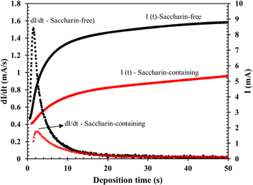
Figure 1. Comparison between the transient potentiostatic currents I(t) and change rate dI(t)/dt of saccharin-free and saccharin-containing electrolytes at a potential of −1.1 V versus Ag/AgCl.
Download figure:
Standard image High-resolution imageThe deposit growth mechanism of electrodeposition processes can be explored using experimental data on the current flow (i) during the deposition time (t). NiCoFe nucleation during the co-deposition process could be identified by comparing experimental transient currents with theoretical currents in the form (i/im)2 versus (t/tm) based on theoretical models proposed by Scharifker and Hills [30]. The instantaneous and progressive nucleation models have been given in equation (1) and (2), respectively.


Figure 2 shows the experimental plot of (i/im )2 versus (t/tm ) at a co-deposition potential of −1.10 V versus Ag/AgCl obtained from the two types of electrolytes compared with that of the theoretical values of the instantaneous and progressive models. Plots in figure 2(a) clearly indicated that the transient form of experimental current density followed the instantaneous nucleation type. Hence, the nucleation process of NiCoFe on ITO surfaces occurred at a high nucleation rate and led to the saturation of the nucleation site in a relatively short time. The high nucleation rate would have resulted in the formation of ultrafine crystallites as seen in the microstructure of FeCoNi deposits that shown in our previous report [4]. The current transient of saccharin-containing electrolyte at a co-deposition potential of −1.10 V was compared with that of theoretical models in figure 2(b). Plots indicated that the addition of saccharin to the electrolyte changed the transient characteristic and produced a gentler descent after the peak of (i/im )2. Such plots indicated that the presence of saccharin molecules in electrolytes modified the nuclei growth mechanism, meaning that the growth phase was slower than that in the saccharin-free electrolyte. This was also indicated by the low im and prolonged tm values compared to those obtained from deposition using the saccharin-free electrolyte as shown in the current transient (figure 1).
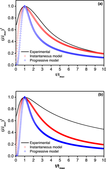
Figure 2. Comparison of the transient density between experimental and theoretical currents in NiCoFe co-deposition in saccharin-free (a) and saccharin-containing (b) electrolytes at an applied potential of −1.10 V.
Download figure:
Standard image High-resolution imageTo determine the effect of electrodeposition potential on the NiCoFe co-deposition process, transient currents as a function of time were recorded at different co-deposition potentials. The plot presented in figure 3 showed that the magnitude of the transient current im at a deposition potential decreased dramatically in the electrolyte containing saccharin compared to that in the electrolyte containing no saccharin. The decrease in transient current occurred at all deposition potentials.
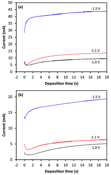
Figure 3. Representation of potentiostatic current-transients at different electrodeposition potentials in saccharin-free (a) and saccharin-containing (b) electrolytes.
Download figure:
Standard image High-resolution imageFigure 4 shows the maximum current flow in saccharin-free and saccharin-containing electrolytes at different electrodeposition potentials. Maximum current flows in the saccharin-free electrolyte increased from 15.3 mA at −1.00 V to 55.2 mA at a co-deposition potential of −2.00 V. In contrast, maximum current flows in the saccharin-containing electrolyte were relatively lower than that in the saccharin-free electrolyte at the same potential, which was 7.8 mA at a potential of −1.00 V, rising to about 41 mA at a potential of −2.00 V. The maximum current versus potential plot showed an ohmic relationship between the two types of electrolytes, which was like a current flowing through a conductor. The two electrolytes apparently differed in resistance values calculated using Ohm's law, and saccharin-containing electrolyte had a higher value. The low current flow in the system with the saccharin-containing electrolyte was due to its higher electrical resistance than the saccharin-free electrolyte, which indicated the adsorption of saccharin molecules on the electrode surface that inhibited electron transfer in the interface between the electrolyte and the electrode.

Figure 4. Maximum current flow during NiCoFe electrodeposition from saccharin-free and saccharin-containing electrolytes at different potentials.
Download figure:
Standard image High-resolution image3.2. Current efficiency, deposition rate and anomalous deposition of NiCoFe
The current efficiency (CE) value was determined from the ratio of the sample mass obtained (wj ) to the theoretical mass that should have been obtained when all currents are used in the metal deposition process (wt ) in the following equation [31].

Figure 5 shows the value of the CE of the thin NiCoFe layer at various co-deposition potentials during the synthesis process. CE represents the yield of mass obtained when all currents are used for the metal deposition process [18]. In the saccharin-free electrolyte, the CE value was 25.3% at −1.00 V and increased progressively at more negative co-deposition potentials, achieving a maximum CE of 88.2% at −1.75 V. Afterwards, CE dropped back to 68.6% at a potential of −2.00 V. The decrease in CE value at more negative potentials was due to an increase in the hydrogen evolution reaction (HER) [24, 28], which reduced the amount of metal ion reduction that occurred during deposition.
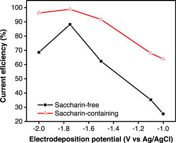
Figure 5. The efficiency of the NiCoFe co-deposition current in saccharin-free and saccharin-containing electrolytes at different co-deposition potentials.
Download figure:
Standard image High-resolution imageIn the saccharin-containing electrolyte, the change in CE value as an effect of the co-deposition potential showed a similar trend to that obtained in the saccharin-free electrolyte system. However, in the saccharin-containing electrolyte, the CE value was higher than that in the saccharin-free electrolyte at all applied potentials. Again, results indicated that saccharin was adsorbed by the electrode surface, which inhibited the rate of hydrogen evolution so that increased metal ions reduction during deposition.
The rate of NiCoFe deposition was calculated according to the deposited mass (mg) per minute per deposition area (cm2). The resulting values were compared between saccharin-free and saccharin-containing electrolytes at various deposition potentials (figure 6). The two curves indicated that the deposition rate increased as the applied potentials negatively increased and had the same maximum rate of 0.22 mg.cm−2.min−1. Such increases occurred due to the increase of current flow in electrolyte media when the co-deposition potential increased negatively. The presence of saccharin inhibited the HER in the system, which resulted in a relatively high deposition rate compared to that obtained during deposition without saccharin.
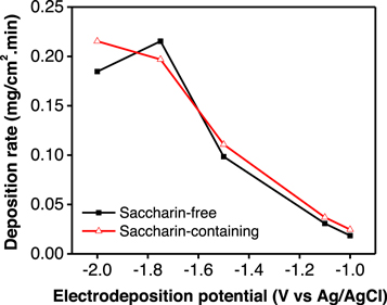
Figure 6. NiCoFe co-deposition rate in saccharin-free and saccharin-containing electrolytes at different deposition potentials.
Download figure:
Standard image High-resolution imageFurther analysis was performed to determine the composition ratio value (CRV) of each Fe, Co and Ni metal, which was calculated from the ratio between the mass fraction of metal in the deposit and the mass fraction of the metal in the electrolyte as defined in equation (4) [24, 32].

where M = Fe, Co and Ni.
The calculated CRV value of Fe, Co and Ni for saccharin-free and saccharin-containing electrolytes was plotted against co-deposition potentials in figure 7. The most obvious difference between the two was that the CRV for Fe deposited using the saccharin-free electrolyte between −2 V and −1.1 V was much higher than that using the saccharin-containing electrolyte. The CRV of Fe was between 7.1 and 9.5, while the content of Co and Ni in each deposit was 2.2–3.9 and 0.3–0.6 times the content of each metal in the electrolyte. These data suggested that the deposition of Fe2+ ions was more likely to occur in the electrolyte system used, while the deposition of Ni2+ ions was less preferable in the system. Ni is a more noble metal compared to Fe and Co, and such co-deposition characteristics are known as anomalous co-deposition [33], which occurs when a less noble metal is more easily deposited than a more noble metal.

Figure 7. Composition ratio values of NiCoFe co-deposition in saccharin-free and saccharin-containing electrolytes.
Download figure:
Standard image High-resolution imageIn the saccharin-containing electrolyte, the Fe content in the deposit was 11.2 at a co-deposition potential of −1.00 V. As potential negatively increased, CRV decreased significantly until it reached 3.3 at a potential of −1.50 V and continued to decrease to 2.3 at a potential of −1.75 V. The CRV of Fe metal in the saccharin-free electrolyte was lower than that obtained in the saccharin-free electrolyte due to the reduced HER as described in the above CE data. This condition decreased the concentration of hydroxyl ions, which play a role in the formation of Fe(OH)+ on the surface of the electrode. This provided an opportunity for other metal reaction, in this case, the deposition of Ni. For example, the CRV of Ni doubled from 0.39 at a potential of −1.00 V to 0.81 at a potential of −1.75 V. Based on these experimental data, it can be concluded that adding saccharin to electrolyte reduces observable anomalous deposition characteristics in the system.

Figure 8. Composition of Fe, Co and Ni in a thin layer synthesised from saccharin-free and saccharin-containing electrolytes measured using an atomic absorption spectroscopy method.
Download figure:
Standard image High-resolution image3.3. Composition and structure of NiCoFe films
The chemical composition of NiCoFe films has been plotted in figure 8. Plots compared the composition of deposits obtained from saccharin-free and saccharin-containing electrolytes. In general, the plots clearly indicated that the alloy composition of NiCoFe deposit was sensitive to co-deposition potential. However, the change of the alloy compositions from the two electrolytes system showed a similar trend when the potentials varied. This result was in accordance with previous studies [34, 35], which showed that the composition of deposits prepared using electrodeposition was strongly influenced by the potential that applied to the electrochemical system.
In the present study, the average percentage of Fe and Co atoms was higher at a more negative co-deposition potential in samples obtained from saccharin-free electrolyte compared to deposits from saccharin-containing electrolyte. Their composition changed at different co-deposition potentials. In this case, at a co-deposition potential of −1.00 V, the composition of Fe and Co was 22.64 at.% and 48.30 at.%, respectively. At a more negative co-deposition potential, the composition of the two metals continued to decrease to 17.10 at.% (Fe) and 27.96 at.% (Co) at −2.00 V. Conversely, Ni composition increased from 29.05 at.% at −1.00 V to 54.94 at.% at −2.00 V. Ni had a more standard negative reduction potential compared to Fe and Co. Hence, at a more negative co-deposition potential, Ni content increased. The addition of saccharin to electrolyte changed the composition of deposits. NiCoFe deposits at co-deposition potentials between −1.10 V and −2.00 V in saccharin-containing electrolyte had a lower Fe and Co content than those in saccharin-free electrolyte. The Ni content of deposits in saccharin-containing electrolyte was higher than that in saccharin-free electrolyte due to saccharin's role in reducing the anomalous co-deposition characteristics discussed above.
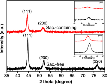
To evaluate the deposits further, NiCoFe films were examined under an XRD. Figure 9 compares the diffraction pattern of NiCoFe films electrodeposited from saccharin-free and saccharin-containing electrolytes with peaks broadening due to the fine crystal of the alloys. The observed peaks at 2θ 44.65°, 51.88°, and 76.49° that could be assigned to (111), (200) and (220) diffraction planes, respectively, confirmed the formation of single phase NiCoFe [4, 6, 10]. The XRD patterns only varied in the position of peaks due to a slight shifting, which is associated with the different compositions of NiCoFe alloys. In addition, the (220) peak of NiCoFe alloy obtained from the co-deposition Fe, Co and Ni was absent in the XRD for saccharin-containing electrolyte. This might be due to the minor preferential crystallite orientation of deposits in the form of a thin layer above the substrate. The mean crystallite size detemined using the Scherrer equation by substracting instrumental line broadening showed finer grains of 11.00 nm obtained from the film electrodeposited from saccharin-containing electrolyte compared to 17.58 nm from those prepared without the additive. The small crystallite size confirmed the high nucleation rate during NiCoFe deposition at which the growth phase was decelerated by the presence of additive.
Figure 9. X-ray diffraction patterns of thin NiCoFe films synthesised from saccharin-free and saccharin-containing electrolytes. Inset: the shifting of (111) and (200) peaks.
Download figure:
Standard image High-resolution image
4. Conclusion
The electrodeposition of CoNiFe film on ITO-coated flexible PET was carried out in saccharin-free and saccharin-containing electrolytes. The electrodeposited films were in the crystalline phase of CoNiFe, and their chemical composition changed when the applied co-deposition potentials varied. The presence of saccharin modified the kinetic growth of CoNiFe deposits and significantly increased deposition CE, slightly enhanced the deposition rate and diminished observable anomalous co-deposition characteristics. Nuclei growth was slower, and this was indicated by the change of (i/im )2 versus (t/tm ) plot as well as a low im and prolonged tm , which can be attributed to the adsorption of saccharin molecules on the electrode surface. This condition kinetically inhibits mass transport as confirmed by the high resistance of saccharin-containing electrolyte. The adsorbed saccharin also played a role in impeding the HER, which increased the electrodeposition CE at all applied potentials. The decrease in hydrogen evolution diminished observable anomalous co-deposition characteristics, especially at relatively high deposition potentials, due to a decrease in the formation of metal hydroxide ions, which increased Ni deposition as indicated by the increase in the CRV of Ni.
Acknowledgments
The authors gratefully acknowledge the financial support provided by Universitas Negeri Jakarta, Universitas Indonesia and Kementrian Pendidikan dan Kebudayaan, Riset dan Teknologi Republic of Indonesia under PTUPT grant with contract number 2/E4.1/DSD/LPPM/2021.
Data availability statement
The data that support the findings of this study are available upon reasonable request from the authors.