

Abstract
We performed time-domain propagating spin-wave spectroscopy for forward spin waves in a ferromagnetic metallic waveguide in the presence of electric current. The forward spin waves exhibit a large propagation delay and a 35% amplitude change with a smaller current injection of 6 × 10¹⁰ A/m2, showing a 2 times larger modulation than backward volume spin waves. By measuring electric-current effects in 4 distinct experimental configurations, we found that a current-induced Doppler shift coincided with an Oersted field frequency shift under our experimental conditions. By separating the two phenomena, we evaluated each contribution on the propagating forward spin-wave packet.
Export citation and abstract BibTeX RIS
1. Introduction
Nanomagnonics, which is the research field to manipulate spin waves (SWs) in nanoscale devices, has attracted of great interest as an information processing technology, since it shows a potential to overcome the serious limitation of conventional electric-current-based devices.1–13) SWs can be used as information carriers having carrier frequencies from gigahertz (GHz) to terahertz (THz) and are expected to cause no electric Joule heating. A spin wave allows a peculiar information encoding into its phase and provides a multiple input/output logic in devices. Furthermore, SWs can be manipulated via thermal and optical phenomena. For example, the thermal gradient of a device becomes an energy source of spin-wave carriers and is now considered to be the key technology for energy harvesting. The upcoming magnon transistor, a nanomagnonic function, will be a highly integrated architecture combining thermal, optical, and electrical systems.
To develop the spin-wave logic architecture, the forward volume spin wave (FVSW) with out-of-plane magnetization shows isotropic propagation in the device plane, and the FVSW will make a logic architecture simple than the backward volume (BV) and Damon-Eshbach (DE) SWs with in-plane magnetization. As proved by a recent work,12) a magnonic majority gate was realized using FVSW in yttrium iron garnet (YIG), and the NAND, NOR, AND, and OR logic operations were performed by a single ψ-shaped element. To develop an integrated ψ architecture, we have to establish a local manipulation method for FVSW in metallic systems.14–21) Since metallic systems have an electronic system, we can directly control SW excitation and SW modulation via the spin-transfer torque (STT)22–25) and spin-Hall26–29) effects.
The interaction between electric current and SW can be described by the full Landau–Lifshitz–Gilbert–Slonczewski equation:30,31)

where α is the magnetic damping, β is the magnitude of nonadiabatic STT, γ is the gyromagnetic ratio, u0 (= −μBjP/eMs) is the magnitude of adiabatic STT, P is the spin polarization, μB is the Bohr magneton, j is the current density, e is the electron charge, and Ms is the saturation magnetization. To understand magnetization dynamics, i.e., SW induced by an electric-current, we have to carry out a time-domain propagating spectroscopy of FVSWs since it provides us important information about SW waveforms under electric current. A detailed understanding of electric-current effects on FVSW packets, such as the phase and amplitude modulations of waveform and excitation delay, is essential.
In this paper, we report on the time-domain propagating SW spectroscopy of FVSWs in a metallic waveguide. The FVSW packet was elongated to 4–8 ns owing to its lower group velocity than the DE spin-wave velocity. Electric-current injection resulted in large frequency and amplitude changes for FVSW packets. Interestingly, the amplitude of FVSW packets was modulated by ±35% of the initial SW, showing a much larger modification than DE and BV SWs. By analyzing a systematic data set of FVSW packets, both an Oersted-field induced frequency shift and a current-induced Doppler shift were evaluated experimentally.
2. Experimental methods
Figure 1 shows a schematic illustration of the experimental setup used in the time-domain propagating SW spectroscopy.6,23) The SW waveguide was made of a permalloy film (Fe19Ni81/SiO2; thickness, 35 nm/35 nm). To both edges of the waveguide, a pair of metal electrodes were attached as a source and a drain of spin-polarized current, which induced the current-modulation effect on SWs. To minimize Joule heating in the device, we used a pulse current of 10 ns duration.
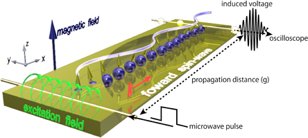
Fig. 1. Schematic of time-domain propagating spin-wave spectroscopy. A fast microwave pulse was injected into the excitation antenna, which generates an excitation field of spin waves. At the detection antenna, a propagating spin wave generates an induced voltage, which signals an oscilloscope.
Download figure:
Standard image High-resolution imageExternal magnetic fields magnetize the waveguide in the z-axis direction so that SWs can propagate as FVSWs.11,12,22) SWs were excited and detected with a pair of asymmetric coplanar strip (ACPS) transmission lines over the waveguide.18) For the time-resolved measurement of current-induced SW dynamics, we injected voltage pulses into one ACPS with a 65 ps rise time at 100 kHz repetition frequency, generating a microwave magnetic field for generating a SW. The SW propagates in both directions normal to the ACPS and induces an additional magnetic flux on the other ACPS connected to a 20 GHz sampling oscilloscope. The present study was performed by measuring a set of devices that have different propagating distances (g) of 5, 10, and 40 µm between the ACPSs.
3. Results and discussion
3.1. FVSW packet and SW properties
Figure 2(a) shows a typical waveform of a FVSW packet at μ0Hext = 1.16 T. At the propagation distance g = 5 µm, the SW packet emerged at tcenter = 3.8 ns as indicated by the arrow, and SW showed the amplitude A = 110 µV. The FVSW packet exhibits a clear oscillation from 1.1 to 7 ns (Δt = 6 ns). Compared with the DE spin-wave packets with Δt = 2 ns,6) the SW packet shows an elongated shape. In the case of g = 10 µm, a FVSW locates at tcenter = 6.9 ns and diminishes its amplitude to A = 45 µV. In the case of g = 40 µm, the SW was too attenuated (A = 5 µV) to detect its packet shape (not shown).
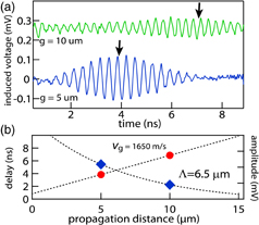
Fig. 2. (a) Waveforms of FVSW at different propagation distances g = 5 and 10 µm. A magnetic field μ0Hext = 1.16 T is applied normal to the film plane. Propagation distance dependences of SW amplitude and arrival time. The arrival time exhibited a linear dependence on g, as shown by the solid circles in red, whereas the amplitude showed an exponential decay as shown by the solid diamonds in blue. The dashed lines represent the fitting curves.
Download figure:
Standard image High-resolution imageTo understand the basic property of FVSW, the propagation distance dependences of A and tcenter are plotted in Fig. 2(b). The amplitude A shows an exponential decay.6) Using the formula A0 exp(−g/Λ), the SW attenuation length Λ is estimated to be 6.5 µm which is the same those obtained in previous works. As shown by the linear dependence of tcenter, the group velocity of SW is determined to be vg = 1650 m/s, which is much smaller than those of BV32,33) and DE6,23) spin waves.
3.2. Resonance frequency and FVSW dispersion relation
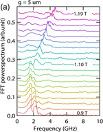
To confirm that the SW packets reflect the FVSW property, we measured the magnetic field dependence of resonant frequency. By analyzing the fast Fourier transform (FFT) of waveforms, the resonant frequency is deduced and shown in Fig. 3. As shown in Fig. 3(a), in stronger magnetic fields 1.1 < μ0Hext < 1.2 T, the peaks exhibit a clear frequency shift in response to the variation in magnetic field. The frequencies of the peaks are plotted in Fig. 3(b) and categorized by colors. As shown in solid circles in blue, the magnetic-field-dependent frequencies are fitted by the FVSW dispersion relation
where Ms is the saturation magnetization, Heff (= Hext − Ms) is the effective field, γ is the gyromagnetic ratio, k is the wavenumber, and d is the film thickness. The fitting parameters were Ms = 1.03 T, γ/2π = 28 GHz/T, and k = 0.4 rad/µm, which were in agreement with the previously reported values. The wavenumber is determined using our ACPS geometry. Simultaneously, the group velocity vg = ∂ω/∂k was calculated and is shown in the inset of Fig. 3(b). The expected group velocity is vg = 1526 m/s at μ0Hext = 1.16 T, which is the same as the experimental value within an 8% error. From this analysis, we confirmed the existence of propagating FVSWs in the field range of μ0Hext > 1.1 T.
Download figure:
Standard image High-resolution image
Fig. 3. (a) Magnetic field dependence of resonance frequency deduced by FFT of the SW waveforms. (b) Analytical calculation of FVSW dispersion relation and group velocity (inset). The solid circles in blue, green, and red correspond to the resonances of FV, DE, and BV SWs, respectively.
Download figure:
Standard image High-resolution imageIn weaker magnetic fields 0.9 < μ0Hext < 1.1 T, we can observe a double-peak structure having centers at f = 1.69 and 2.30 GHz. With increasing magnetic field from 0.9 T, the peaks at f = 1.69 GHz shift very slightly toward 1.63 GHz (Δf = −60 MHz) without a change in its magnitude. On the other hand, the peak position at f = 2.30 GHz shifts toward 1.94 GHz (Δf = −360 MHz) with decreasing peak magnitude. Two peaks appear to be a single peak at 1.05 T and may vanish at approximately 1.06 T. In weaker magnetic fields of 0.9 < μ0Hext < 1.05 T, the magnetization of the waveguide does not perfectly saturate toward the perpendicular direction (this is consistent with the parameter Ms = 1.03 T), and thus a simple picture of FVSW, DESW, and BVSW is not valid. Since the SW resonance under the unsaturated condition is not within the scope of this paper, we do not discuss its details but only comment as follows: owing to the in-plane components of magnetization, the peak at f = 1.69 GHz may originate from the BVSW nature and the peak at f = 2.30 GHz may originate from the DESW nature. For example, if we use a rough assumption of in-plane magnetization with a very small internal field of 3.2 mT, we can deduce the resonant frequencies fDE = 2.8 GHz and fBV = 1.6 GHz from the SW dispersion relations. This is not a rigorous picture owing to the tilting magnetization; however, both the resonance frequency and its tendency to depend on the magnetic field are well explained.
3.3. Current-induced modulation of FVSW
To investigate the electric-current effects on the propagating FVSWs, we examined the electric-current injection into the SW waveguide at μ0Hext = 1.16 T. The propagation distance is fixed at g = 5 µm. As proved in previous works,6,23) the antenna excitation method causes an asymmetric excitation field distribution around the antenna, involving a SW nonreciprocity. The spin-wave packet can be excited by four different excitation configurations using two antennas:  ,
,  ,
,  , and
, and  . Here, −M is set by applying the external magnetic field Hz along the −z-direction. The reversed SW wavevector −k is realized by switching the roles of excitation and detection antennas.
Figure 4 shows the electric-current modulation of SW packets in each configuration. The amplitude A and the center position tcenter of the SW packets were deduced by fitting using the Gaussian-shaped packet. As mentioned above, the initial amplitude A(0) differs for each configuration owing to the excitation nonreciprocity: 117 µV for  , 68 µV for
  , 89 µV for
  , and 56 µV for
  .
.
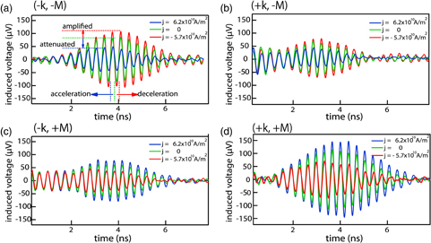
Fig. 4. Time-domain FVSW waveforms under electric currents. The propagation distance is g = 5 µm. (a) Rightward moving wavevector k and (b) leftward moving wavevector −k in application of magnetic field to the −z-direction. (c) Leftward moving wavevector −k (−x-direction) and (d) rightward moving wavevector k (x-direction) in application of magnetic field in the z-direction.
Download figure:
Standard image High-resolution imageAs shown in Fig. 4(a), in the  configuration, a positive current j = +6.2 × 10¹⁰ A/m2 attenuated the SW amplitude by 32 µV but accelerated by −380 ps, while the negative current j = −5.7 × 10¹⁰ A/m2 amplified the SW amplitude by 32 µV and decelerated by +140 ps. In the case that the direction of the SW wavevector was inverted to be
  as shown in Fig. 4(b), the positive current j = +6.2 × 10¹⁰ A/m2 attenuated the SW amplitude by 19 µV but accelerated by −310 ps, while the negative current j = −5.7 × 10¹⁰ A/m2 amplified the SW amplitude by 7.7 µV and decelerated by +176 ps. In the case that the direction of magnetization was changed to M, the roles of positive and negative currents were inverted; the positive sense of current decelerated the SW packet, whereas the negative sense of current accelerated the SW packet [see
  shown in Fig. 4(c) and
  in Fig. 4(d)]. The electric current effect strongly depends on k and M.
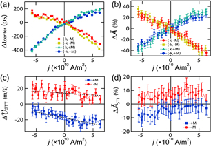
In Fig. 5(a), the detailed current dependences of tcenter(j) for all configurations are shown. The time difference Δtcenter = tcenter(j) − tcenter(0) was measured from the SW packet without current. Clearly, Δtcenter shows a nonlinear dependence on j for each configuration. For the fixed magnetization direction, for instance,  and
and  , note that the total values of Δtcenter are almost the same but slightly different. This point is recognized for the other configurations between
  and
and  . A weak spin-transfer torque effect can be superimposed on a nonlinear background signal, which will be the Oersted field effect induced by electric current. This effect was pointed out and discussed in several papers.23,25,33) In contrast, the SW amplitude shown in Fig. 5(b) shows a linear dependence on j. Here, note that we used a normalized SW amplitude given by
  owing to the nonreciprocity. As in Δtcenter, we can detect small differences in the
  slopes, if we compare the pair of
  and
and  and the pair of
  and
and  .
.
Fig. 5. Electric-current dependences of (a) the center position of SW packet measured from the waveform without current and (b) the amplitude of SW packet. (c) Changes in group velocity due to spin transfer torque. The dashed lines are linear fitting lines. (d) Change in amplitude due to spin transfer torque. The data offsets were used to improve the visualization.
Download figure:
Standard image High-resolution image
To analyze the STT effect, we have deduced the changes in group velocity and amplitude using the following subtraction procedures:


For a fixed j-direction, only the intrinsic effect of STT changes its sense with respect to the inversion of the wavevector k, whereas the effects of the Oersted field and Joule heating, among others do not. According to Eq. (1), we can deduce the following equations as in a previous paper:23)


where u0 (= −μBjP/eMs) is the magnitude of adiabatic STT, and g is the propagation distance.
From the slope in Fig. 5(c), we can estimate the spin polarization P of electric current. In the case of the −M configuration, we have P = 0.67, which is in agreement with the reported value for DESW. The spin transfer torque on FVSW was successfully detected by this time-domain measurement; however, we should be careful about the evaluation of its magnitude. If P is evaluated from the slope of the M configuration, the spin polarization becomes P = 2.1 resulting in a nonphysical interpretation. This is caused by a small signal-to-noise (S/N) ratio in the raw data. Compared with the DESW amplitude, the SW amplitude itself was smaller than 1/20 of the DESW amplitude and easily affected by the current-induced Oersted field. The effect of the small S/N ratio was not perfectly eliminated. If we carefully check the data of M and analyze it only in the positive current region j > 0, we can find a reasonable value of P = 0.56. However, we cannot proceed with an accurate discussion about the magnitude of P. For further P evaluation from FVSW, we need a propagation distance smaller than 5 µm to obtain a much better S/N ratio. At the present stage, it is only possible to state that the spin transfer torque has an approximately 8% contribution to the total current-induced modulation.
Concerning the evaluation of the nonadiabatic torque β from the slope shown in Fig. 5(d), we were unable to detect a physically reasonable β owing to the small S/N ratio. The  values are almost unchanged and remained at the noise level. As shown in Fig. 5(d), ΔASTT caused by both the Oersted field and spin transfer torque effects reaches 35% and is much higher than those of BV and DE spin waves.23,33) This means that the effect of the Oersted field is much greater than that of the spin transfer torque, which affects the evaluation of
  . The effect of the current-induced Oersted field on the waveform and why the FVSW is strongly affected by Oersted field compared with the other SW modes will be the next subjects of our investigation.
4. Conclusions
The effect of current injection onto forward volume spin waves was experimentally investigated. We observed a large acceleration of spin wave packets of up to 400 ps and an amplitude change of up to 35% with a current density of 6.2 × 10¹⁰ A/m2. These large changes are mainly caused by the current-induced Oersted field. By using a subtraction procedure, we can detect the spin transfer torque effect on propagating FVSWs. Since the evaluation of spin polarization has a large error, the present time-domain method for FVSWs should be revised. From an application viewpoint, the control of spin-wave amplitude is the key issue for magnonic logic operation. The total amount of amplification (35%) is much larger than those obtained on the basis of other amplification principles, such as spin-transfer torque and spin-Hall effect; thus, the forward volume spin-wave in a metallic waveguide showed a potential for spin-wave-based devices.
Acknowledgement
K.S. acknowledges the Grants-in-Aid for Scientific Research (16K13670 and 16H02098) from the Japan Society for the Promotion of Science (JSPS).
Biographies

Koji Sekiguchi received his B.E., M.E., and D.E. degrees from Keio University, Yokohama, Japan, in 2002, 2004, and 2007, respectively. He is currently an Associate Professor of the Faculty of Engineering, Yokohama National University. His general research interests include the control of magnon current in nanoscale devices to build a block of magnon transistors. He received the Young Scientists' Prize, the Commendation for Science and Technology from the Minister of Education, Culture, Sports, Science and Technology in 2015.

Daichi Chiba received his B.E., M.E., and D.E. degrees in Electronic Engineering from Tohoku University, Sendai, Japan, in 2000, 2001, and 2004, respectively. He is currently an Associate Professor of the Department of Applied Physics, The University of Tokyo. His general research interests include the control of magnetic properties of materials using electric fields, electric currents, or mechanical stress applications. He received the Sir Martin Wood Prize from the Millennium Science Forum in 2012, the Incentive Award of Marubun Research Promotion Foundation in 2015, and the JSPS Prize from the Japan Society for the Promotion of Science in 2017.

Takehiro Tachizaki received his B.E., M.E., and D.E. degrees from Hokkaido University, Sapporo, Japan, in 2002, 2004, and 2007, respectively. He worked at Hitachi, Ltd. from 2007 to 2012 and was engaged in the research and development of industrial measurement technology. His research interests include high-resolution and high-precision measurement of material surfaces by scanning probe microscopy, optical interferometry, and time-resolved spectroscopy. He likes designing and conducting measurements using his own designed equipment. He won the R&D100 Awards twice in 2011 and 2014.